Output Devices
Group Project
This week's group assignment was to measure the power consumption of an output device. My group chose to measure the power consumption of a motor. We hooked the motor up to a power supply and measured the power using an oscilloscope. Then we looked at the relationship between voltage, current, and the motor function/speed. Voltage and current change proportionally, and as they increase, the motor speed increases as well. We also learned about Pulse Width Modulation. PWM is esssentially a method of creating a 'medium' using a microcontroller that only has high or low functions. This is achieved by alternating between high and low quickly enough that nothing is visable to the human eye. We tested out different speeds of this with an LED, and noted the correlational relationship between speed and brightness.
Individual Project
For this week's group project, I had to connect and program an output device on a board I designed. Two weeks ago, for Input Devices Week, I designed and fabricated a board that connected to a Temperature and Humidity Sensor via a three-pin connector. The process for designing, milling, and soldering that board can be found under the Input Week tab. Luckily, the connections on that board were the same as I would have needed to make this week, so I was able to reuse the board.
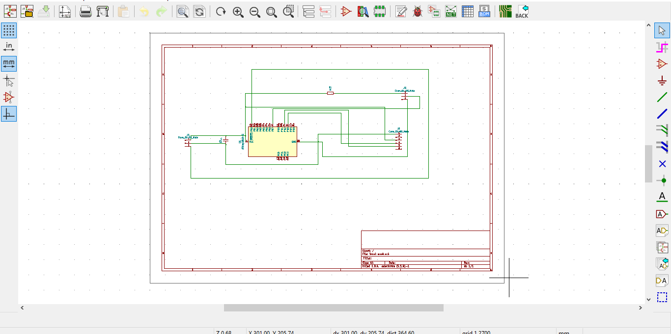
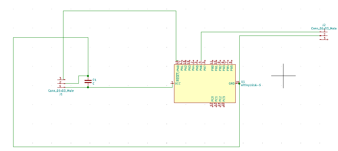
Here is the Kicad Schema
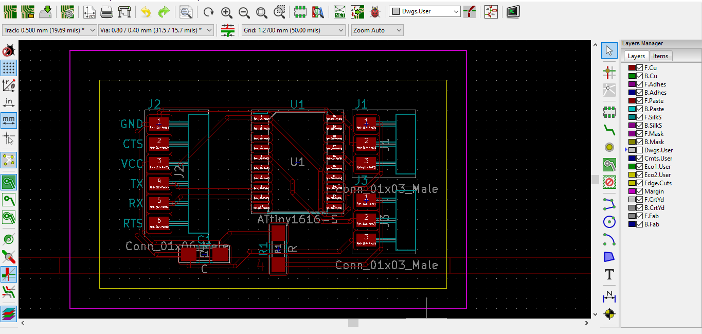
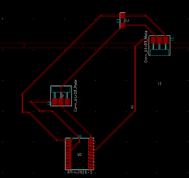
And here is the PCB board layout
During Input Week, right after I had gotten my board to work a couple of times, it suddenly stopped working. I had attributed it to the fact that there had been a bad connection I had remedied with copper wire and some solder, and figured that the wire had moves a little and was no longer connected.
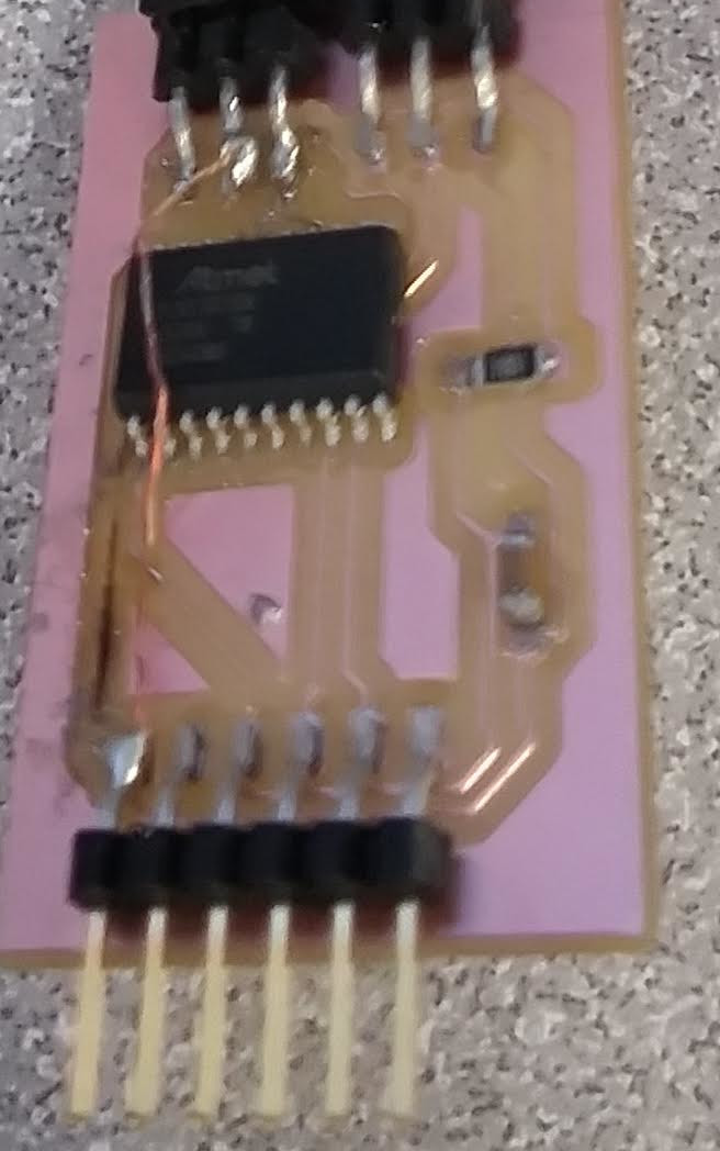
In the bottom left of the board pictured below, there is a spot where the copper seems to disappear. This is because the copper did in fact disappear, right after I foolishly removed a solder ball with tweezers much too agressively.
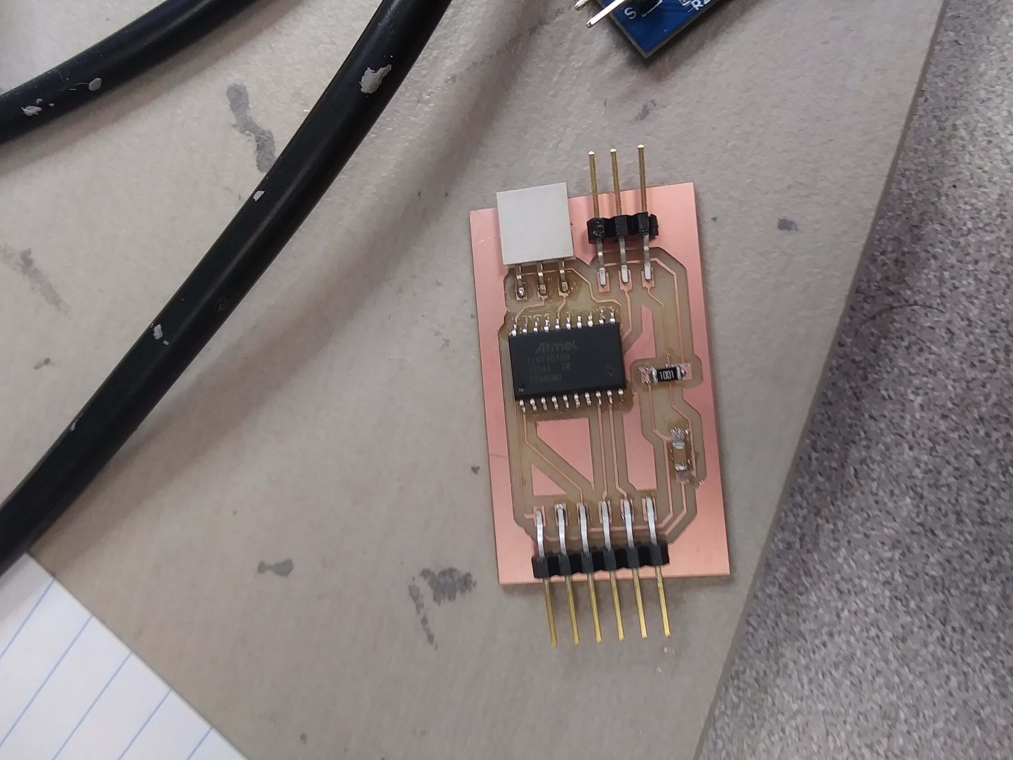
Because this connection was no longer intact, I needed to reconnect the two. The quickest solution to this was using more solder and copper wire, this time directly on the pins it was connecting.
It isn't the most aesthetically pleasing board and also, as I learned after, is a slight electrocution hazard, but it connected the two pins quite well.
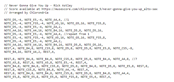
My output device for this week was a speaker. Online, there is an impressively large repository entitled Arduino Songs. I cloned that repository and selected the code for Never Gonna Give You Up by Rick Astley.
Arduino speakers don't have fantastic audio quality, so their is essentially an almost (but not quite) melodic series of beeps. The songs do resemble the originals relatively well, all things considered.
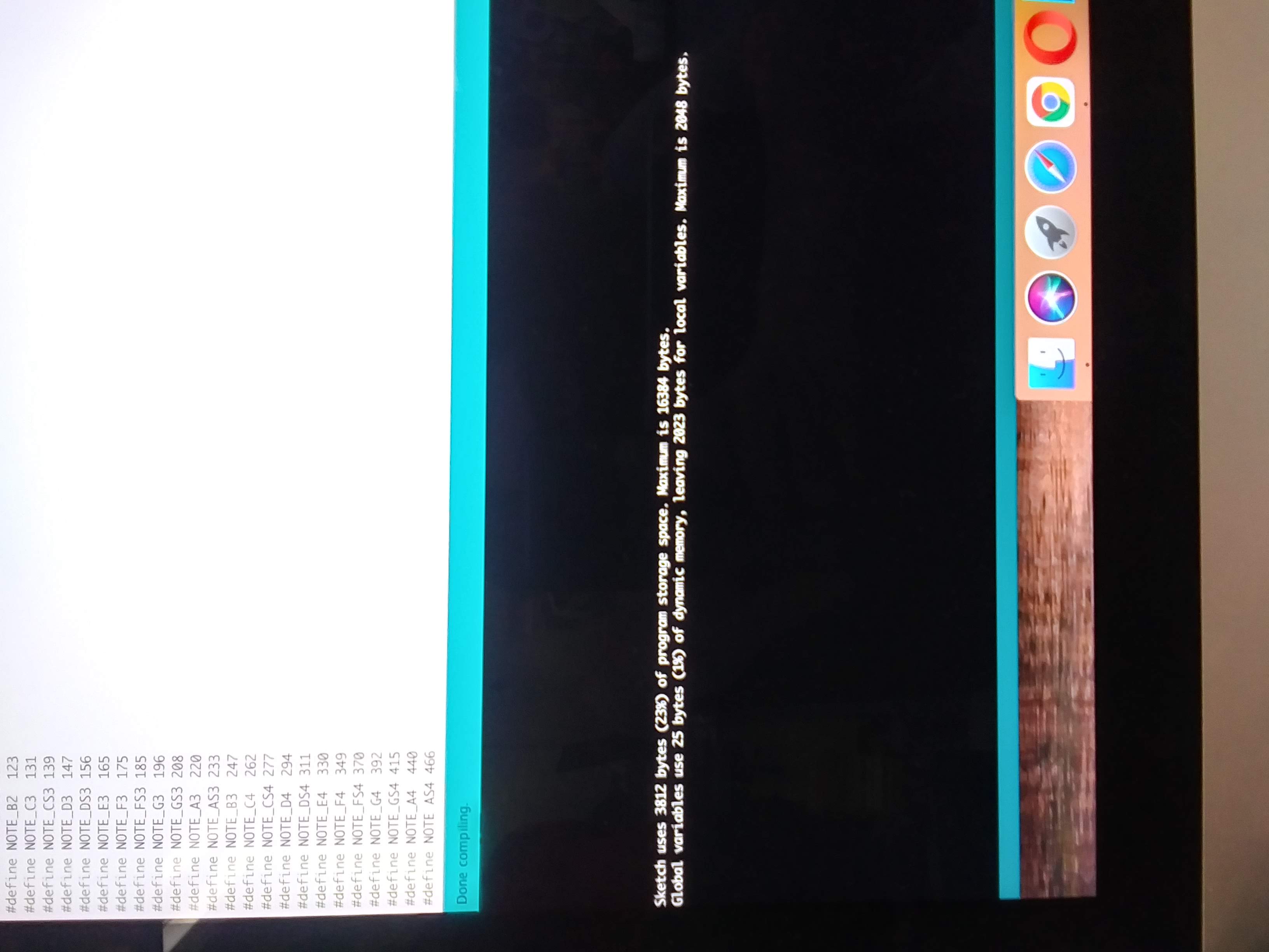
I put that code into Arduino and compiled it.
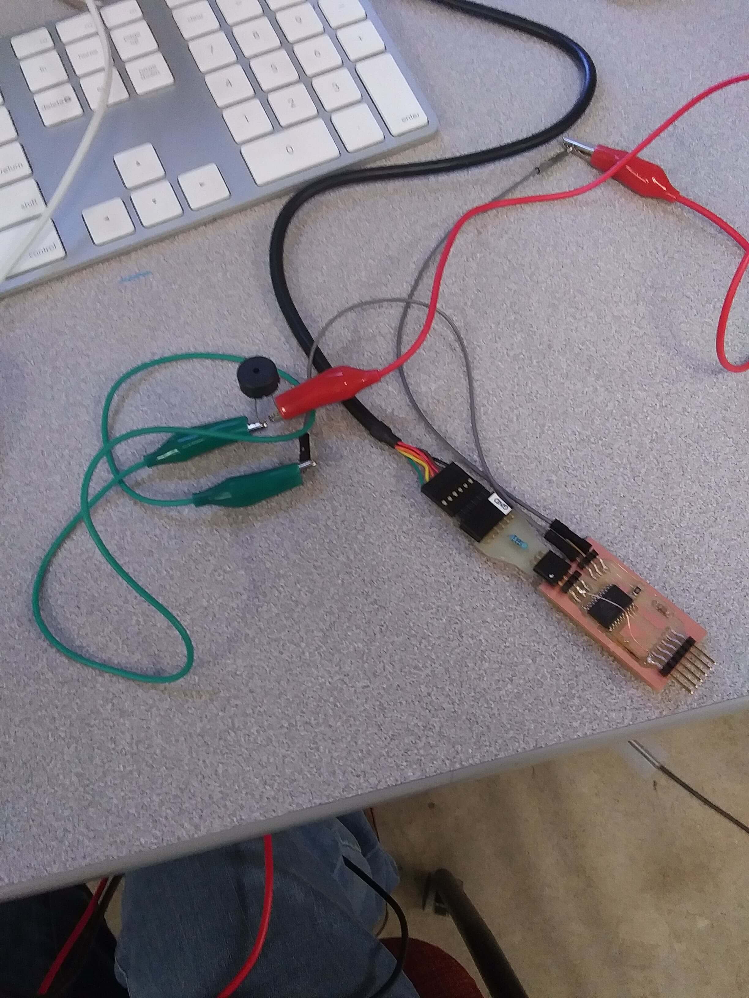
After that, I hooked the speaker up to the board.
Then I uploaded the code. This did not work, due to an UPDI initialization failure.

I used the multimeter to run continuity tests throughout the whole board. I discovered a small ball of solder that was connecting two tracks. Using tweezers, I removed the solder and checked the continuity again. This time the two were not connected. I reuploaded the error again, but got the same error. Because my connections and continuities were all correct, I figured that my issue might lie within the AtTiny, which had experienced a lot of heat with all of my soldering. I replaced the microcontroller, ensured the soldering process did not mess up any pathways, then attempted to unload the code once again. Once again, there was another UPDI failure. I'm not entirely sure what the issue may be. Everything that needs to be connected is connected and, conversely, there are no unnecessary connections. The microcontrolleer is new and should be working, and I tested out a second FTDI cable to ensure that that was not malfunctioning. Additionally, I used a breadboard to double check the code and speakers all worked.
After consulting others in the lab, I decided to design and mill a second board. This board has two connectors, a capacitor, and a microcontroller.
Then I milled it and soldered all of the components on.

I decided to program it to play Hedwig's Theme song from Harry Potter, which I accessed from the same place the Rick Astley Song is from. I have linked them both below.
Here's a video of the working board with it's speaker:
VideoLinks
Arduino SongsMy Code
New Board Kicad Schema
Board PCB