Computer Controlled Cutting
This week’s assignment on Computer Controlled Cutting had three parts: a group assignment working with the laser cutter, vinyl cutting, and creating a parametric construction kit.
Group Assignment
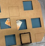
The group assignment for this week was to characterize our laser cutter’s kerf, speed, power, focus, and joint clearance. Kerf is the amount of material that is burned away by the laser while a material is being cut.
Our group used Adobe Illustrator to create 50x50mm squares on 0.15mm thick cardboard.
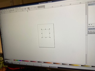
We ran 8 trials, each run changing either the speed or the power of the laser.
Then, we created an excel spreadsheet to record the speed and power, and to calculate kerf.
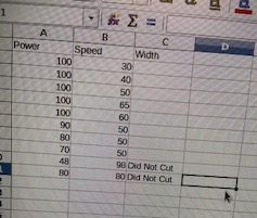
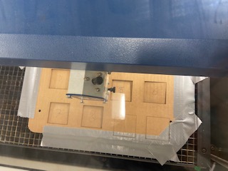
After laser cutting was finished, we measured each square using a calibrator. The size of each square was subtracted from 50.0mm, the size of the original square. This gave us the kerf of each individual square. We then created an R program to make a linear model, to try and see if speed and power are correlated with kerf.
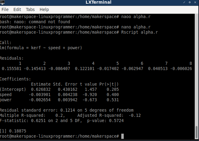
No correlation was found. Then, we decided to mess up the focus of the laser and make a square. The laser burned the exterior of the square pretty significantly. The kerf was significantly larger than the other trials, implying that the kerf is correlated with the laser’s focus, rather than speed and power.
Vinyl Cutting
This week, we were also challenged to cut something on the vinyl cutter. My Fab Lab has several groups that work together, so for this assignment, my group decided to design a logo using Affinity Designer, which is a vector graphics editor.

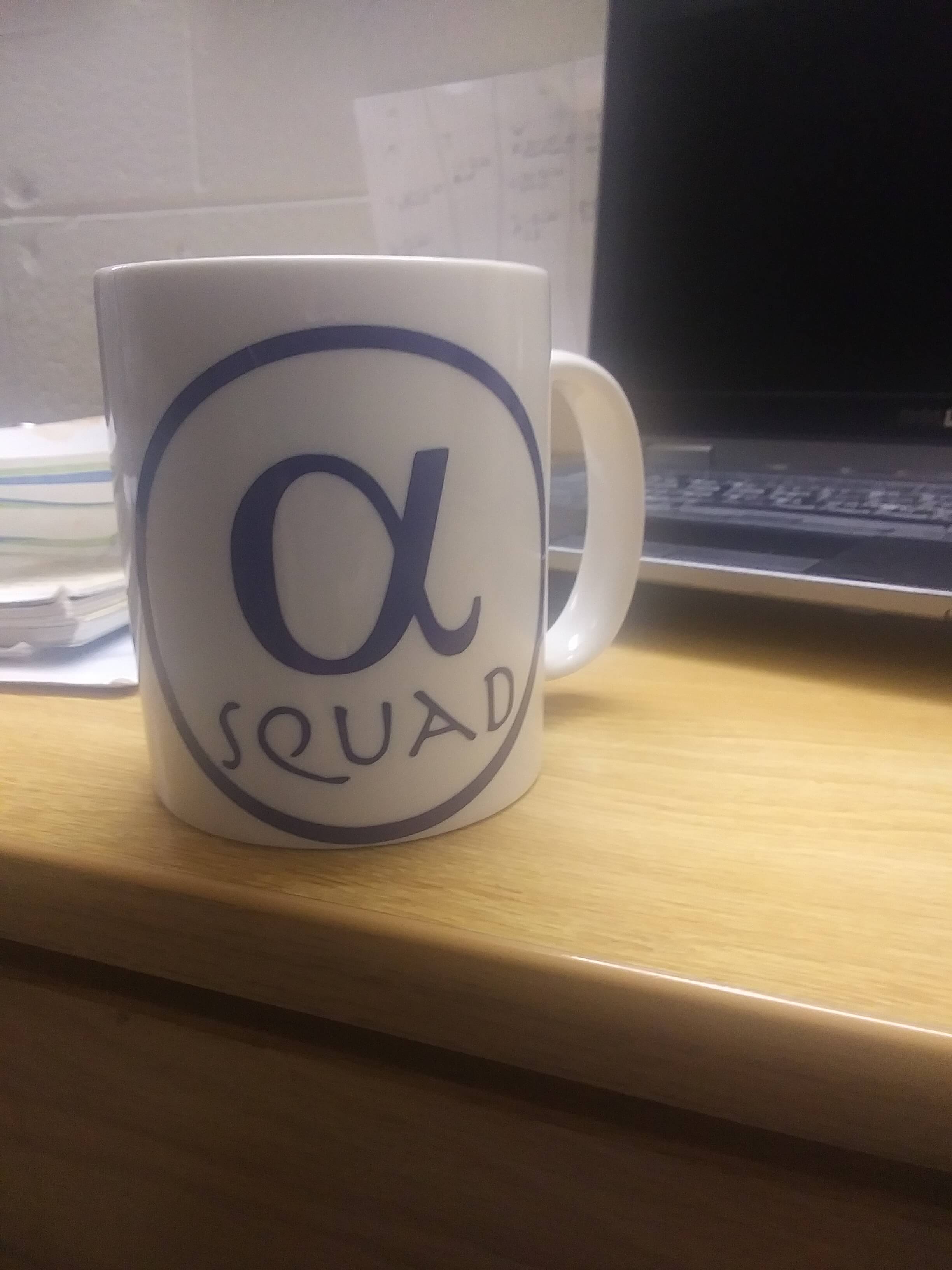
Our logo contained both text and graphics. We included a graphical rendition of an alpha with the word "squad" under it. Then that was enclosed in a circle.

We wanted multiple copies of the logo to vinyl cut, so we duplicated the logo in different sizes until we had as many as we.

We exported the design to Sure Cuts A Lot, a software that helps design and cut.

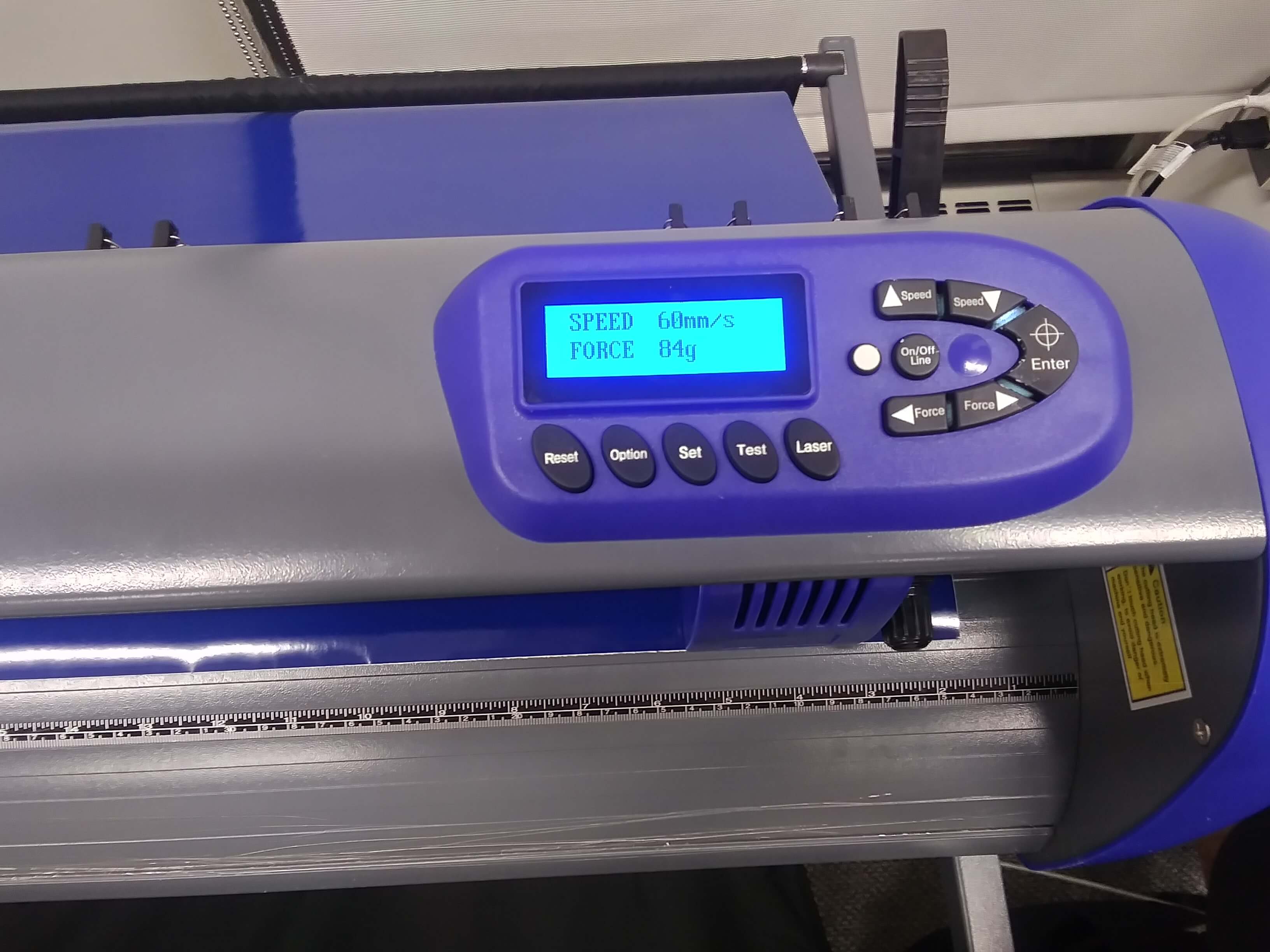
Then we set the speed to 60mm/s and the force to 84g and began cutting. This was a slower process than anticipated, likely because we were cutting so many copies of our logo.
Once the logos finished cutting, I cut out a rectangle around the logo I wanted to use, and began the weeding process. Weeding was a bit difficult, because some of the letters in the logo were very small and began to peel off.

After I finished removing all the excess material, I applied transfer tape to remove it from the sheet.

I had a blank mug that I wanted to put the logo on, so I set the logo onto the center of the mug and used a plastic card to get rid of the bubbles.

The logo did come out a bit uncentered, and one or two spots of the logo’s exterior circle wrinkled a bit, but overall the process went pretty smoothly, and my skills will improve with practice.
Parametric Construction Kit
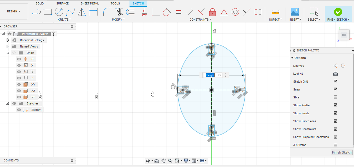
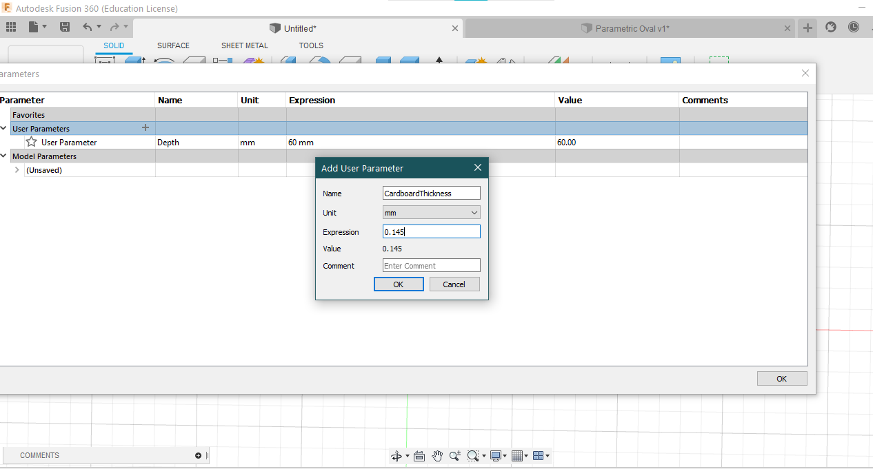
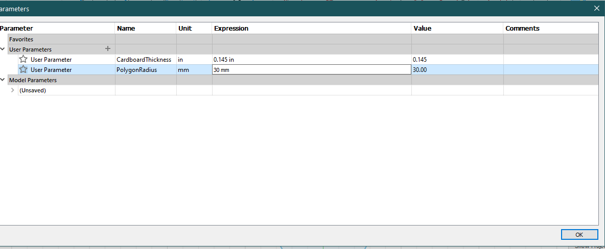
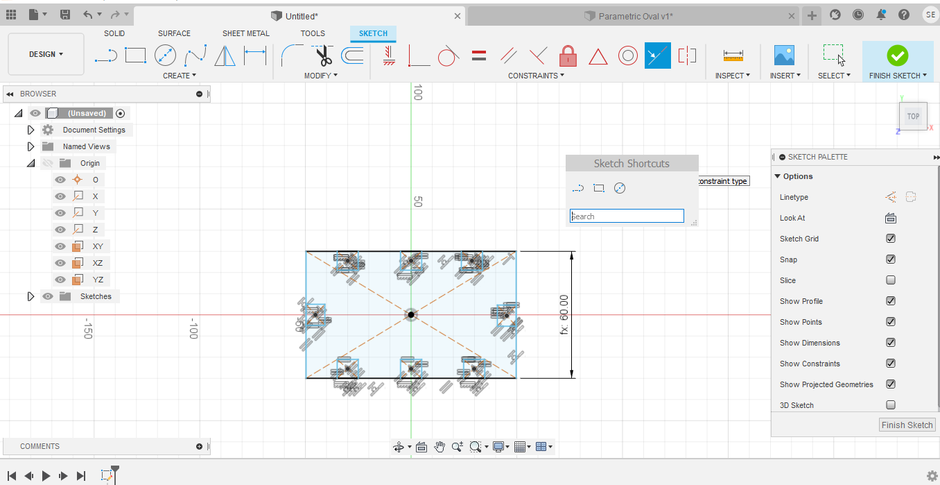
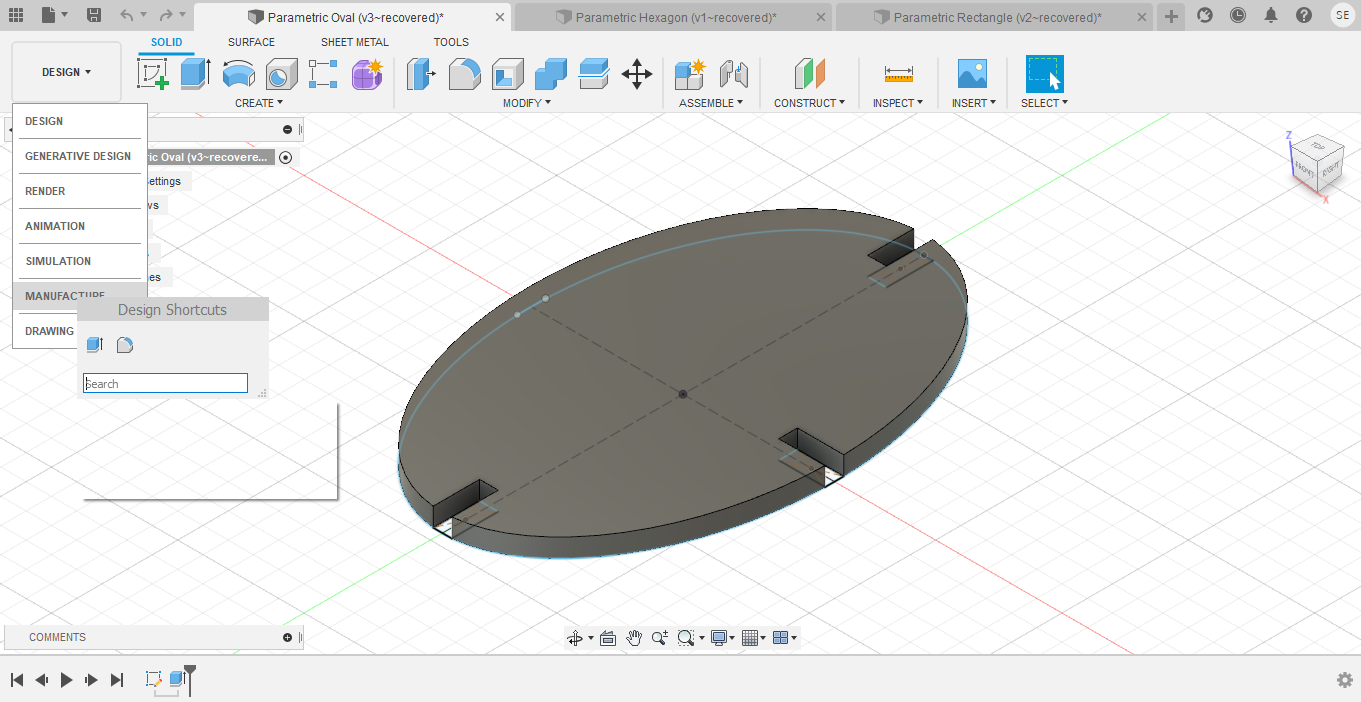
For my construction kit, I decided to make three shapes: a rectangle, an oval, and a hexagon. I used Fusion 360, which I had explored last week, as my CAD software. Everything needed to be made parametrically, meaning I would predetermine the parameters of the dimensions of the shapes. Doing this is important, because it makes changing and adding to the design later much easier, and it simplifies keeping everything proportional. For example, if I had a project with 8 lines, all of the same dimension, and I wanted to increase each line by 10cm, I would be able to go to the parameter table I created and change the value in there once. This saves a lot of time and ensures everything is accurate. It also simplifies maintaining the same ratios. I started off making the oval. I created a parameter for both the height of the oval and the depth of each notch. Height was set as 60mm and Notch was set to 7mm. Then I applied the parameters to my oval. I knew the thickness of the cardboard in our lab was 0.145in, so I added another parameter entitled CardboardThickness.
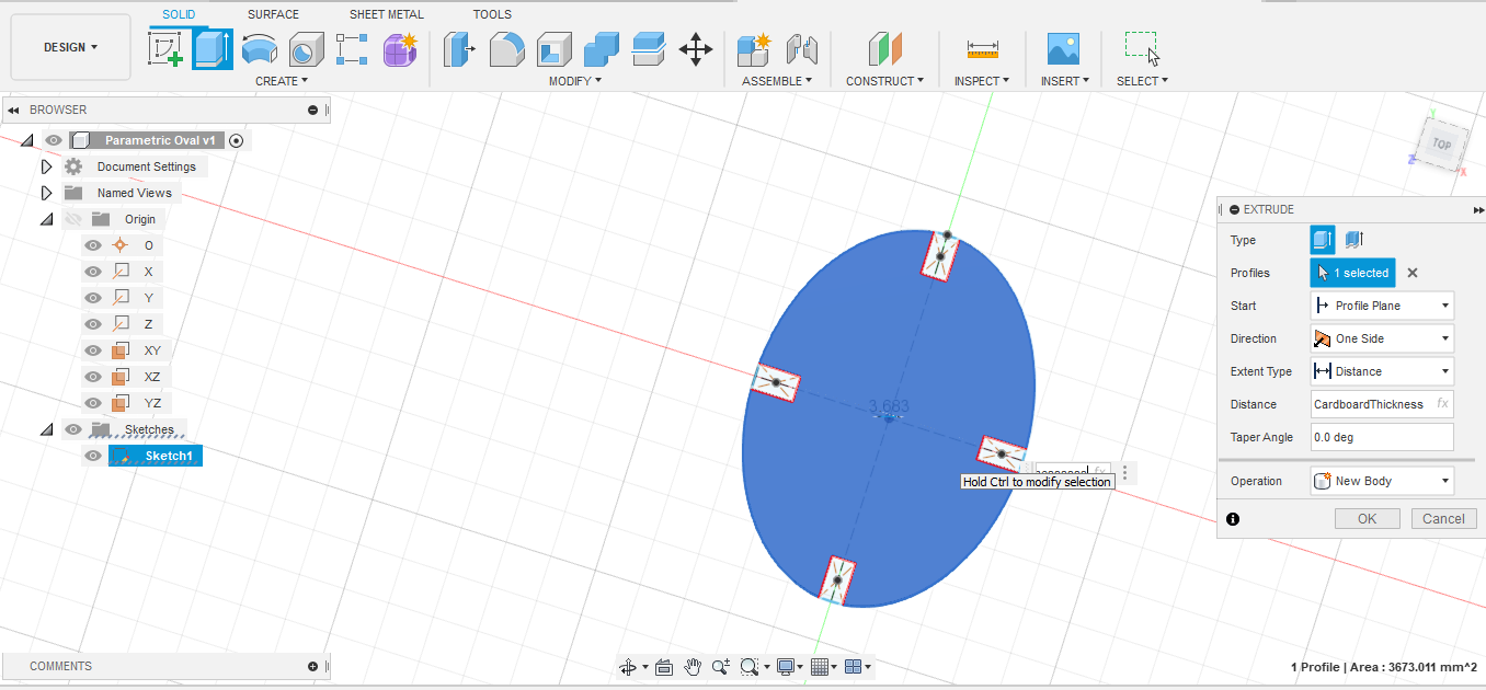
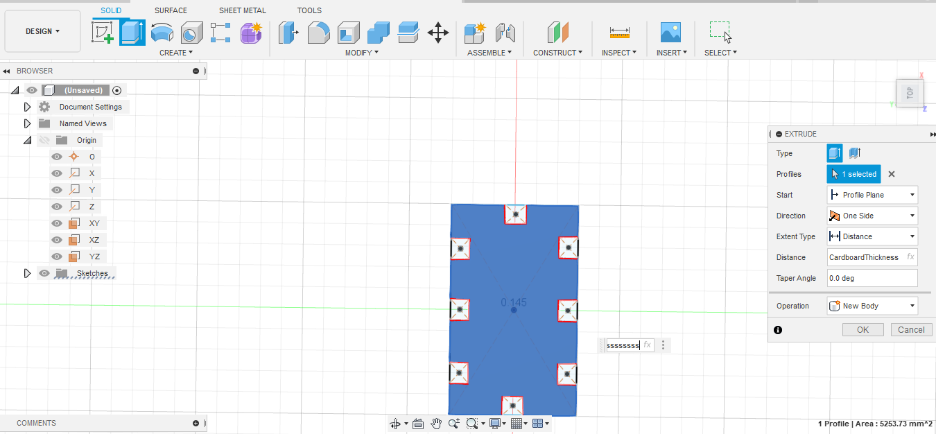
Then I extruded the oval using the Cardboard Thickness parameter.
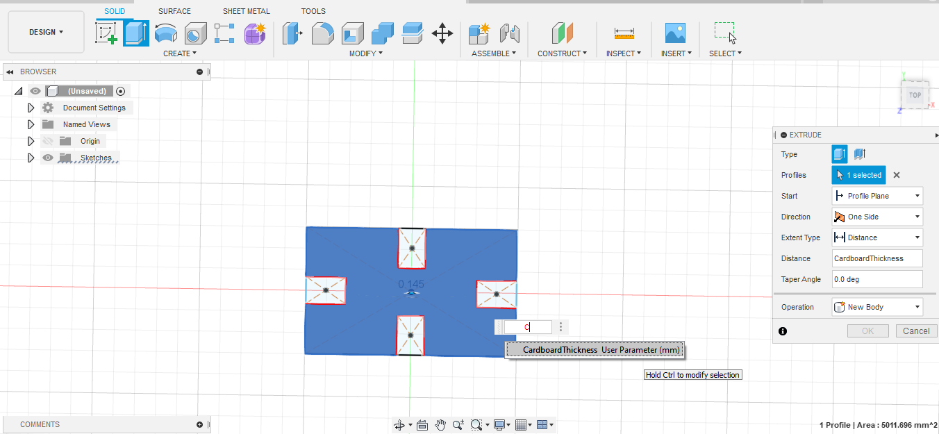
The rectangle was a similar process. I created a parameter called Depth, and set it to 60, so that it would be the same size as the oval. Then I extruded it to Cardboard Thickness as well.
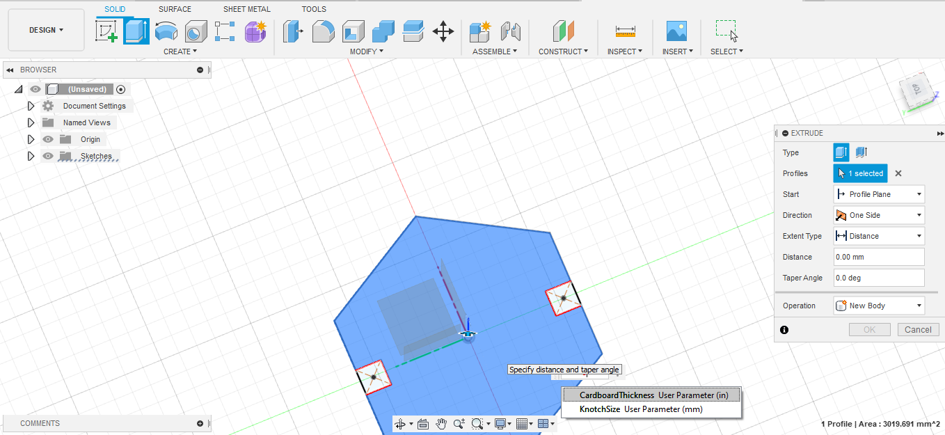
Then I started on the hexagon, which had three parameters: PolygonRadius, which was set to 30mm, KnotchSize, which was 7mm, and CardboardThickness.
Around 1am the next morning, I realized that the notches were not going to fit together. I had used the Notch parameter for the height of the rectangle, but not taken into account that the width of that rectangle would need to be the same as the thickness of the cardboard. I ended up setting the width of each notch to CardboardThickness as well.
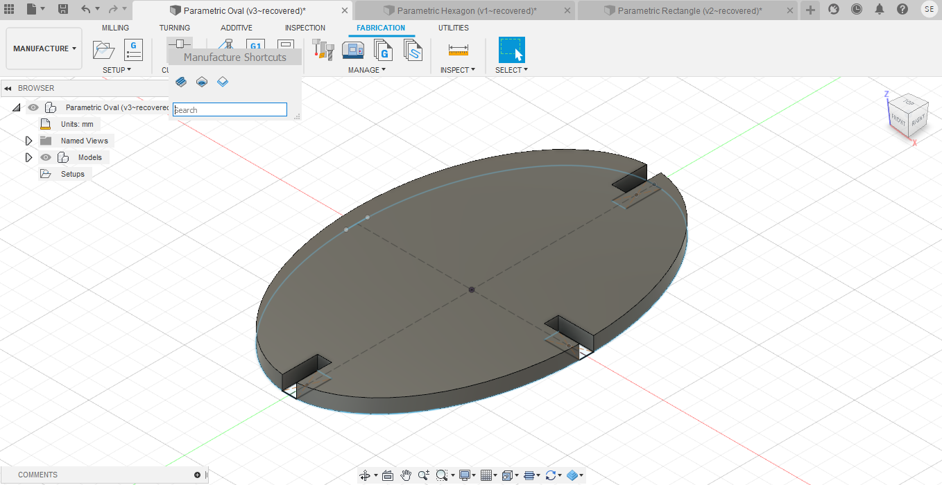
Then I was ready to cut the shapes. I started with the oval. I switched the mode from Design to Manufacturing.
Then I went to the Fabrication option, clicked on the Cutting, and selected Laser.
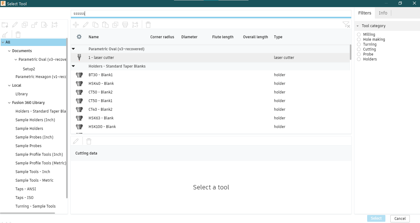
From there, I saved that as a file and opened the file in Adobe Illustrator.I copied the image so that there were 10 blocks total.
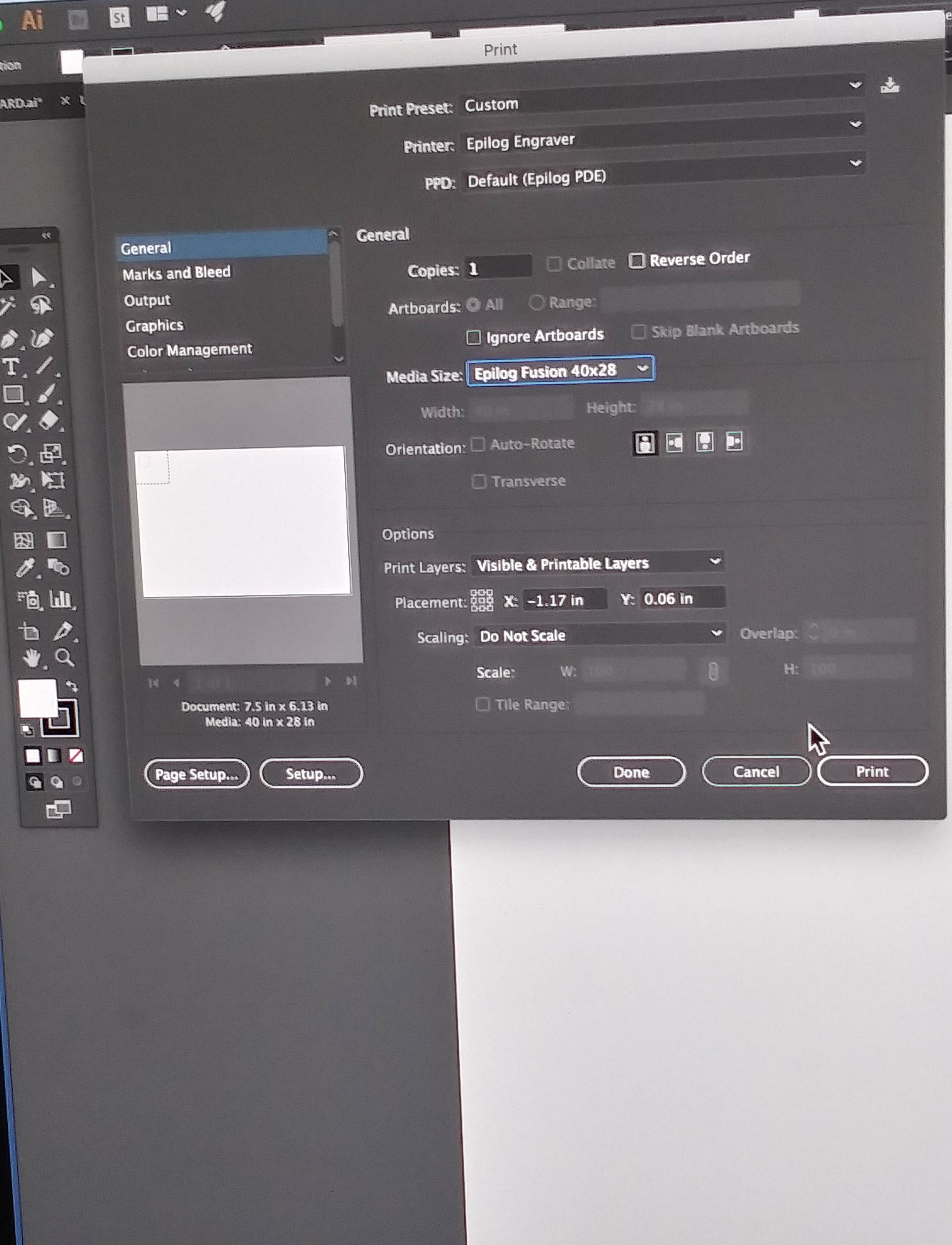
Then I turned on the laser cutter, focused the laser, and began to laser cut my ovals. Luckily, the notch was the correct size the first time around, so I didn’t need to recut anything.


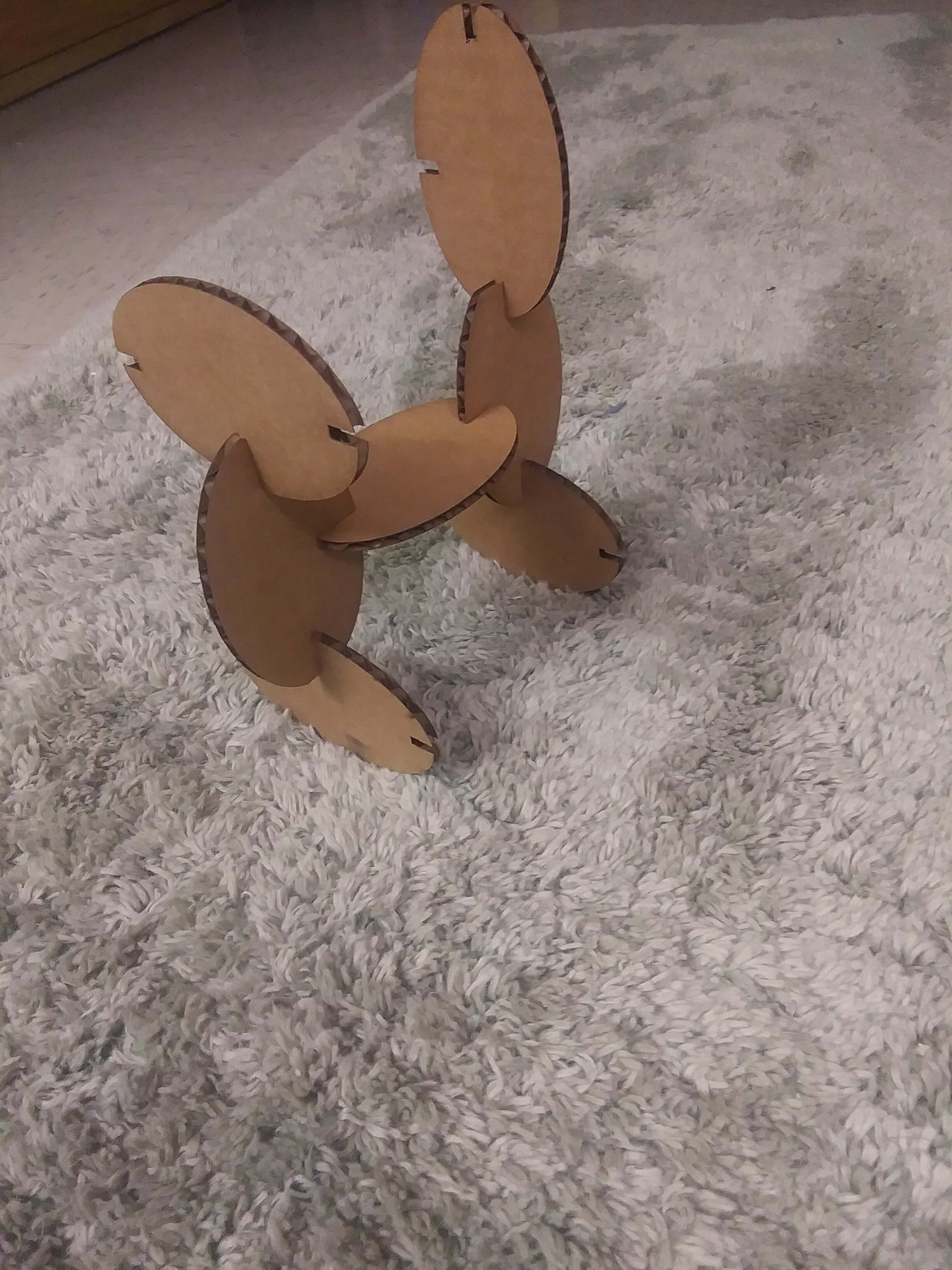
I fooled around a bit with my blocks and built a few random shapes.

My roommate also decided to use my blocks to make an abstract rendition of a dog.
Right after that, my computer decided to become finicky, and Fusion 360 crashed for some reason, so I ended up unable to cut the rectangle and hexagon during the time allotted for my laser cutter appointment. Consequently, I will end up cutting those at a later date.
Files
Affinity Vinyl Cutting DesignFusion 360 Rectangle
Fusion 360 Hexagon
Fusion 360 Rectangle