Input Devices
This week's material consisted of two parts: a group project and an individual project.
Group Project
The group assignment for this week was to explore different types of sensors. After listening to a lecture given by our professor about the general categories of sensors, my group went into Tinkercad and played around with different types of sensors. We looked into potentiometers, which have three terminals and a wiper. Potentiometers are used to control things like volume, because it allows for gradual adjustment. Our group made a circuit combining a potentiometer and a photoresister. We put a wire going from VCC to the positive section and another from GND to the negative. Then we attached wires going from the input devices to their respective programming pins.Finally, we added a resistor to each, and connected each sensors with wires to the positive and negative terminals.

Then we wrote a code to print out the values of each sensor as the input strength changes.

Individual Project
In this week's individual project,the assignment was to create a board that contained an input device. My final project is going to be a smart diffuser that takes input from a hygrometer, so I figured it would be a good idea to begin becoming familiarized with similar types of input devices. I found an Arduino Temperature and Humidity Sensor that served a similar purpose, and decided to design a board that will use the sensor as input.

Because I am still relatively new to electronics design, I like to test everything out in Tinkercad before I jump into anything else. Tinkercad has a circuits section that is essentially a simplified online breadboard. I find it very handy while just starting out a new project, because it forces me to ensure I have a strong enough understanding of the mechanics of the circuit I am about to design before I attempt to build it. Using Tinkercad, I used an Arduino and a breadboard and attached a wire from 5V (VCC) to the positive section of the breadboardand another wire from negative to Ground (GND). Then I added a temperature sensor and a resistor. From there, I connected the temperature sensor's power side to the resistor, and the other to negative. Than, in order to be able to program the sensor, I connected the sensor's Vout to Analog Pin A0.

Then I began coding the Tinkercad model. I made a simple program to read the input that the temperature sensor was sending to A0 and print out the values.

The code ran and got the anticipated values, so I went on to build the circuit in Arduino in real life. I used an 1000 Ohm Resistor, a couple of wires, the Arduino, and the Temperature and Humidity Sensor. Then I recreated the circuit I had designed in Tinkercad in real life. Thankfully, it worked and both of the lights of the Temperature and Humidity Sensor turned on.

From there, it was time to begin the actual design. Although I did add components of my own, as well as change a few connections around, inspiration and guidance for this design was taken from the Hello Echo Board that I linked to in Week Six. In creating the schema, I added an extra resistor and a 3 pin connector to attach the sensor to. I also added a connection to the analog pin on the AtTiny 1616 that I would be using to program the sensor.
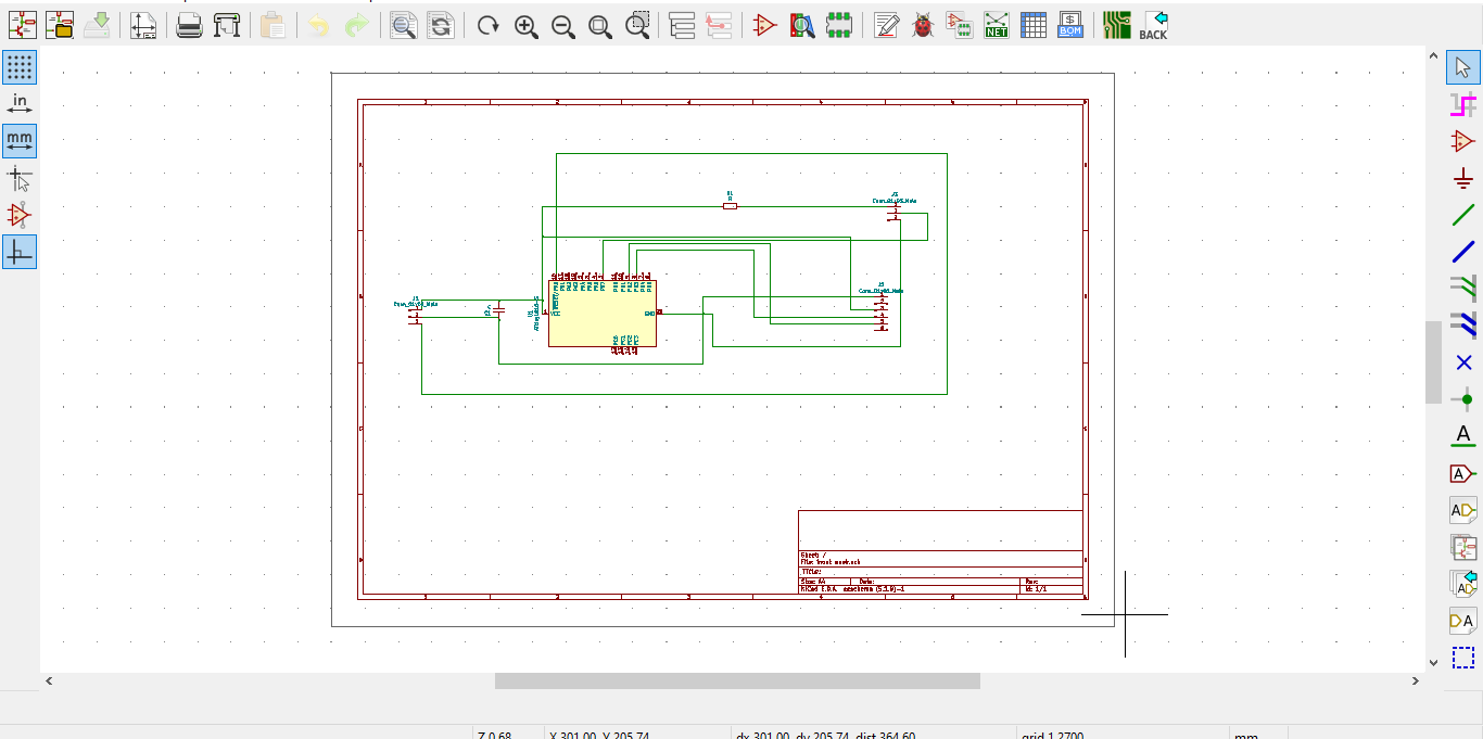
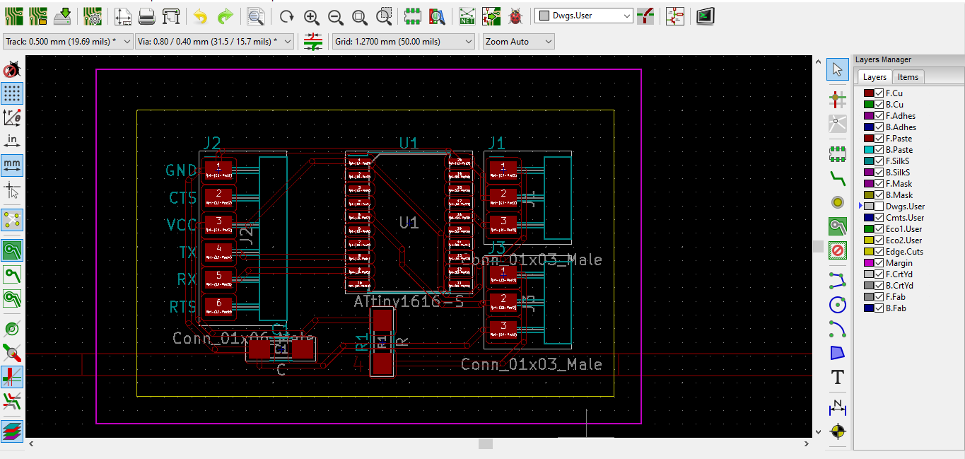
Once I finished up the schema, I began to hand route all of the wires. I spent a good twenty minutes playing around with pathways, trying to find an orientation that would work. After a while, I decided that routing it felt impossible. Appearently it actually was impossible. I ended up downloading Freerouter, which is an autorouter software that wires everything for you. Freerouter ended up figuring out how to wire my board, but only after moving a couple of connecters and rotating the resistor.

Then, I moved that file back into Kicad and used the line and polygon tools to create the outline and margins.
I turned the margins and traces into two separate SVG files and put tem through MODs


MODs turned each file into an RML, which I was then able to use on the Roland Mill.


Then I soldered all of the components on. At one point in the soldering process, I was scraping excess solder paste away with tweezer and accidently disconnected part of the copper. Luckily, it was very little, so my mistake was able to be remedied with some copper wire and solder.

I ran a quick continuity test, and everything turned out fine. That meant it was time to program the board. I put a link to the code below. I first needed to install the library for Temperature and Humidity Sensors.
Then I proceeded to hook the board up to my computer and the Temperature and Humidity Sensor.

After that, I compiled and uploaded the code successfully.

Both of the light on the sensor turned on, implying that it was working. (the bottom light isn't easily visable in this photograph for some reason, but I reassure you it is on)

I went into Serial Monitor to make sure it was working using the code I linked to below. The sensor was connected, but not functioning properly, as it was reading everything as 0 Celsius and at 0% humidity. This is an issue with the sensor itself, not the board.

Links
Mods Traces.svg)
Kicad Footprint
Humidity Sensor Library
Arduino Code