Electronics Production
Group Project
For this week's group assignment, our group needed to characterize and test the properties of a Roland SRM20. We started out by defining a few essential terms.
Feed rate is how fast the endmill moves in relation to the stock defined in distance and time or in distance and revolution.
Spindle speed is the rotation frequency.
Plunge Rate is the rate at which the endmill lowers into stock when cutting (distance/time)
Depth of Cut is the total distance to cut into stock
Tooling is the process of designing and engineering tools used to manufacture components
Specifications
Max Tool Size: 1/4" or 6mm
Spindle Speed: 3000-7000 rpm
Operating Speed: 1.18 in/sec or 30mm/sec
Power: 110V / 2.5A
Work Area: 8" x 6" x 2.38"
Feed Rate: 203.2 (X) x 152.4 (Y) x 60.5 (Z) mm
Power Consumption: Approx. 50W
Group Milling
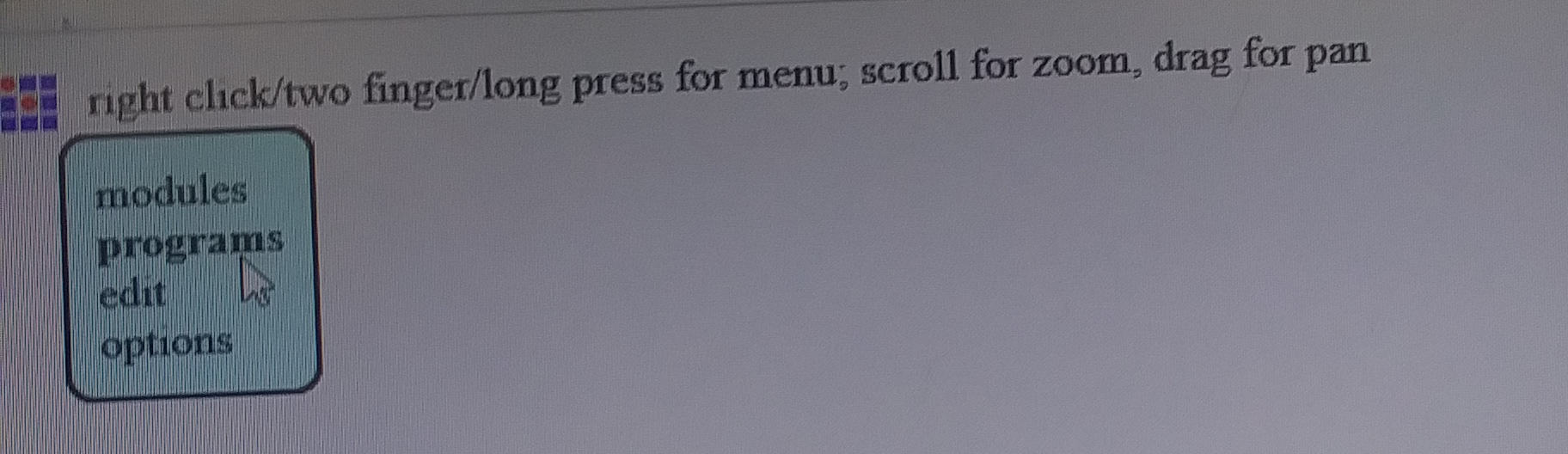
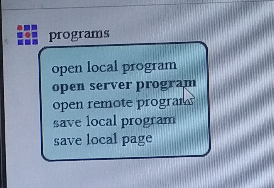
Our group was asked to mill a board demonstrating the Roland Mill's cutting abilities, as well as it's precision. We went to Fab Academy's website and downloaded a test file off of the Tutorial page. Then we went to Mods, right-clicked and selected Programs, chose Open Server Program, then went under the SRM-20 heading and selected PCB png.

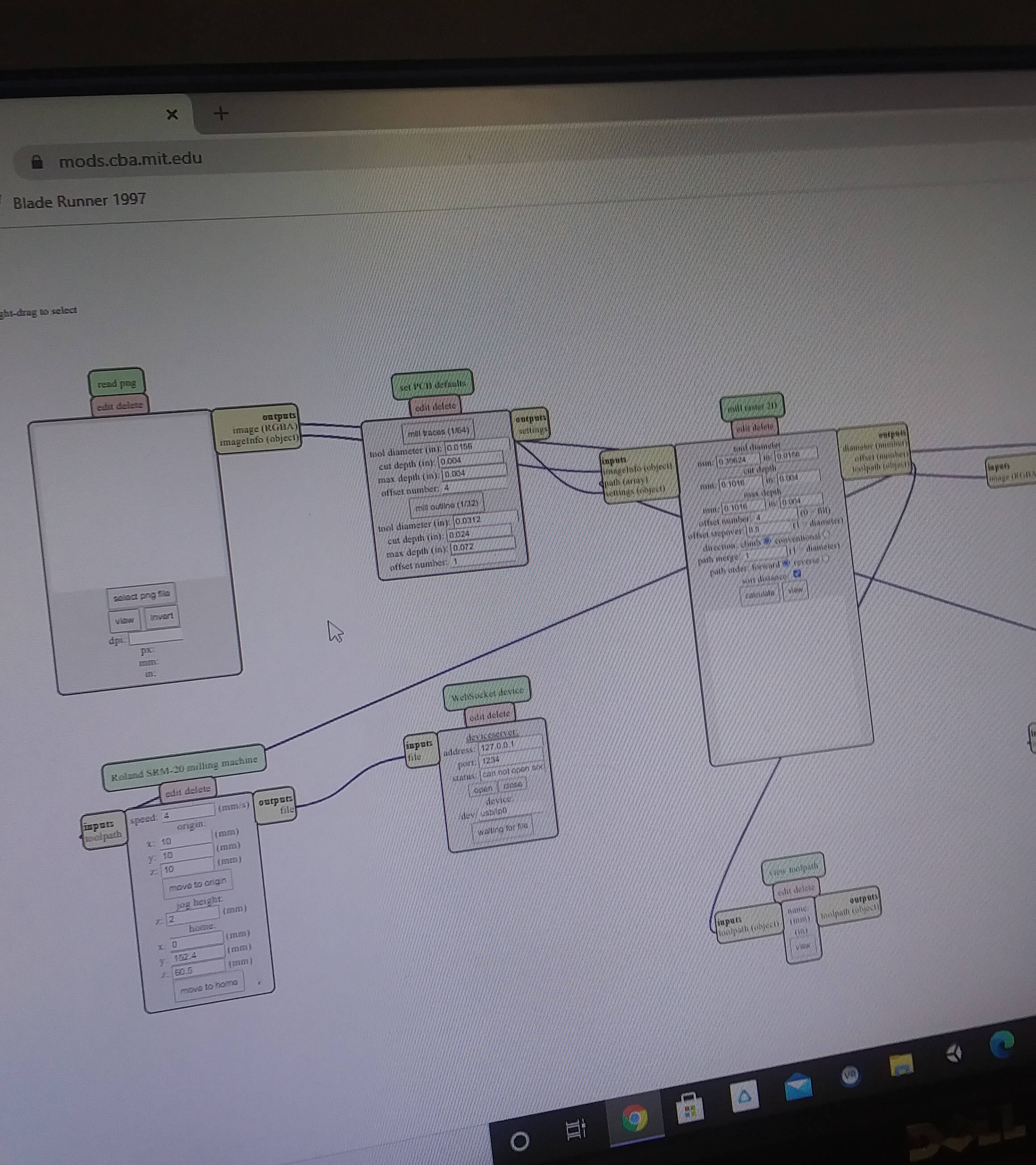
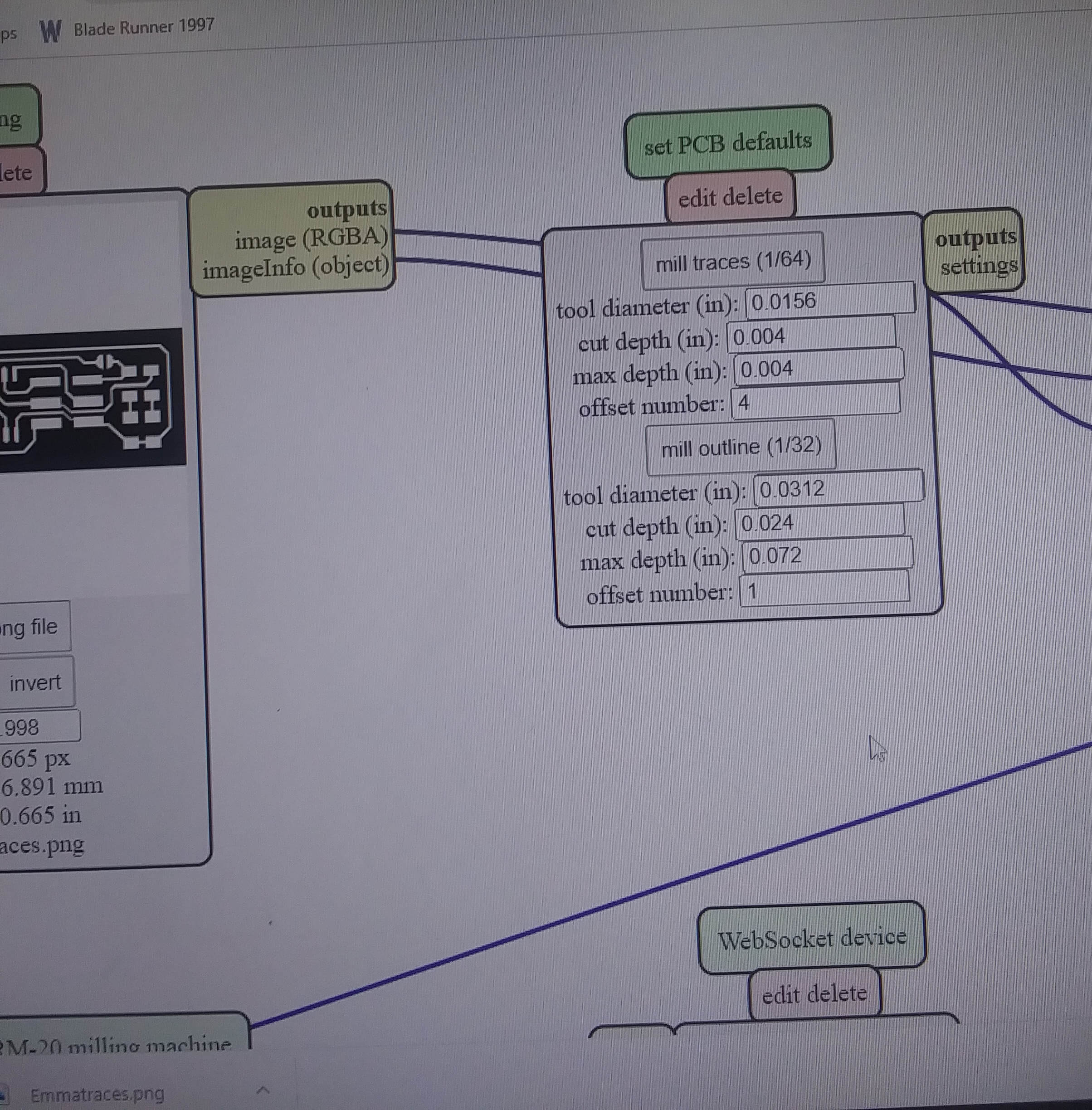
From there we put in the PNG file we had downloaded and set Mill Traces to 1/64.
We saved that as an RML file. Then we connected WebSocket Device's inputs file to Roland SRM-20 Milling Machine's (the mill's) outputs file.
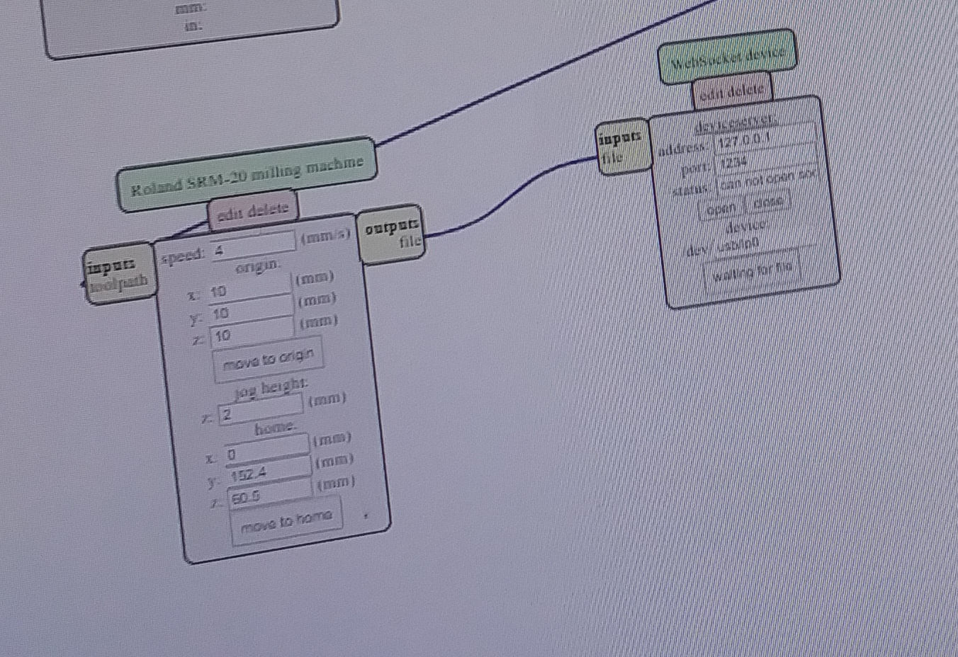
Then we changed the X, Y, and Z axis to zero.

We saved that file on a USB, which we used to transfer the information to the computer connected to the Roland Mill.
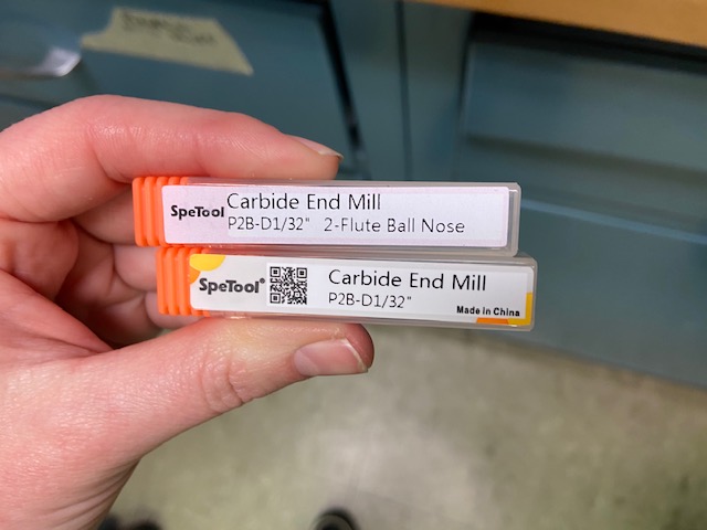
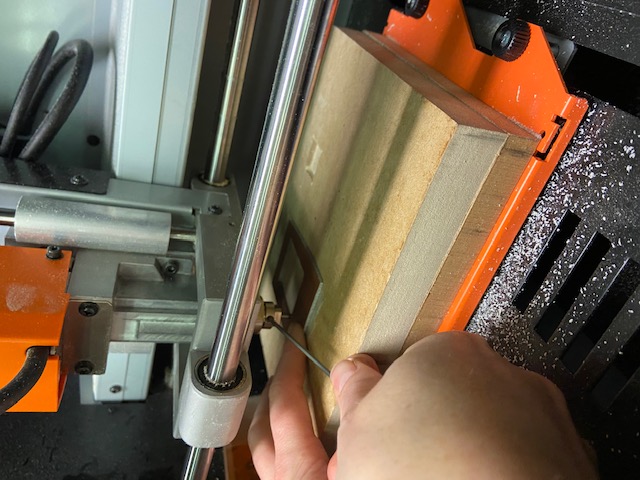
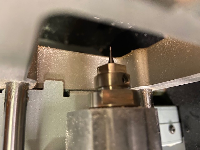
Then we were ready to mill! To start, we used the Flute Ball Nose to make the traces. The Z axis was set by lowering the bit down untio it was just above the middle of the PCB, then loostening the screw holding it in so it could fall a couple millimeters to touch the surface of the board and screwing it in again. After that we raised the bit again and set the X and Y axes in the bottom left-hand corner. We zeroed that as well.

Once that was finished, we set the speed to 20 millimeters/second and selected the cut button.
The mill finished, we vacuumed up the debris with the shop vacuum, and we used the Carbide End Mill bit to completely cut out the board. Because our speed was set very high, our group had initially hypothesized that the board would come out sloppy, but most of the cuts were more precise than anticipated. We found that the cuts were all very clean, up to around the 15" mark, at which point it gets increasingly sloppier.
Individual Milling
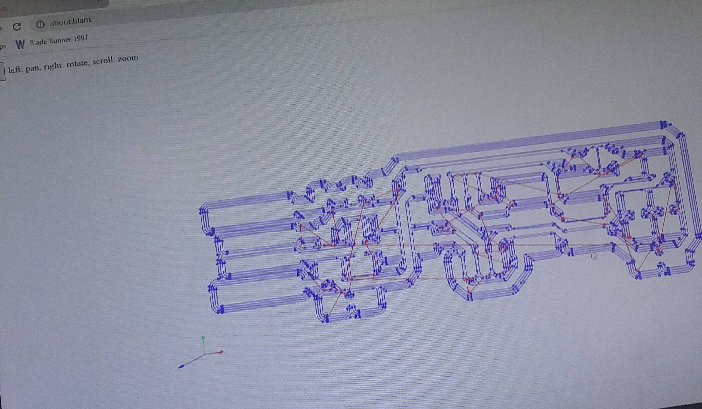
For the individual assignment, I made a FabTinyISP, which is essentially a computer that can program other computers. I used the file from Fab Academy's Tutorial page for the cutting and tracing model. The process was pretty similar to that of the group assignment. I went into Mods and input that file. I decided to look at a map of the tracing before I began the milling.
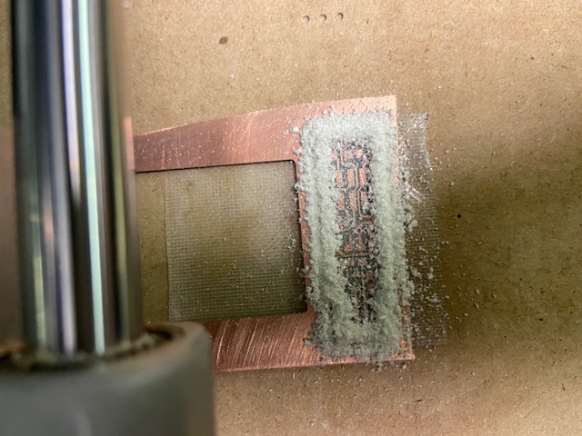
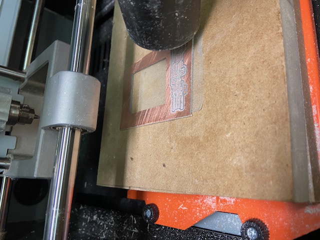
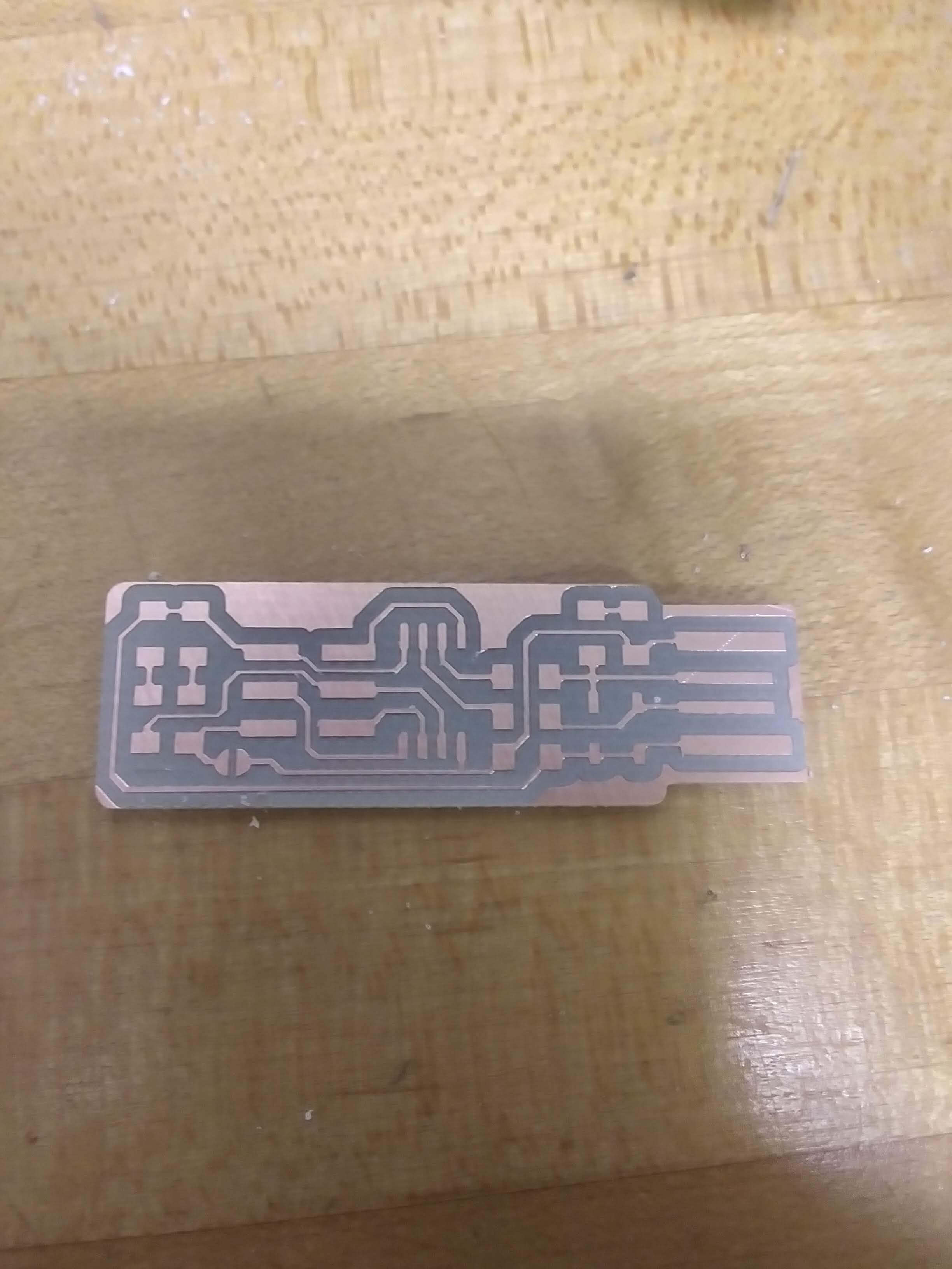
From there, I moved the file to the computer connected to the Roland via USB. I used the same process to zero the X, Y, and Z axes as before. Then I traced and cut the board and vacuumed the residue.
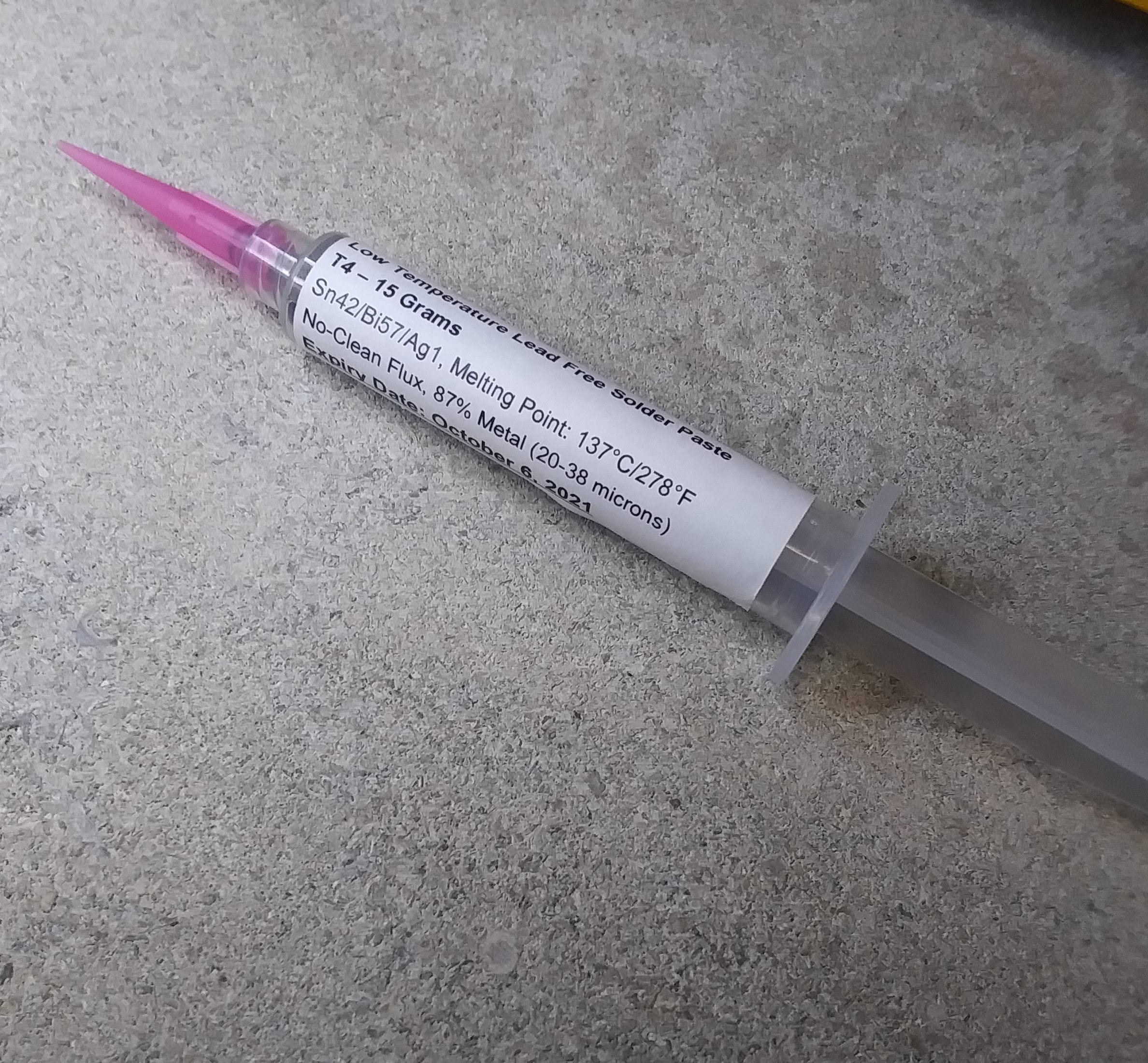
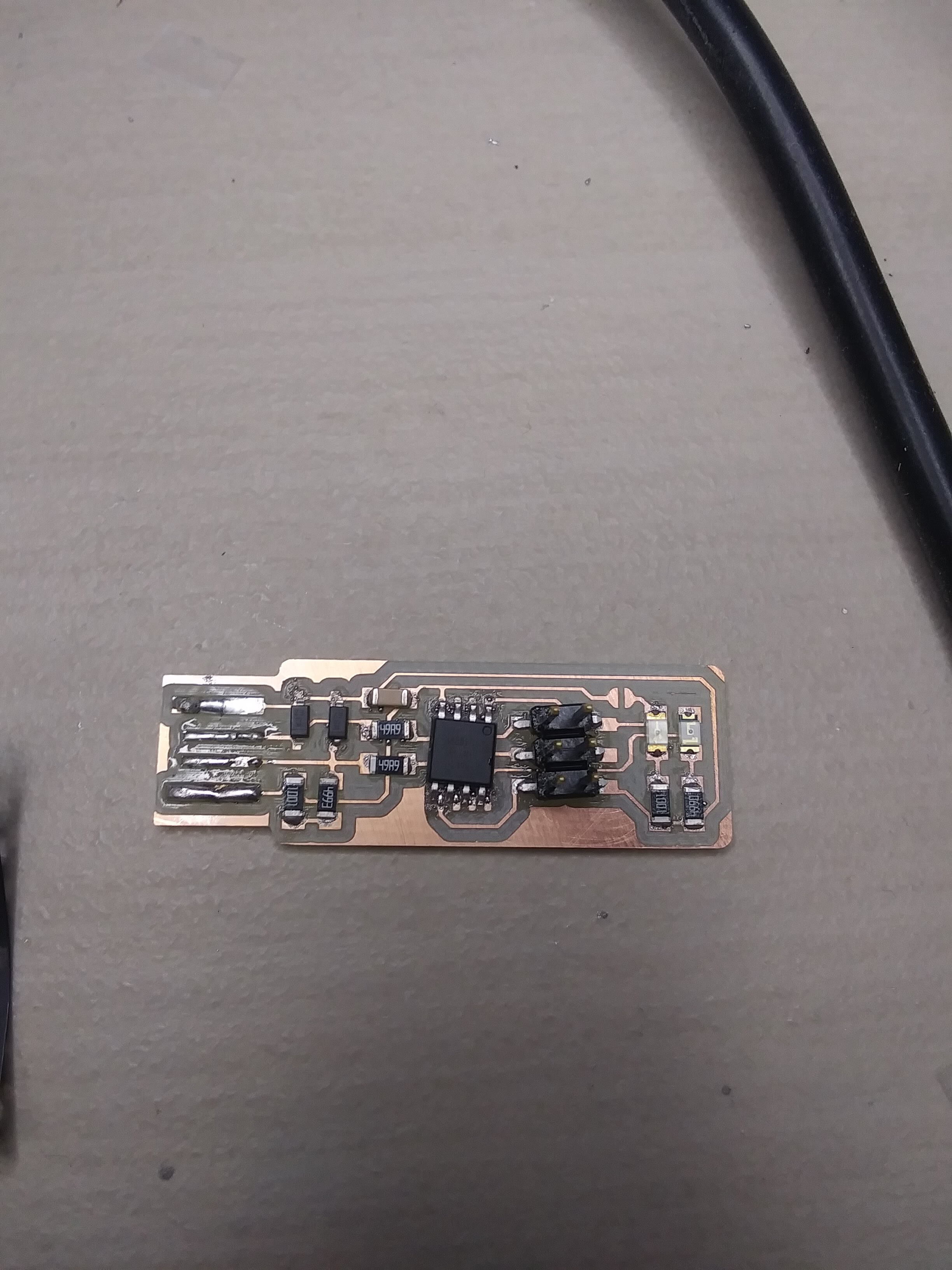
Soldering
Once the PCB board was milled, I got ready to solder all of the electrical components on. This was my first time soldering, and I found it surprisingly fun. Soldering is essentially taking a solder paste, which consists of an alloy with a low melting point, and using heat to turn it into a sort of glue to attach electronical components.
The Fab Academy Tutorial page has a map for all of the electronic components that go on the PCB board.

The electrical components needed for the FabTinyISP include:
1x ATtiny45 or ATtiny85 2x 1kΩ resistors2x 499Ω resistors
2x 49Ω resistors
2x 3.3v zener diodes
1x red LED
1x green LED
1x 100nF capacitor
1x 2x3 microcontroller
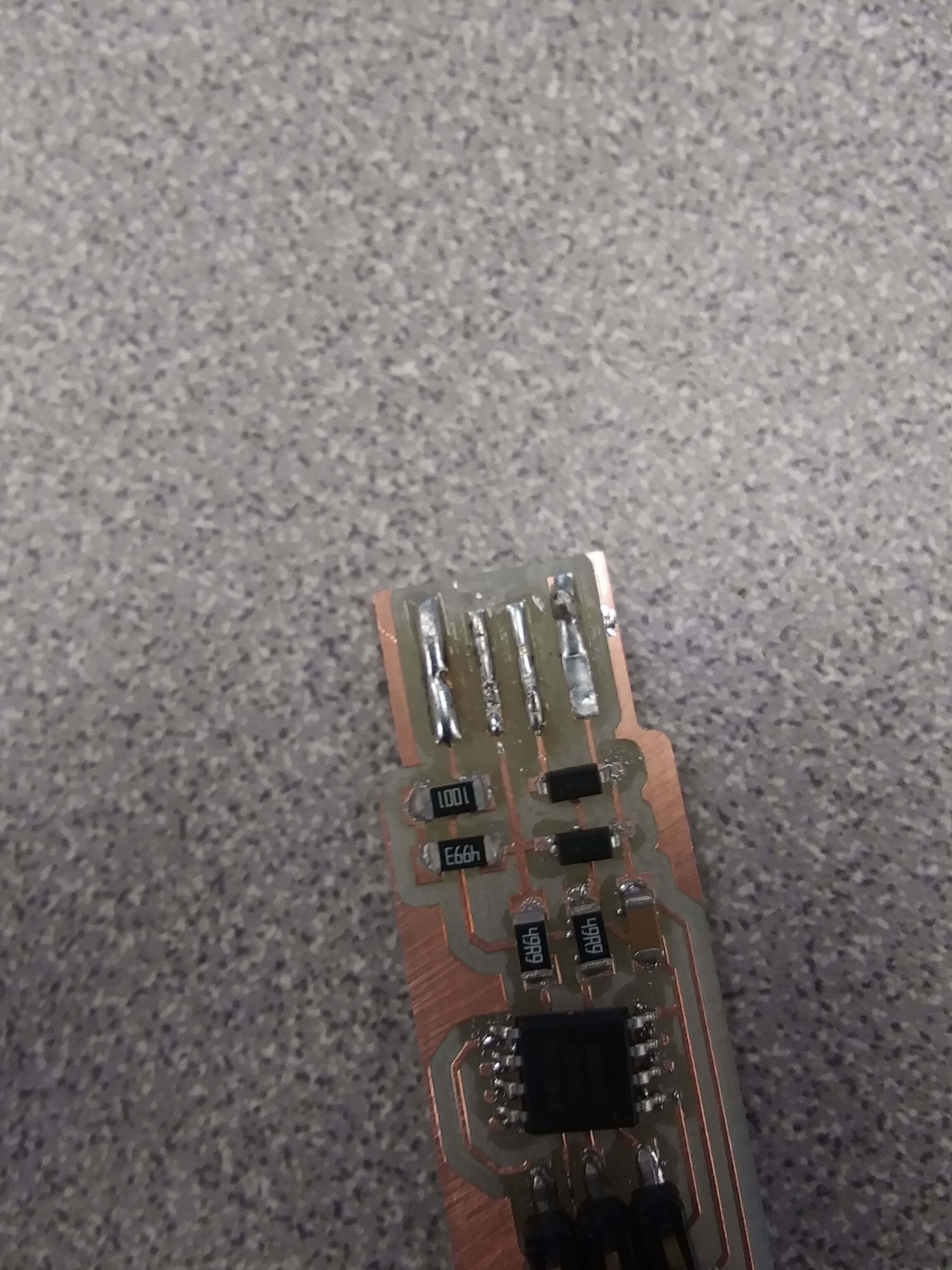
I got all of these pieces and used a heat gun to solder them to my board.
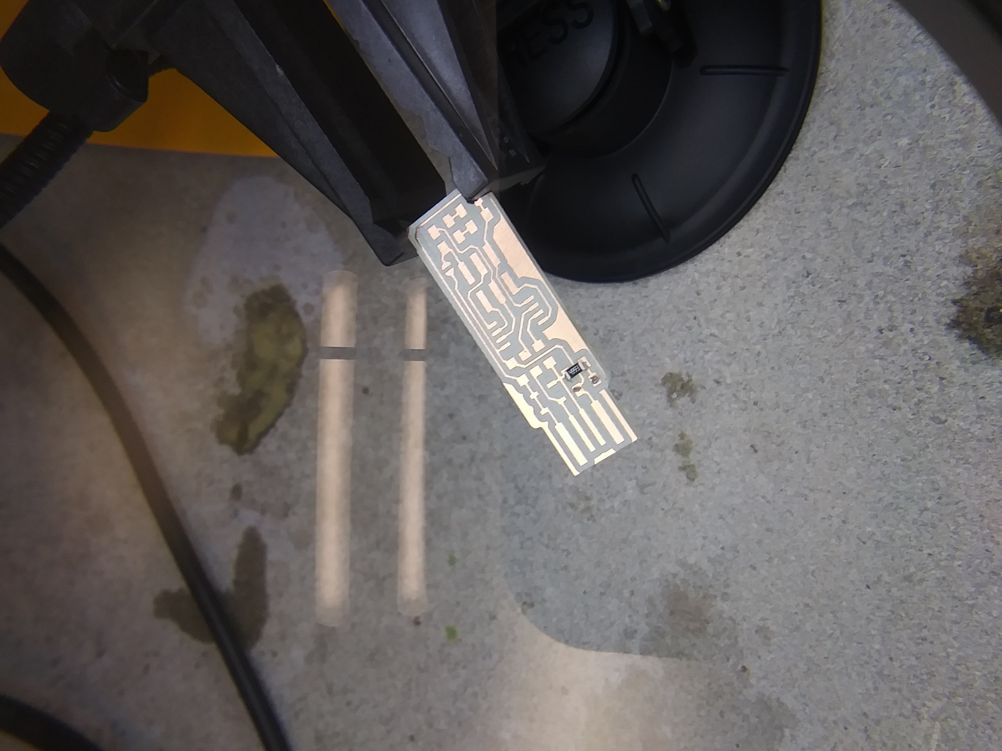
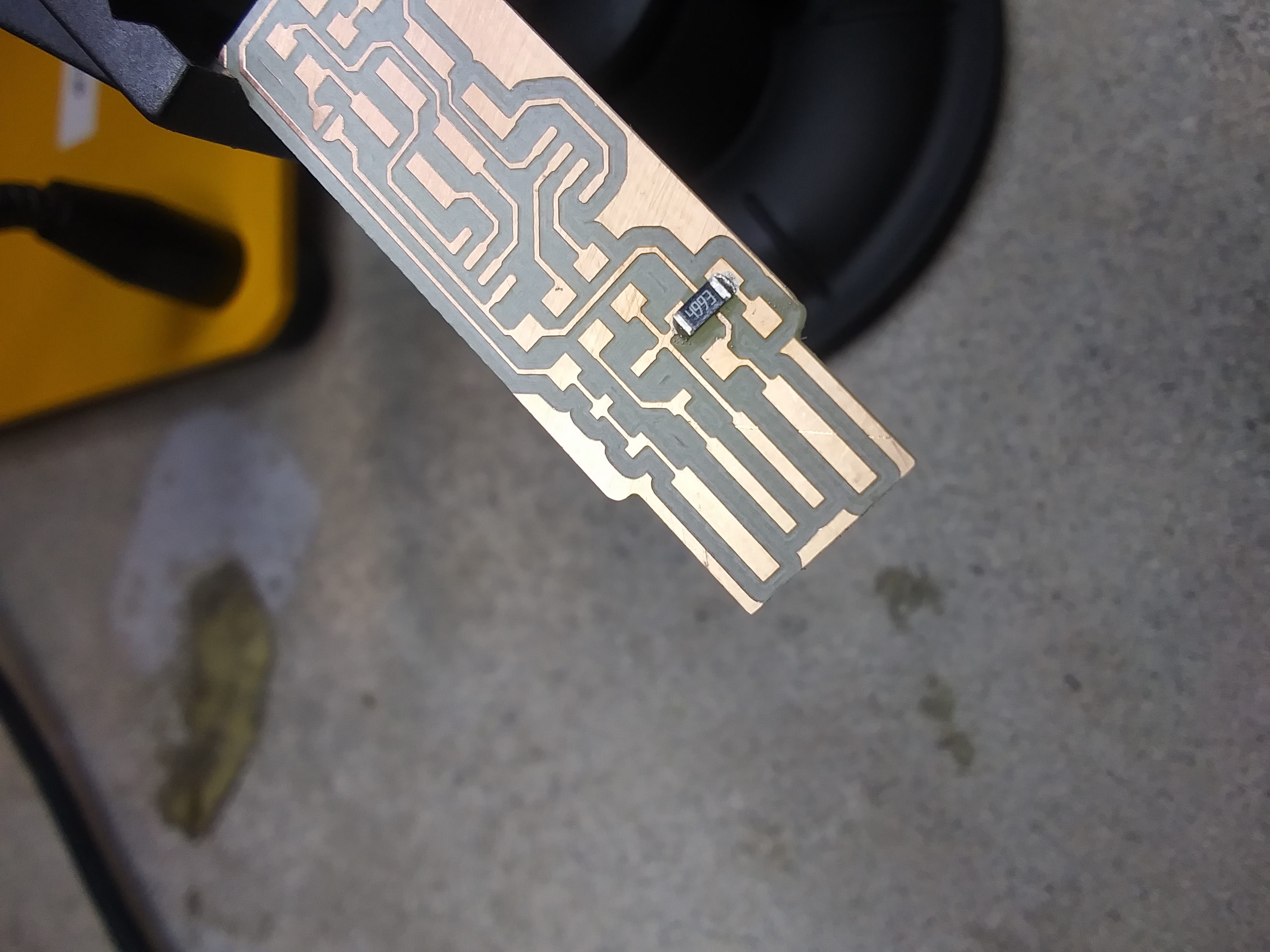
Between each piece, I tested the continuity to make sure that everything was correctly attached.
I continued that until each piece was securely on the board.
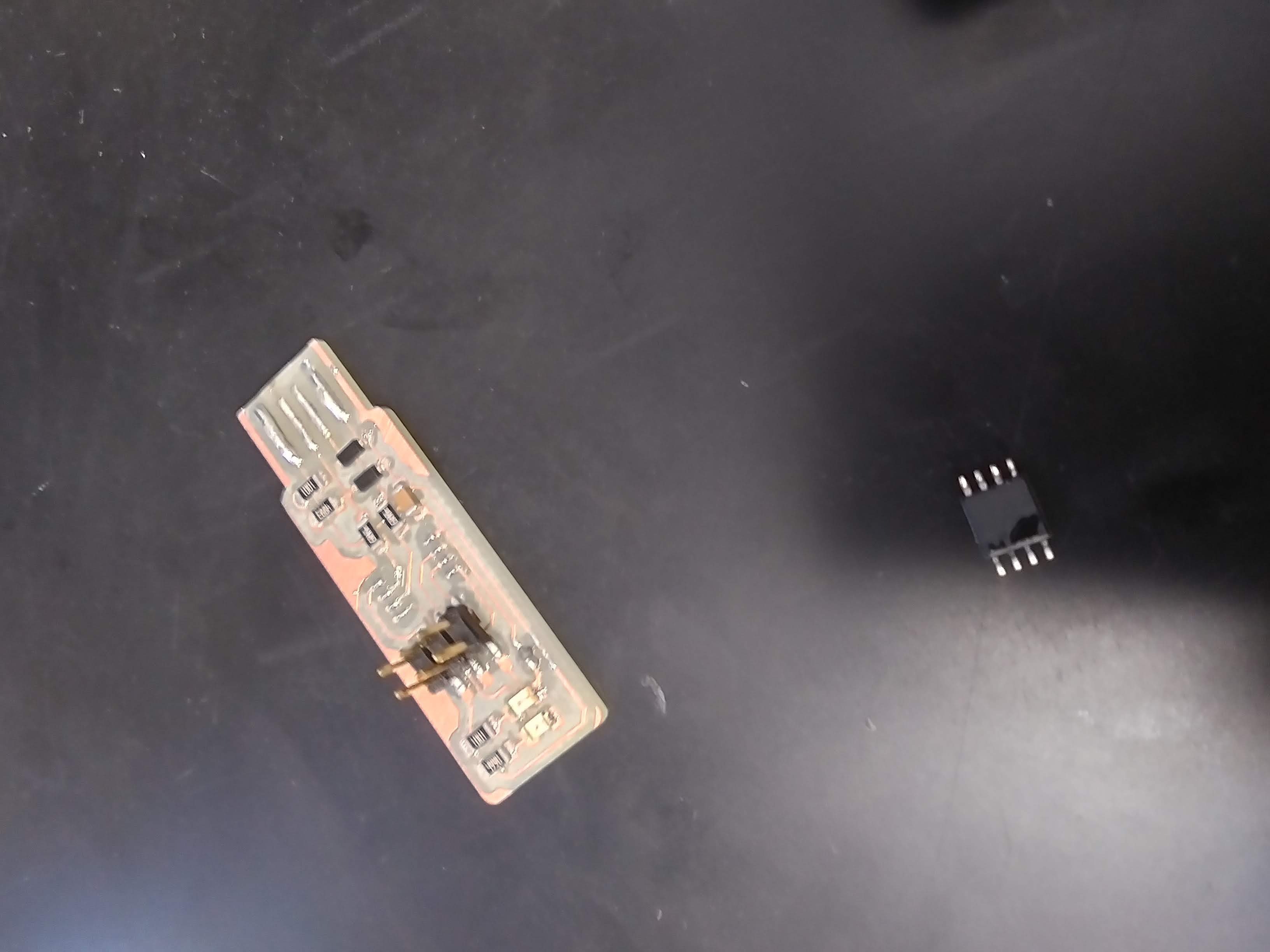
Programming
Once my board was soldered, it was time to program. I started this out with a mistake: my microcontroller was not correctly on the copper, so I had to resolder that. Then I plugged it in to the USB drive again. This time, there was quite a but of smoke. I quickly removed the board, and the microcontroller flew off. It was slightly melted and unusable. Luckily, the computer did not suffer any damage.
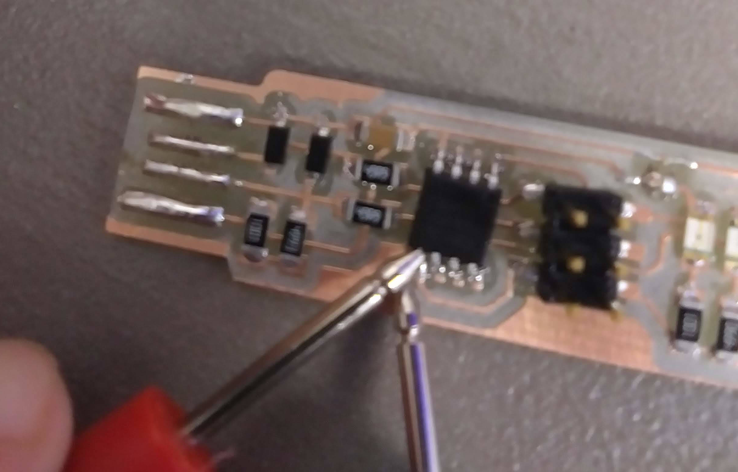
Appearently, when I had resoldered my board, there was a lot of solder that was not removed, and it ended up connecting each of the legs of the microcontroller. I cleaned that up, ran a thorough continuity test, and plugged it in again. This time there was no smoke.
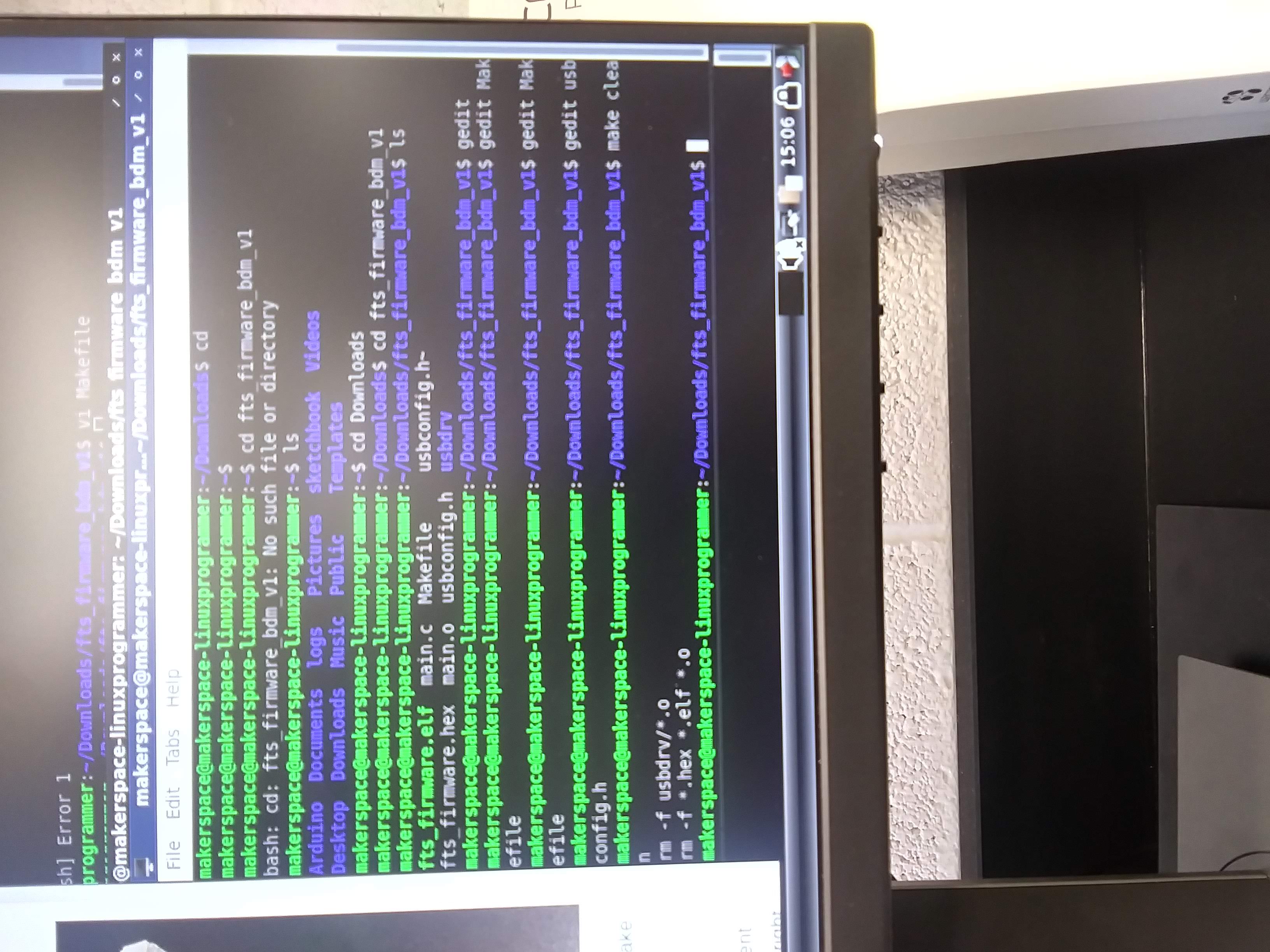
Then the official programming was able to begin. I followed the Fab Academy Tutorial for this as well. I used Linux. I went to downloads and ran make, which created the file I needed.
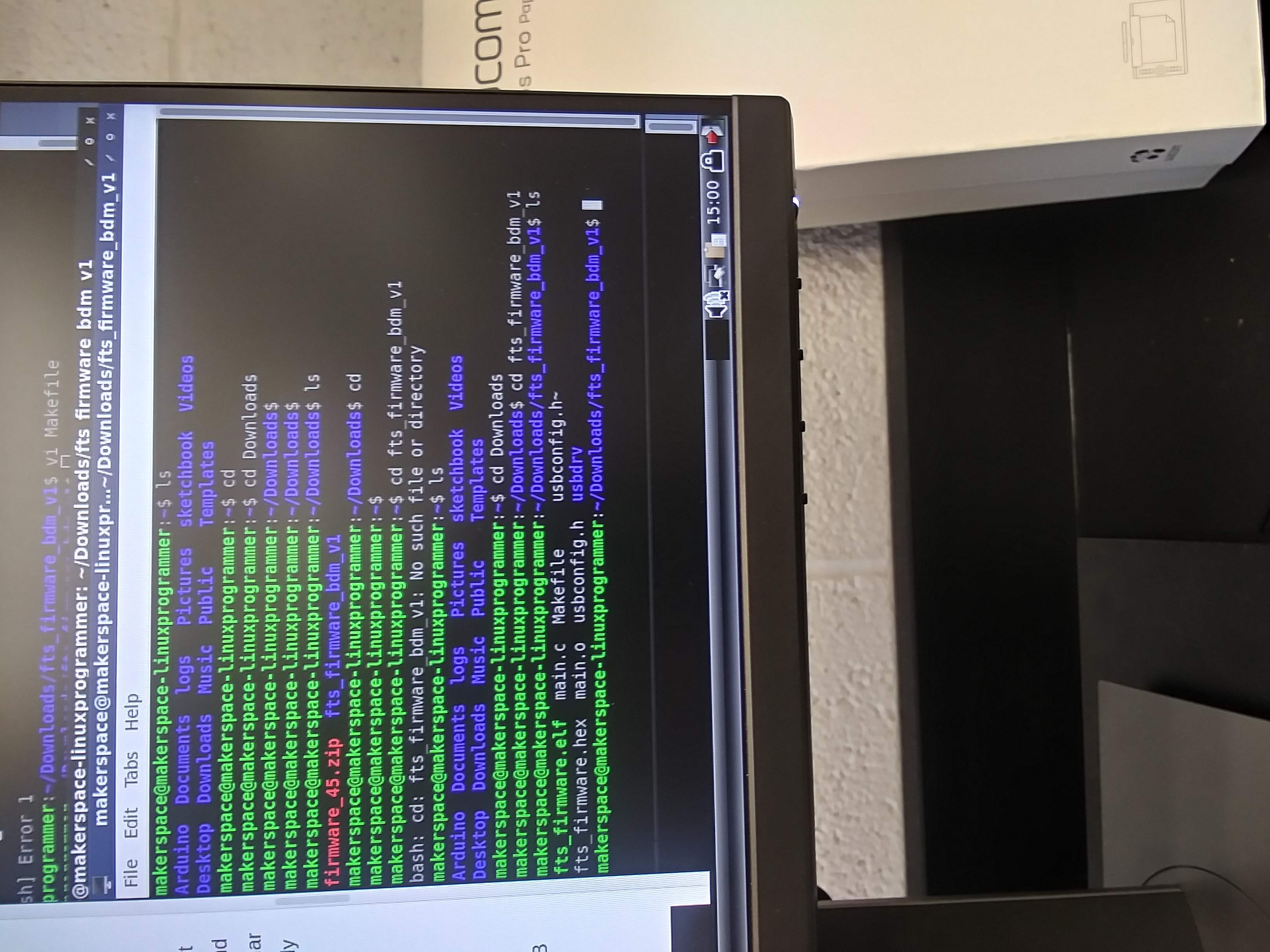
Then I went to MakeFile, usbconfig, and make clean, so I would be able to put the information from another person's FabTinyISP onto it.
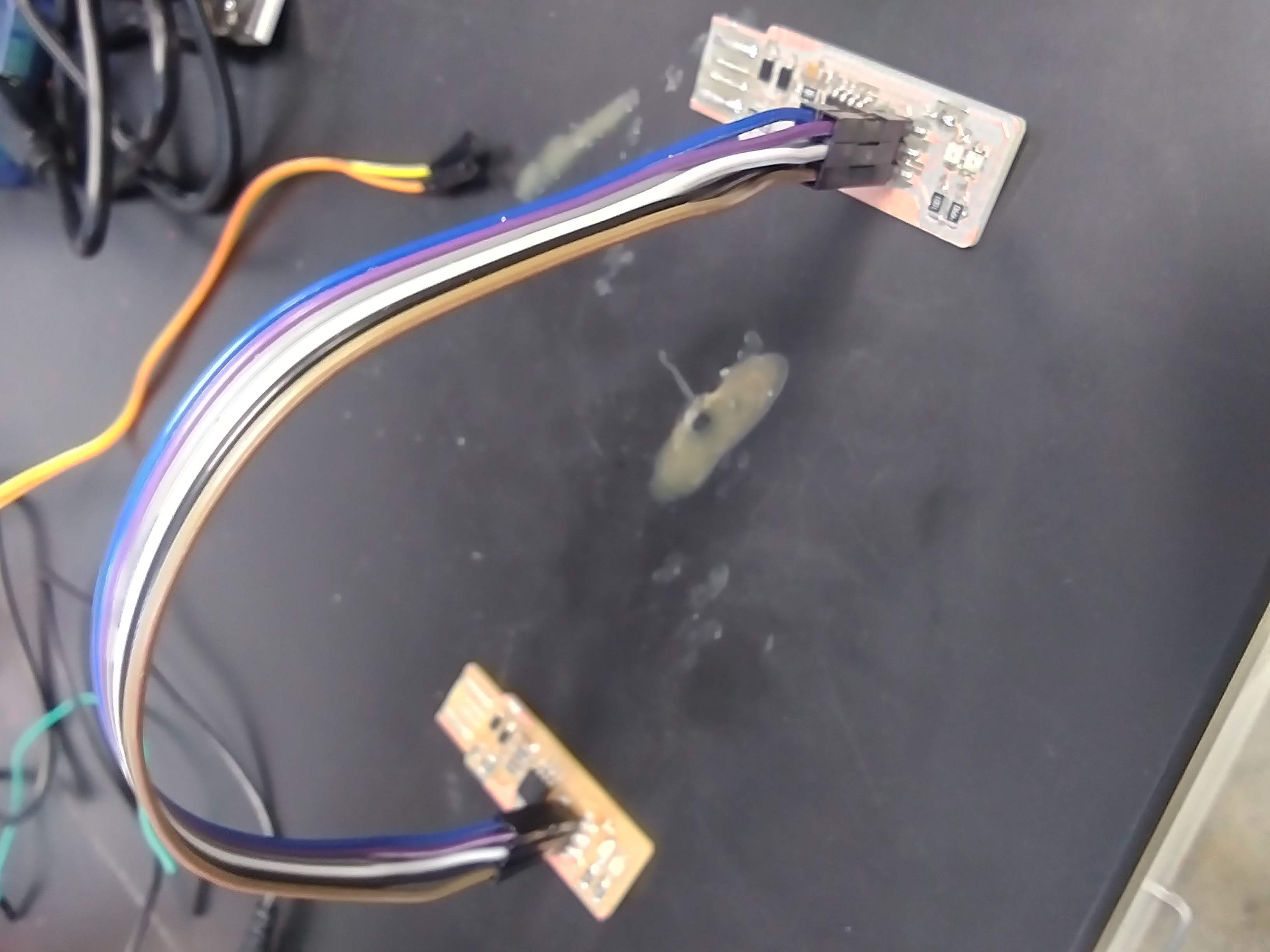
I connected my board to the board that would be transferring information to my board.
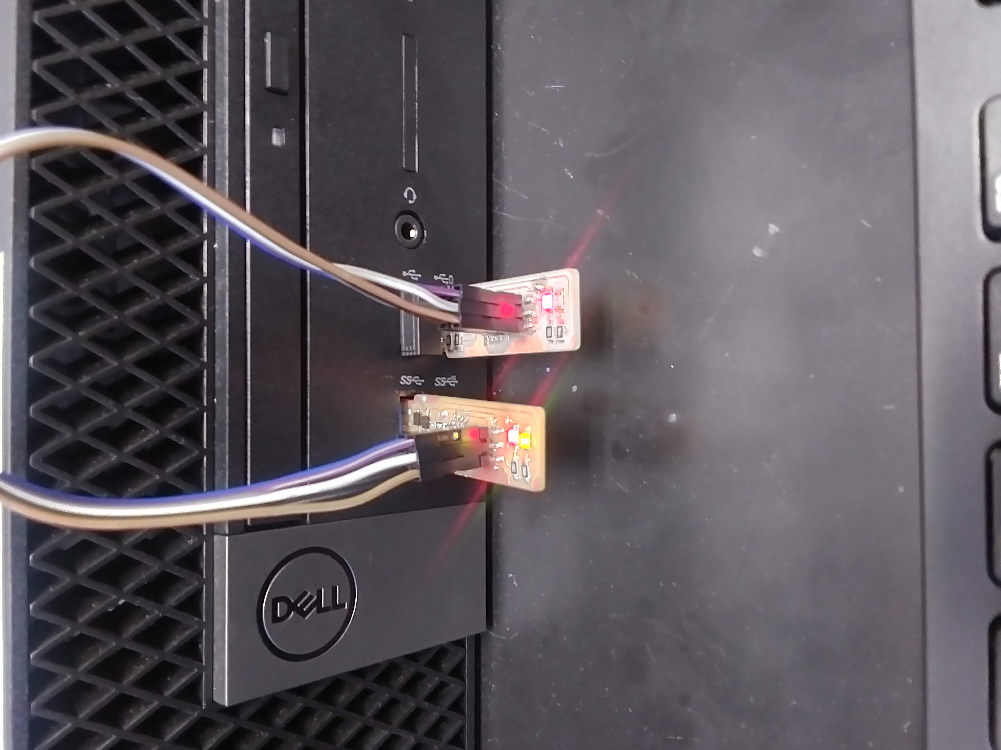
I plugged those both into the USB drive (there was no smoke this time!) and the LEDs lit up on both of the boards, implying that data was being transferred.
Then I went back and double checked that my board was successfully programmed. It was!
I typed in the lsusb command to make suke sure it was recognized by the computer. Becuse the solder lines were a bit asymmetrical, I did have to attempt this several times before the usb was situated correctly. Eventually, it did show up as "Multiple Venders USBtiny."
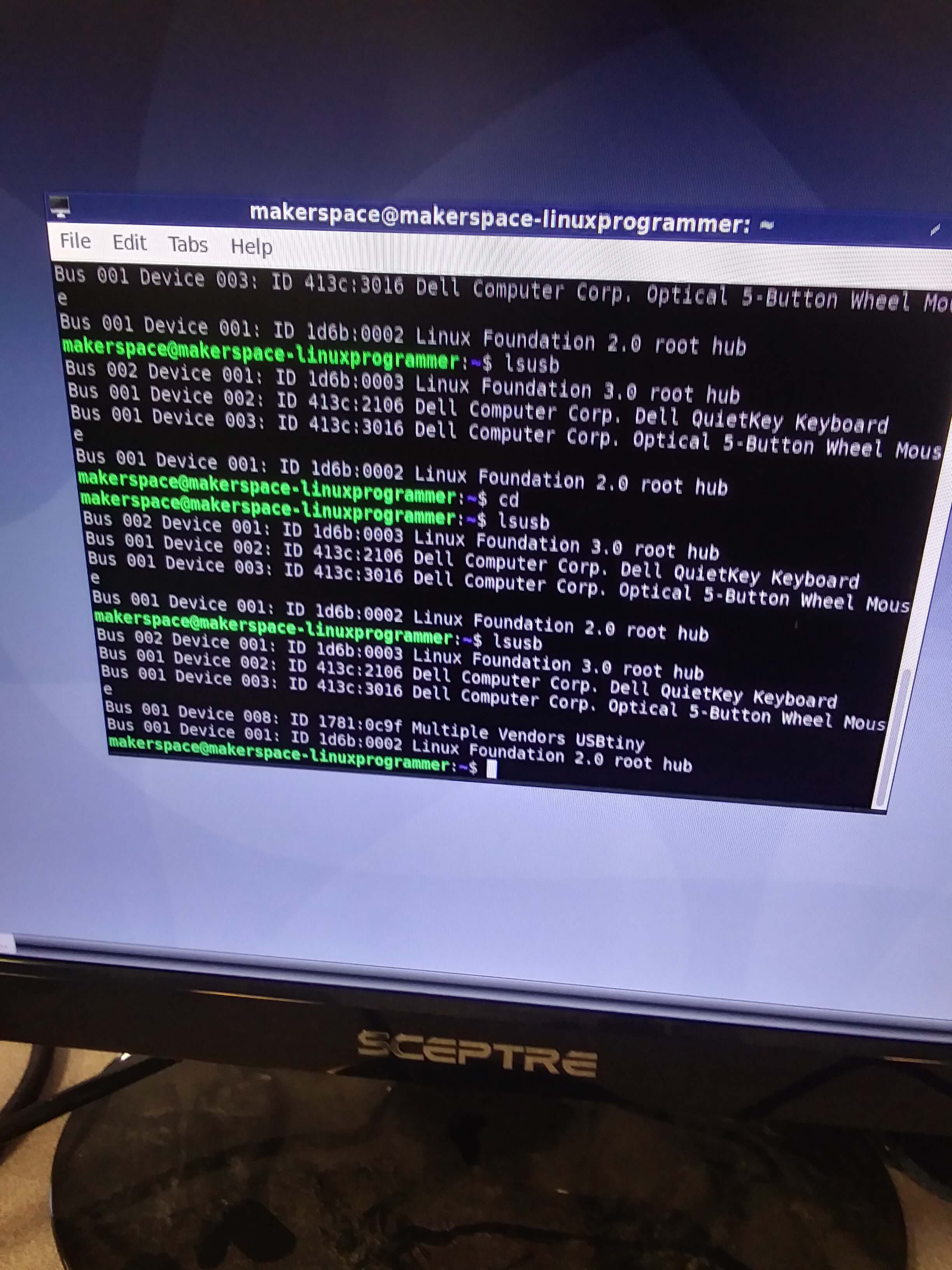
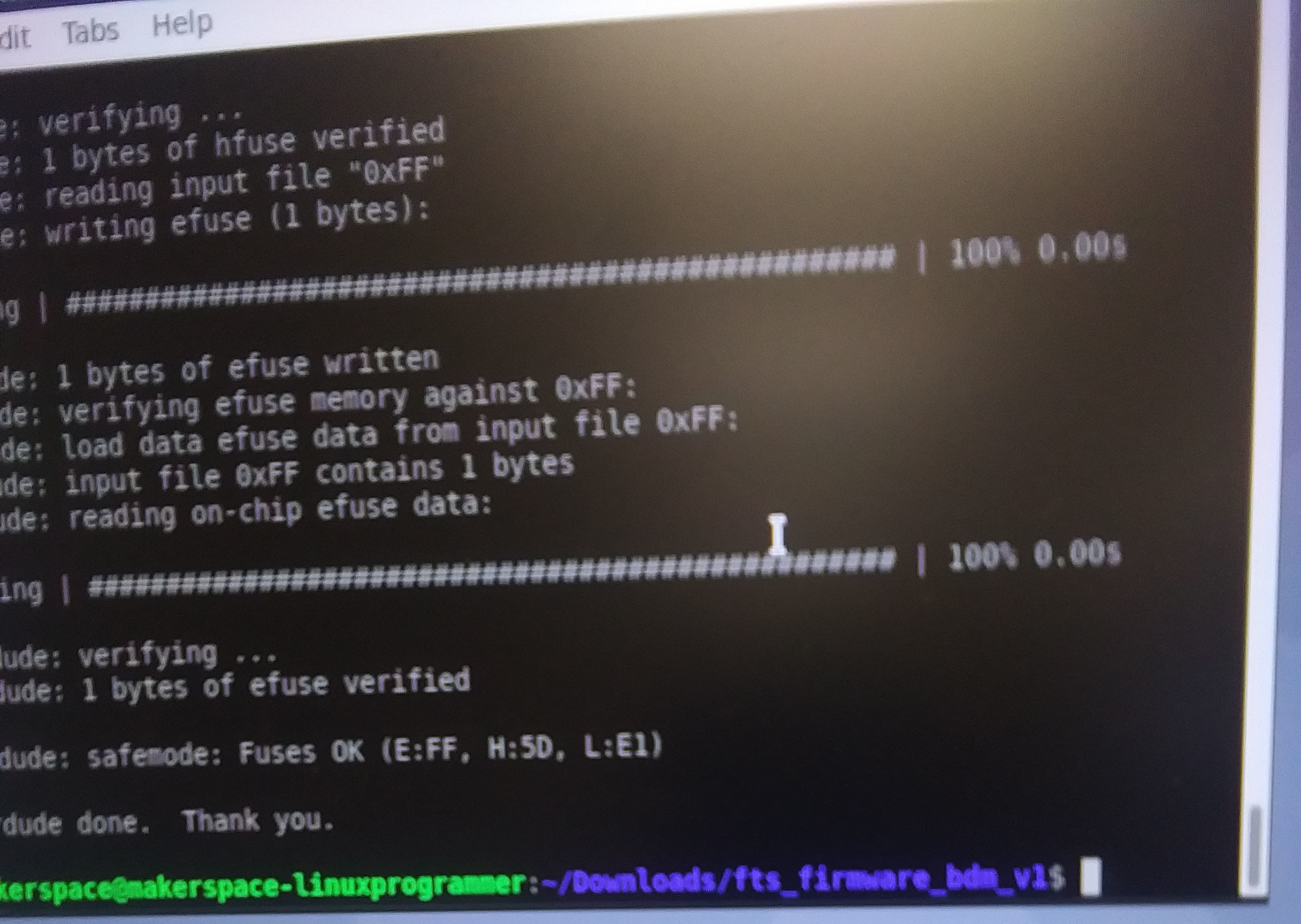
This meant that I could blow the reset fuse, so that my board can not be reprogrammed. I typed in rstdisbl (several different times actually, because I misread the "l" as a "1" and kept typing it in incorrectly). With that, I was ready to unsolder the jumper cable, finishing the process. With that, my FabTinyISP was complete!
Files
Circuit Board Trace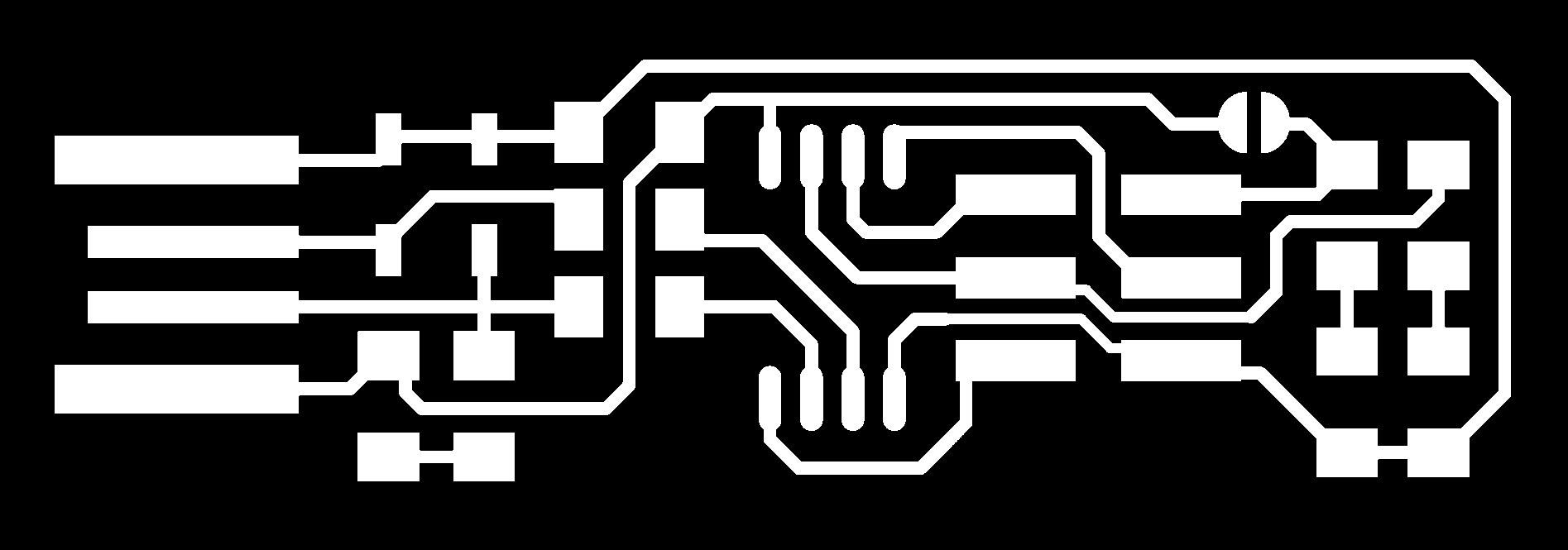
Electronics Map
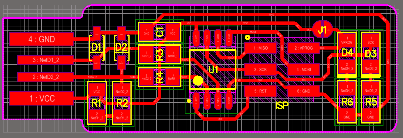