For the group assignment this week, we started by connecting a single custom board from a past project that utilized an LED.
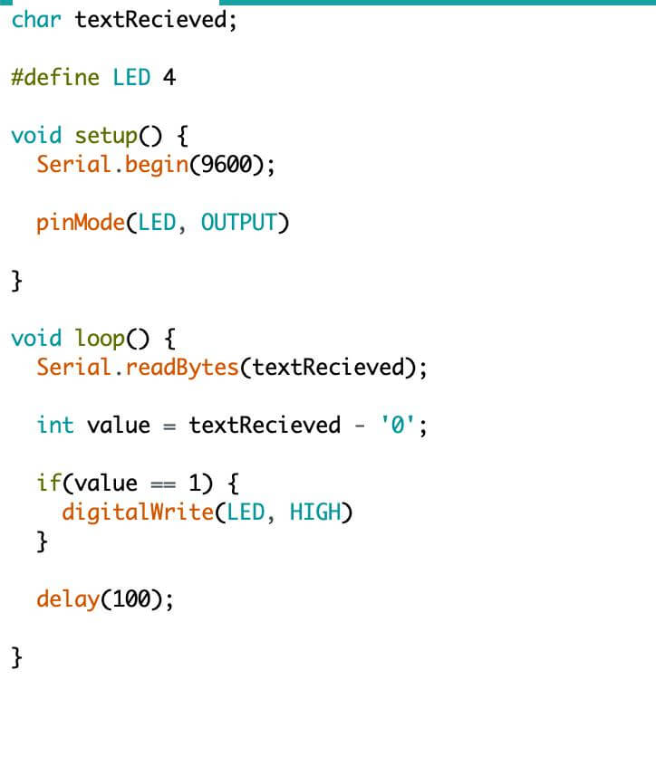
When the user enters any character in the Arduino IDE Serial Monitor, it would be sent to the custom board via serial. If the LED board receives a '0', it flashes the LED once. It does not flash for any other character it receives.
Here's a screenshot of the code we were running on the board.
Next, the two groups that were in the lab teamed up to have both of our board communicate with eachother. We had a board with a button and they had a board with a servo.
We were in charge of sending the signal to move the servo. We programed it such that it sent character whenever the button was pressed. The other group's board would recieve this character and move the servo a little bit each time until it reset. I think we allowed for 10 presses before resetting.
Now for the individual assignment...
I gotta be honest, this was a rough week and I struggled to stay motivated. I just feel like we have spent so many weeks on circuits and the process of milling boards that this week to felt extremely repetative and unnecessary.
And it is partly my fault for not milling a universal board that could be used for multiple weeks, but it was unclear how helpful doing so would be. This was my fifth or sixth time milling and soldering a board now and I'm just over it. The process of programming hasn't been any different and I personally believe this was the least informative and useful week thus far.
With that off my chest, let's see what I did for this week: Networking and Communications :)
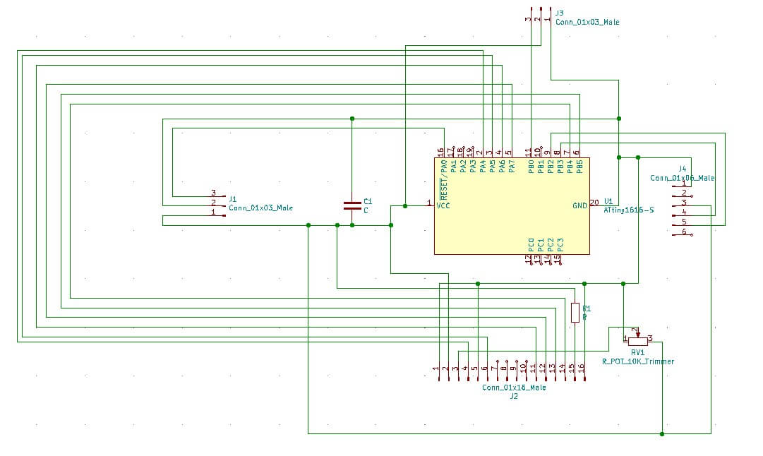
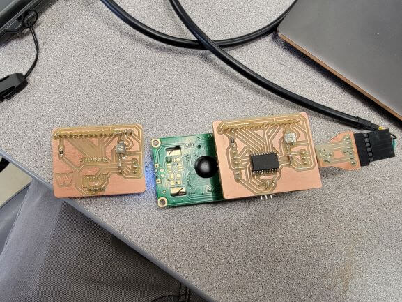
I modified my board from last week to include a 6-pin connector for the FTDI adapter so that I could easily connect to TX and RX to trigger the screen to display a message after a serial communication.
When a '0' is sent via the Serial Monitor, the Arduino passes it along to the LCD board via serial and the screen will display a message. But when a 1 is sent, the Arduino LED flashes 10 times, but the screen does nothing.
This is my version of a 'bus address' system.
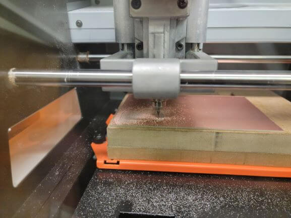
The process of milling and soldering the board was identical to my process last week with a few minor design differences which I will highlight below.
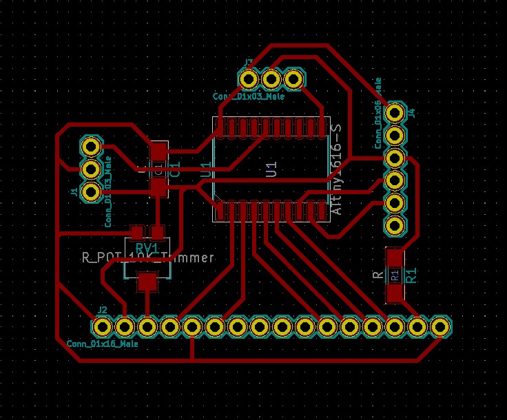
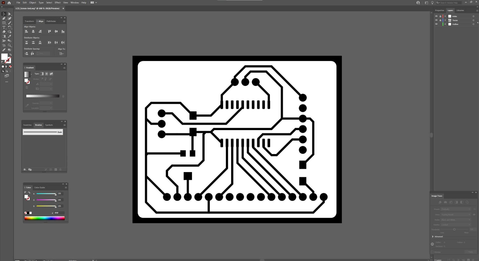
Here's the Illustrator file including traces, outline, and holes (not shown)
I had to reuse my ATtiny from last week's board because my lab ran out :(
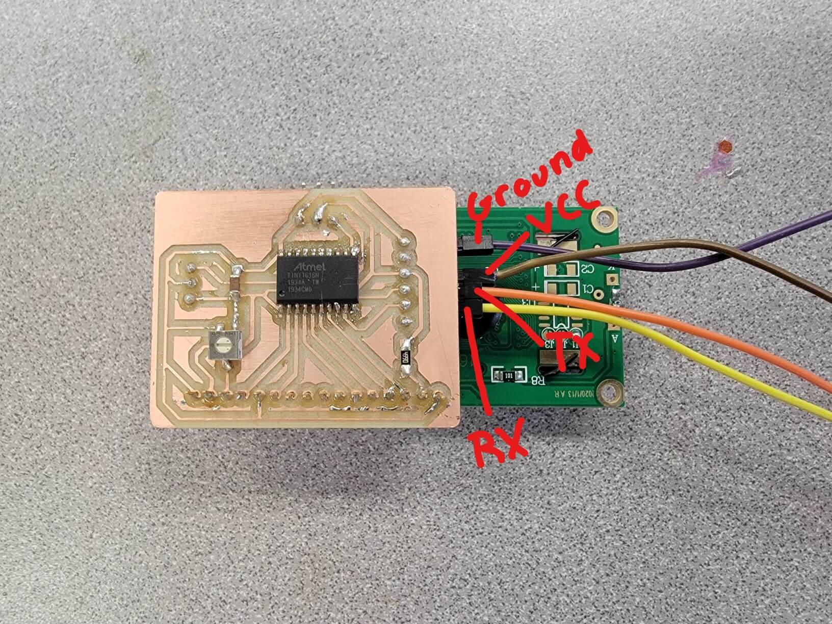
Here's the pin diagram of my FTDI connection
Ground goes to ground on the Arduino, VCC to 5 V on the Arduino, and then connect RX and TX to the opposite of themselves (RX -> TX and TX -> RX). The Arduino is then plugged in via USB and the values are entered in the Serial Monitor of Arduino IDE.