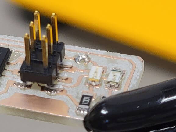
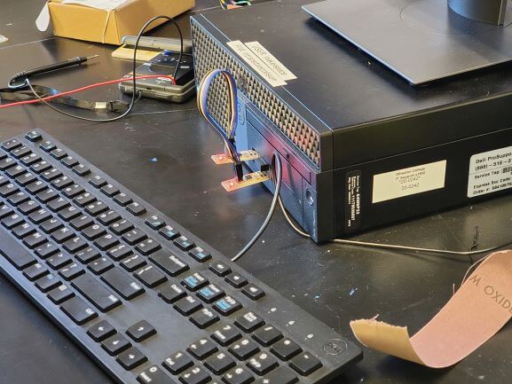
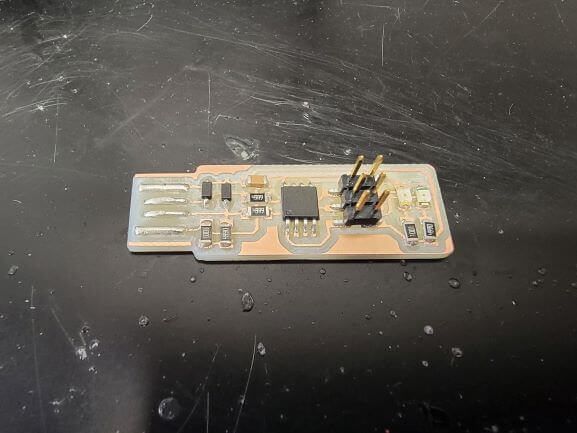
There was not a lot of work on the computer this week, so unfortunately, there is no fun timelapse. Here's a photo of my board after a bit on soldering instead!
Some Milling Definitions:
Feed Rate: the speed at which the cutter advances on the workpiece. Usually expressed in inches or millimeters per revolution.
Spindle Speed: the rotational frequency of the spindle of the machine. Expressed in revolutions per minute.
Plunge Rate: the speed at which the router bit is driven down into the material when starting a cut.
Depth of Cut: provides necessary depth of material that is required to remove by machining. Usually expressed in millimeters and is usually given by the third perpendicular direction (Z-Axis)
Most of these definitions on this page and the chart below were taken from here.
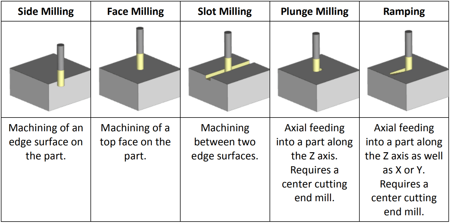
This is a great chart showing all the different types of cuts you can make using a milling machine.
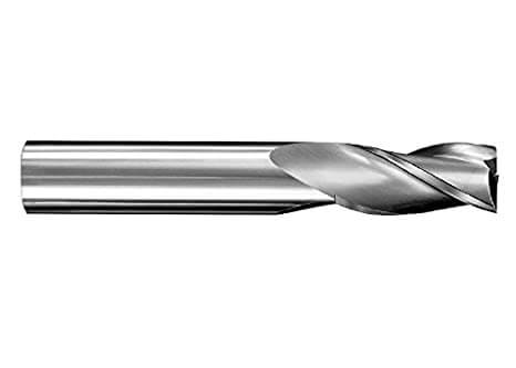
Square end mills are used for most general applications. Creates a sharp edge at the bottom of pockets or slots.
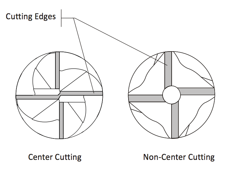
Square end mills can either be center cutting for plunge milling (left), or non-center cutting for side milling (right).
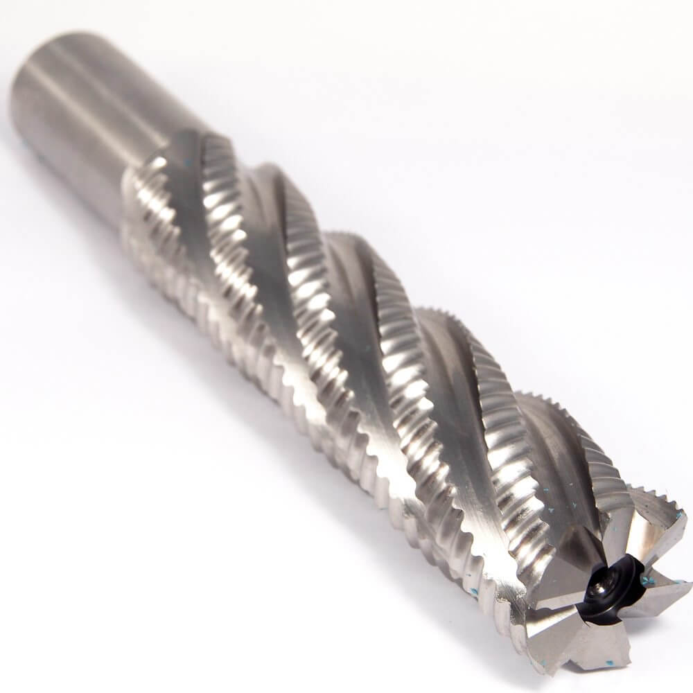
Roughing end mills have serrations in the teeth to remove large amounts of materials without much vibration.
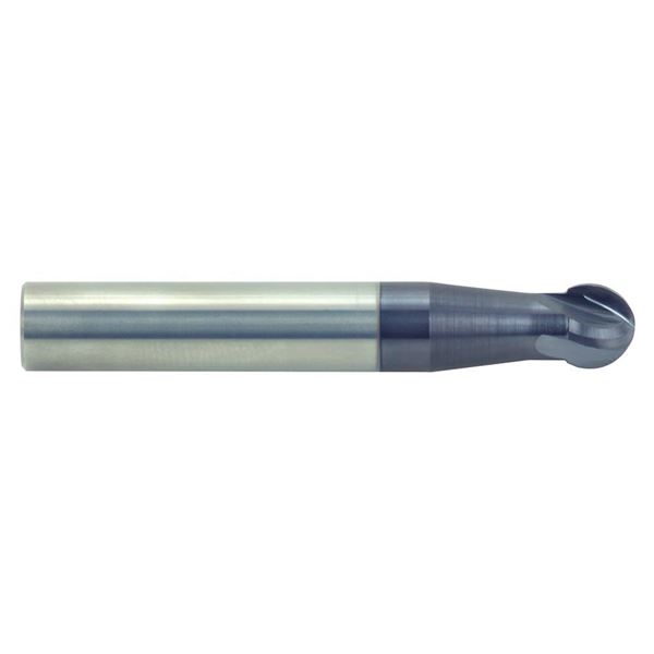
Ball end mills produce a radius at the bottom of pockets and slots. Used for contour milling, shallow slotting, and pocketing applications.
Flutes:
End mills have spiral-shaped cutting edges on their sides known as flutes that allow material to escape when the mill is in a slot or pocket.
End mills typically have 2, 3, or 4 flutes.
More flutes means more cutting edges but less room for material to escape.
The number of flutes on an end mill depends on your machine and the material being cut. More flutes cut harder materials faster, but may cause issues with spacing for material to escape.
End Mill Materials:
High Speed Steel (HSS): Provides good wear resistance and costs less than cobalt or carbide end mills. HSS is used for general purpose milling of both ferrous and nonferrous materials. While usually inexpensive, HSS does not offer the tool life or speed advantages of cobalt and carbide end mills.
Cobalt: Cobalt is an M42 tool steel with an 8% cobalt content. Cobalt is more expensive but provides better wear resistance and toughness than HSS (M7). Because the tool can run 10% faster than HSS, metal removal rates and finish are better than HSS.
Solid Carbide: Carbide is considerably harder, more rigid, and more wear resistant than HSS. However, carbide is brittle and tends to chip instead of wear. Carbide is used primarily in finishing applications.
End Mill Coatings:
Standard coatings include Titanium Nitride (TiN), Titanium Carbonitride (TiCN), and Aluminum Titanium Nitride (AlTiN).
Long-life TiN (titanium nitride): good for use on alloy steel, aluminum, and plastic. Color is gold.
Extra-life TiCN (titanium carbonitride): better wear resistance than TiN coating, making it a good choice for tough-to-machine materials such as ductile cast iron, stainless steel, aluminum, and plastic. Color is blue-gray.
Super-life AlTiN (aluminum titanium nitride): best for very high feeds/speeds and high-temperature applications. Used to mill cast iron, stainless steel, nickel-based alloys, and titanium. Not for use on aluminum. Color is purple-gray.
We first had to complete the group assignment. It started with the reseach above to ensure that we knew the basics behind milling.
We then grabbed the PNG files from Fab Academy for the line test.
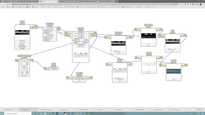
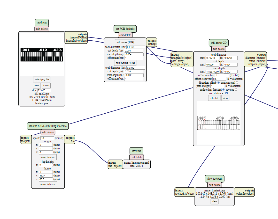
We then opened MODS and selected the server program for our Roland SRM-20. Then we uploaded the PNG.
We had to change the origin to be at (0, 0, 0), set the speed to 10, and load the server module to save the file rather than send it to the mill.
We repeated this process for the outline and set it to cut rather than trace.
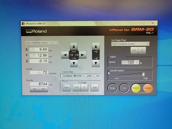
Next, it was time to load the first file (trace) into VPanel and set up the mill.
Setting up the mill involves using double-sided tape to hold down the fiberglass and copper sheet. Use VPanel to move the bit to the desired origin and set the X/Y origin. Install the bit and move it down the Z-axis until it is just above the material. Losen the bit clamp so the tip of the end mill falls against the copper. Tighten, set as Z origin, close the lid, and cut!
I apologize I do not have pictures of the above steps. I was so caught up in getting it right that I totally forgot to document!
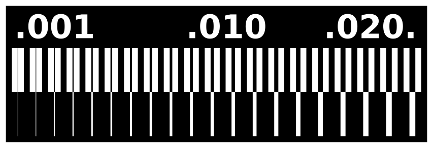
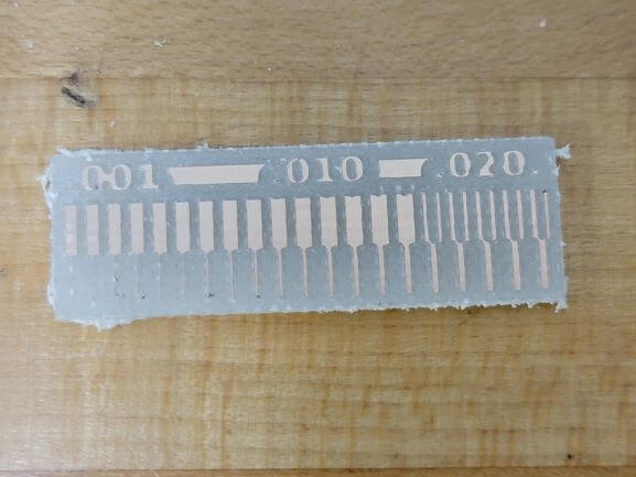
We used a 1/32" ball end mill to trace and a 1/32" flute end mill to cut the outline. This is what we ended up with.
As you can see, the mill does an incredible job with a 1/32" bit. It is able to trace the outer paths all the way down to .001, but cannot mill the interior grooves much narrower than .020.
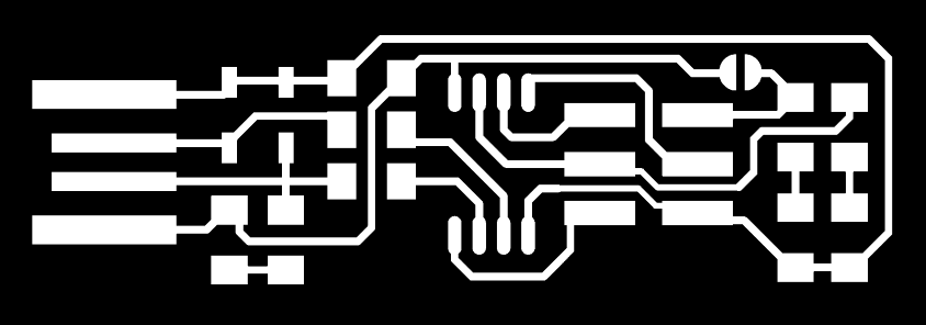
Now it was time to begin the individual assignment and build the FabTinyISP.
Getting the RML files and setting up the mill was exactly the same as in the group assignment except we have to use the correct trace and outline files directly from the Tutorials page.
Here's a video of the milling of the FabTinyISP trace.
And here's an extreme close up of the outline being cut.
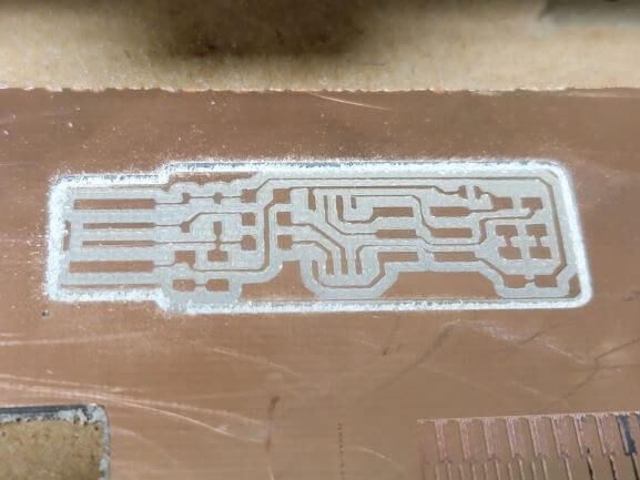
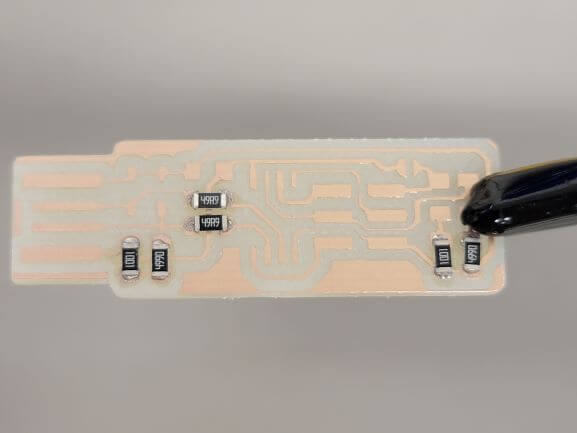
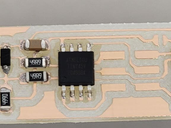
Once the board was milled, it looked like this. Time to solder!
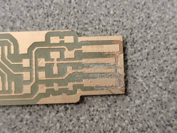
I quickly want to note that the above steps were for my second board. My first attempt was unsucessful as the copper plate was warped. This resulted in the grooves on the USB end not being fully milled.
The scratches are from me attempting to hand-mill with an X-Acto knife. Didn't work very well...That's why I decided to try a second attempt with a flatter piece of material.
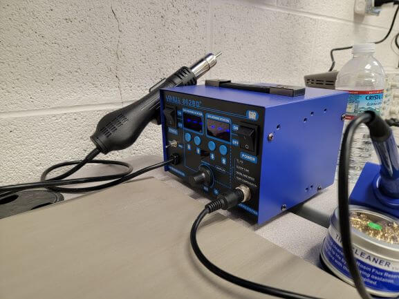
I soldered using the hot air side of the soldering station (left) in combination with liquid solder.
I had some experience with a soldering iron, so the air method was difficult at first. Now that I got the hang of it and realized you can turn down the airspeed, I definitely prefer air-soldering.
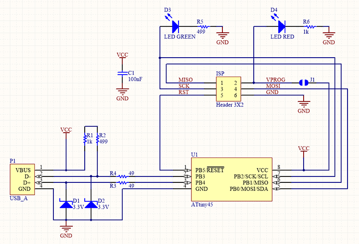
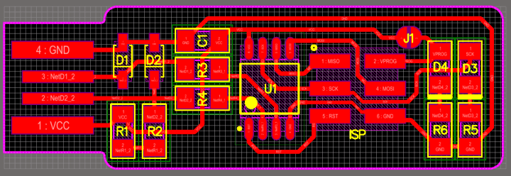
Here's the circuit diagram that shows all of the components and how they connect to each other.
Here's the diagram that shows the positioning for each component.
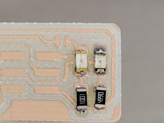
I started by soldering all of the resitors on.
Then I soldered the 2 LEDs. We were out of green LEDs in the lab, so I had to use an orange one instead.
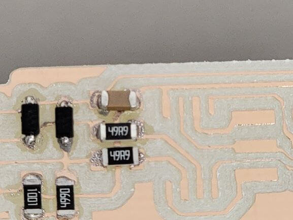
Next I soldered the 2 zener diodes and the capacitor.
Then the ATtiny 45.
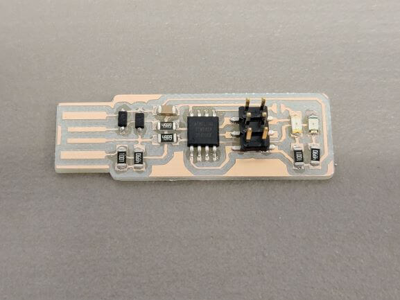
Finally, I soldered the 2x3 pin header onto the board.
That's all the components!
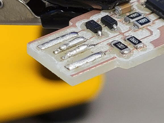
To make the USB side, I scraped the excess copper off and used a soldering iron to make the connections.
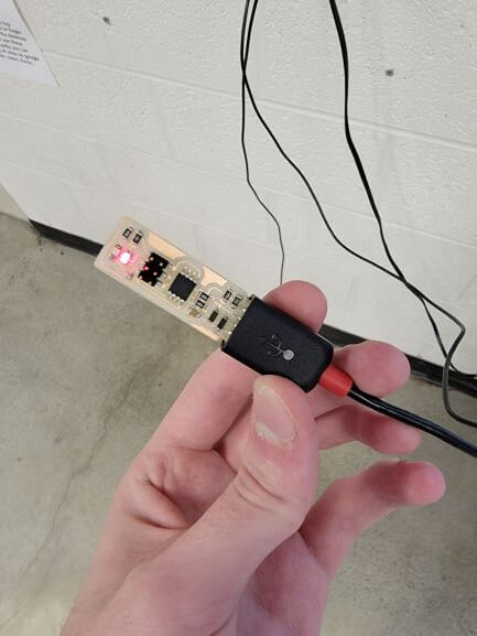
And when I plugged it into power, it lit up! Perfect!
The next step was to program the chip using the programmer.
This proved to be more difficult than expected for a variety of reasons.
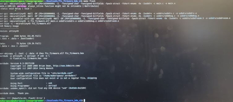
Here's the error message that kept coming up when I first tried making my programmer.
It's a little tough to see, but it says "Cannot find any USB devices" and then a string of digits. After some troubleshooting and discussions, our class determined that the USB devices were not enumerating properly. Linux wasn't picking anything up when the programmer or programmee were plugged into a USB port
Our TA worked some technical magic that allowed for our devices to register. I was then able to walk through the steps to make my board a programmer.
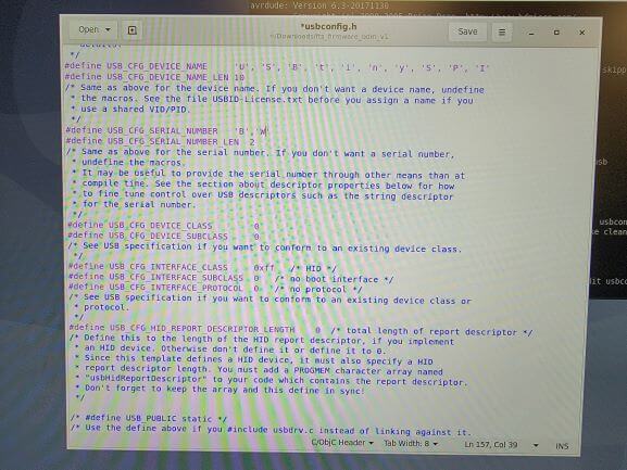
Here's me editing 'usbconfig.h' to add my initals as the device's unique serial number.
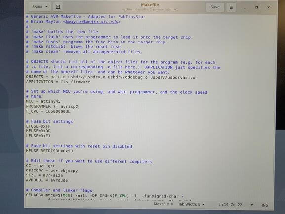
And here's what the Makefile looks like
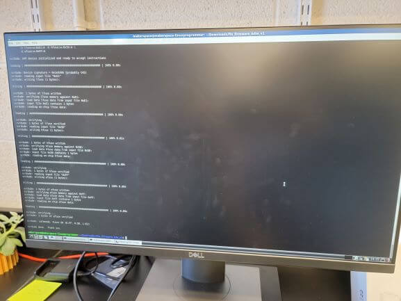
Here's what it looked like when my device was successfully programmed.
What an amazing screen to see!
And just like that, I had a working FabTinyISP programmer!
Unfortunately, I do not have photos of actually programming the fab ISP. As stated above the process involved editing 'usbconfig.h' to make it match my USB's name. Then, after plugging it into the computer and the already-working programmer, I ran 'make flash' in the Linux Terminal. Then, it was successfully programmed!
Unfortuantely, I think my shorted out briefly after programming it. So, it is no longer working to plug in and check the device manager. I do, however, remember that we knew everything was working because the computer made the audible USB Device Connected tone whenever I plugged my Fab ISP in. This should only happen when a valid USB device in plugged into a port. Also, it did not do this before Noah fixed the issue.