This timelapse shows my progress working on my design in Fusion 360. I chose Fusion as my primary environment for CAD since I have worked with it before. But believe me, I am no expert.
What this timelapse doesn't show is me looking up how to do simple things, like how to make non-circular holes...
But before I could begin modeling in Fusion, I had to sketch my design sice I have a new final project than before.
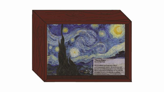
I am calling my new final project the smArtist Frame; an internet-connected frame that displays works from numerous small artists.
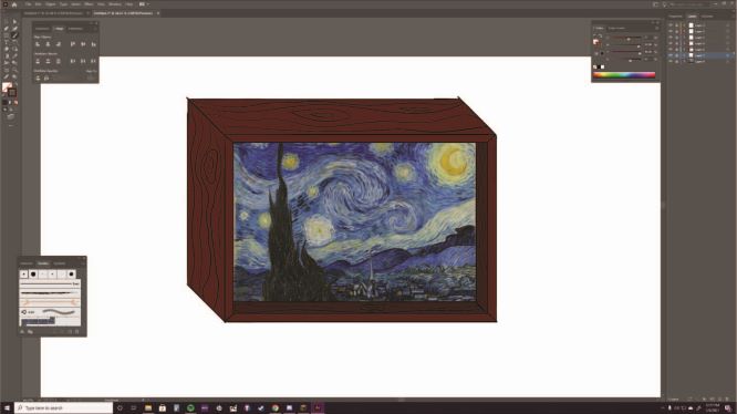
I decided to sketch in Adobe Illustrator because I have a small Wacom drawing pad and Illustrator allows me to make the most out of it.
To the left, you will see my completed sketch!
Read below to see how I made it!
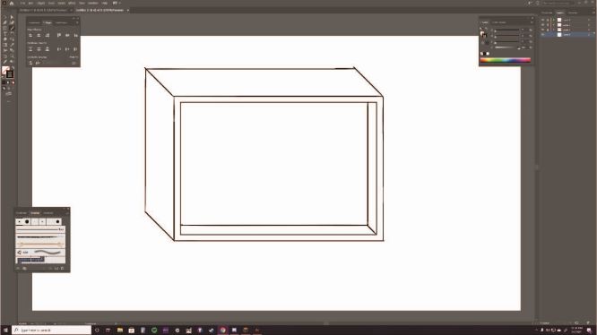
First, I started by sketching the frame. Did you know that even with a drawing tablet and brush tool, holding shift forces staight lines?
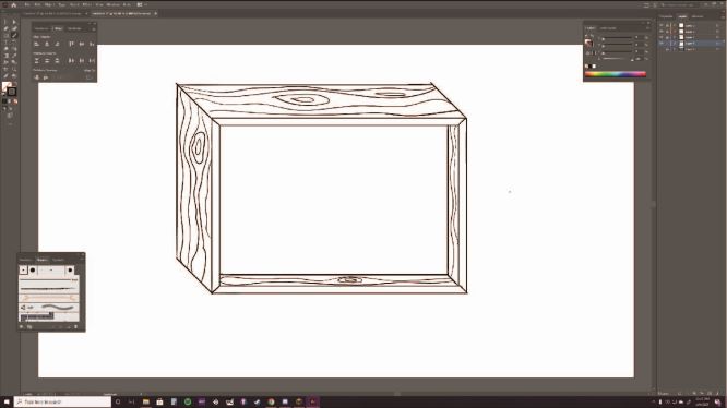
Then I drew on some wood grain. I really want the frame to be made of a nice quality wood. Mahogany, perhaps?
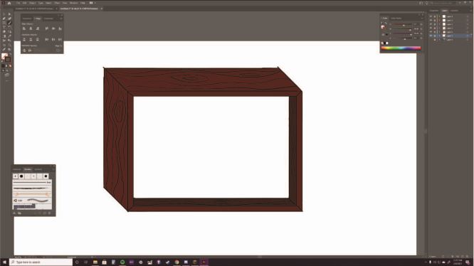
Then I added some color.
And I finished by adding an image of Vincent Van Gogh's "Starry Night" to better portray my idea.
Then it was time to begin modeling in Fusion 360!
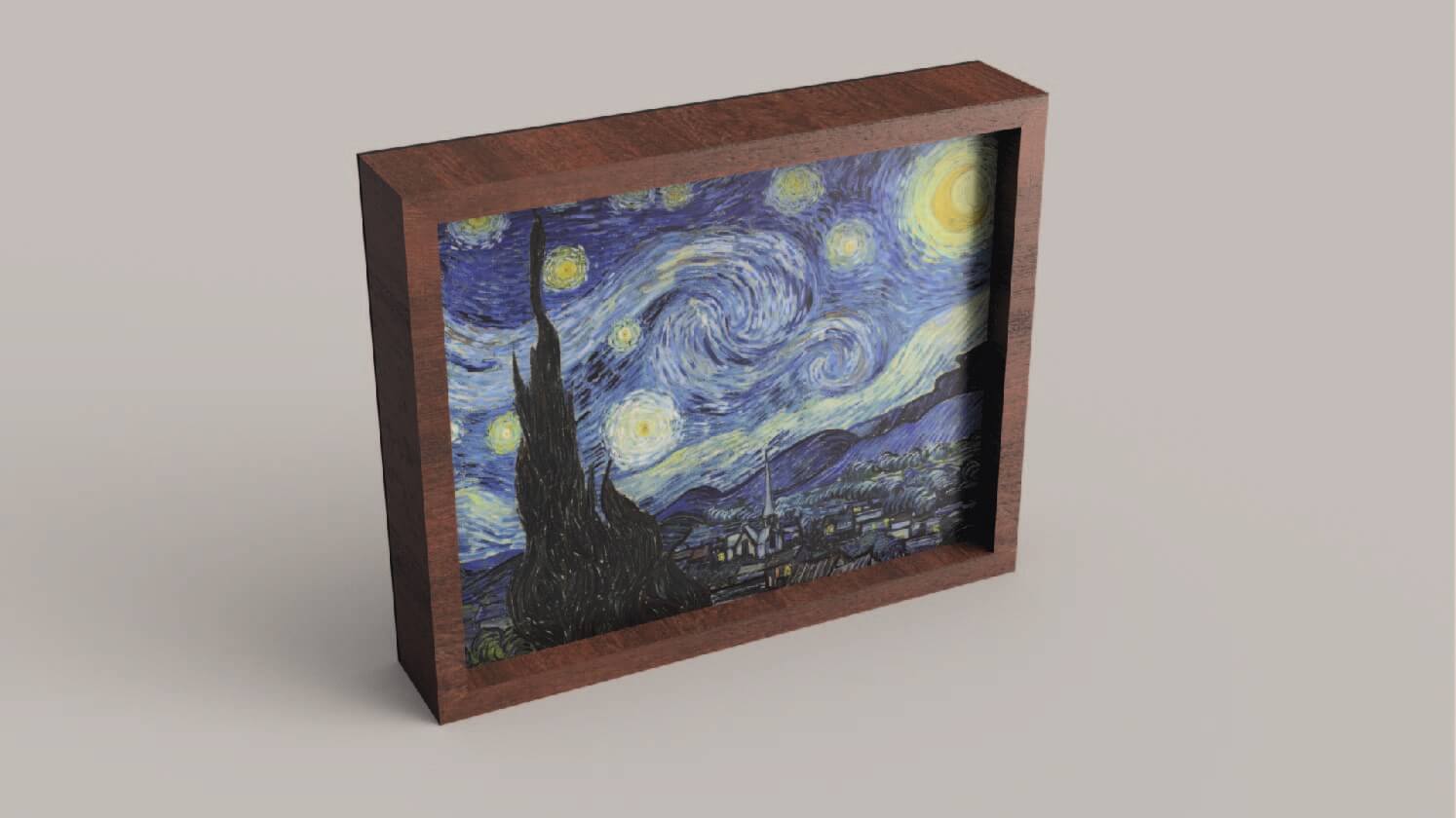
I learned a lot from my sketching, but most importantly, that the frame was way too thick. It looked like an old fashioned television in my drawings. I was aiming for a more sleek, minimalistic design.
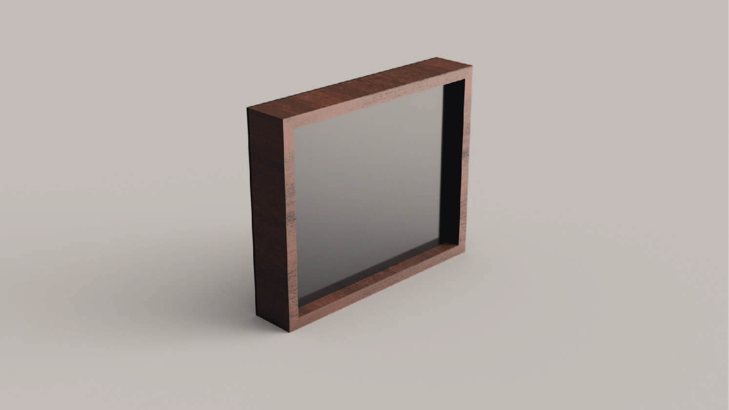
As you can see from the final rendering above, I think I successfully fixed this issue while modeling.
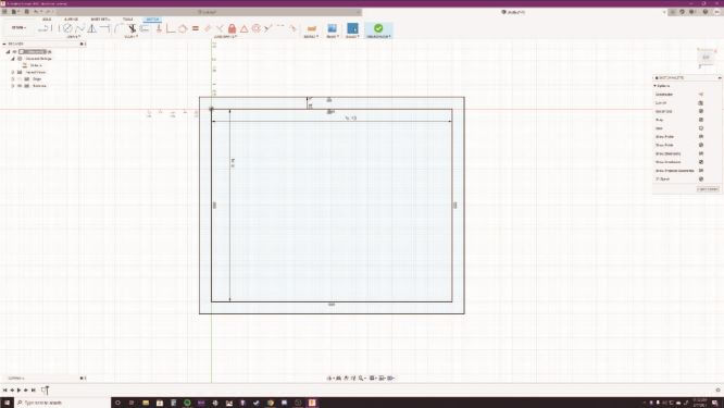
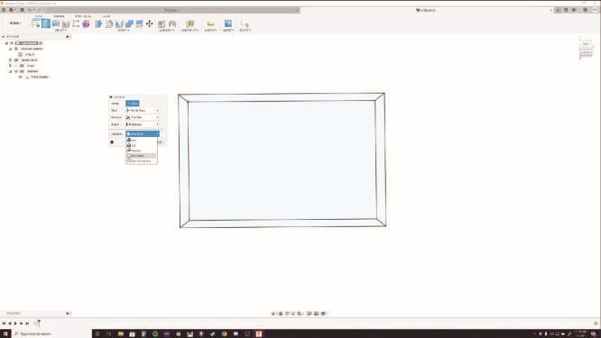
As with any design in Fusion, the first step is to start with a sketch.
I knew that I wanted the screen of my frame to be 8" x 10", so I started with that size rectangle so that I could build the frame off from that.
In this sketch, I created an offset of 1/2" for the thickness of my frame. This gave me a larger rectangle (the frame) containing a smaller rectangle (the screen).
I then connected the corresponding corners of each rectangle to simulate how the frame will be built using 4 pieces of wood.
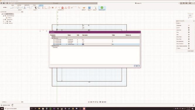
I used custom user parameters for each measurement to make changing dimensions easier
Here's the final sketch of the frame, now it's time to extrude
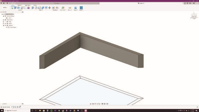
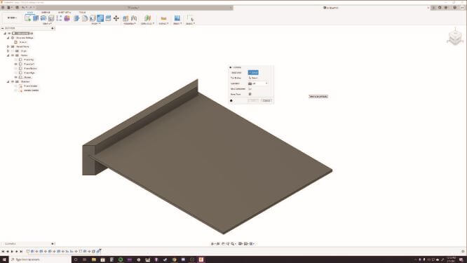
Extruding the sides is where I first ran into some difficulty.
When I would extrude 2 adjacent sides of the frame, they would combine into a singular body. I tried changing the extrusion setting with no luck.
In order to fix this, I extruded one side at a time and after each, I would use the move tool to move that new body up. This allowed me to make the frame out of 4 separate bodies.
I used the align tool to fix any corners that were misaligned
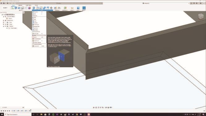
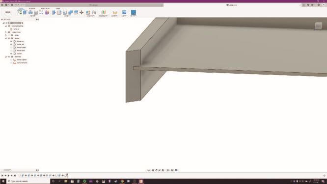
I then modeled a screen with an offset around all sides that overlaps into the frame
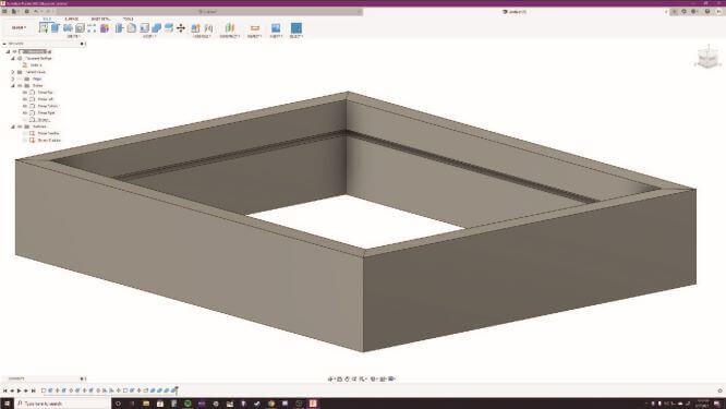
Using the combine tool in cut mode, I used the screen's overlap to cut a groove along the inside of each side of the frame
This created a groove along the interior of the frame to hold the screen in place
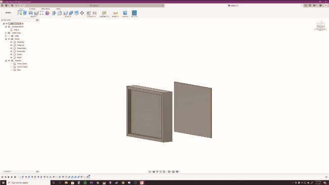
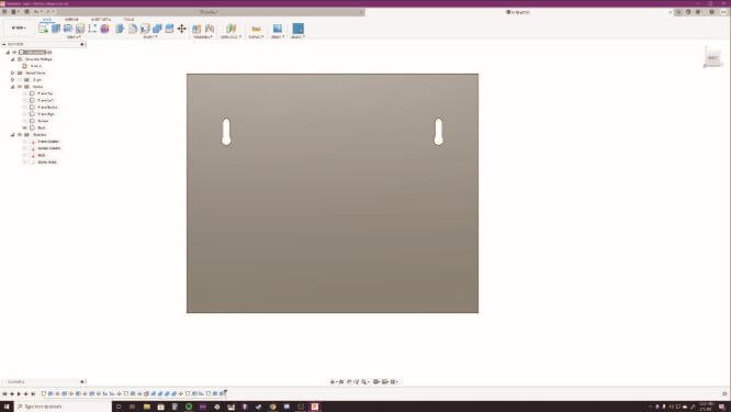
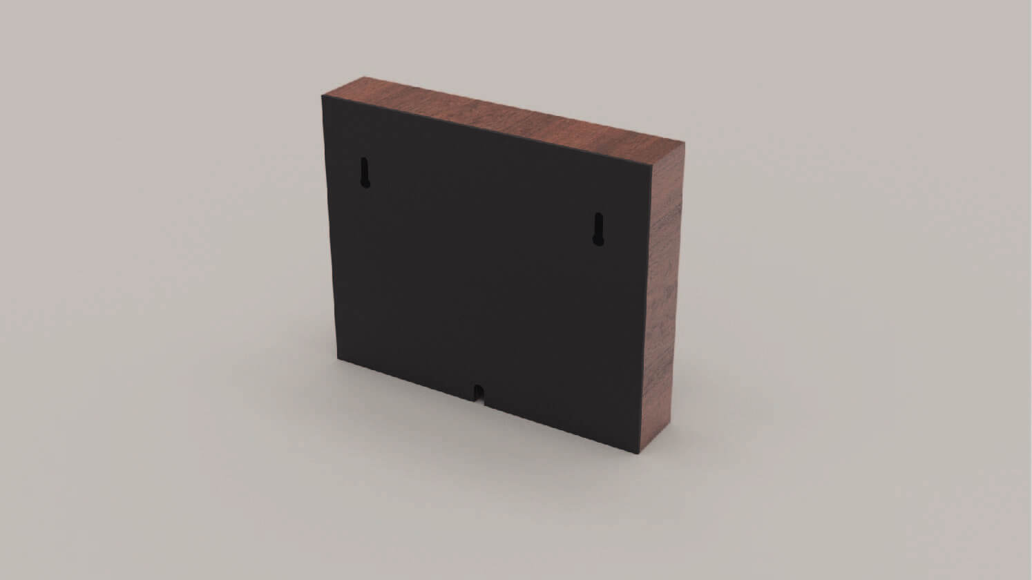
I created a 9" x 11" back panel to cover the open back
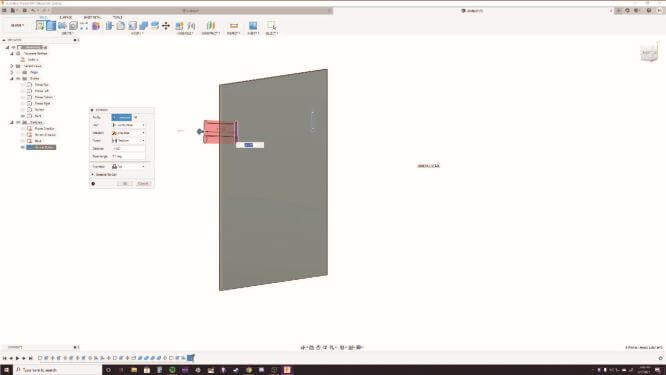
I then sketched screw holes on the back panel used the push/pull too to cut them out
Here's the back panel with the screw holes cut out
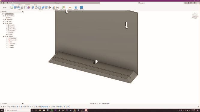
I also cut a hole on the bottom and back of the frame to run the power cable
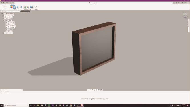
I used the appearance tool to change the materials before rendering.
The frame is made of semi-gloss mahogany, the back panel is semi-gloss black plastic, and the screen is glossy black plastic.
In order to download some of these materials, I had to restart Fusion to apply an update. Easy fix.
I then setup the scene, chose photobooth lighting for my environment, and used the in-canvas renderer.
A quick fun fact about Fusion's render feature: it once caused my computer to blue screen! This was actually super helpful
becuase it showed me that the overclock on my CPU was unstable.
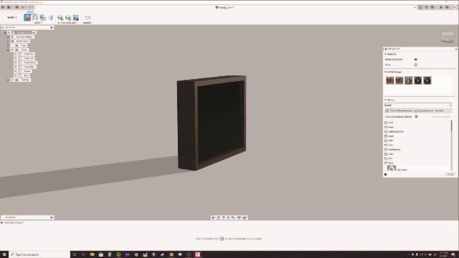
Anyways, check out the final render's below! I think they came out awesome!
Front (screen off)
Back
Fusion also has the ability to map an image to a face. So I used this to simulate the screen being on.
Now that I had created my model in Fusion, I wanted to experiment with a modeling software that I am not at all familiar with but had always wanted to learn; Blender.
I figured that I would create a component that utilizes the physics engine in Blender. So, I decided to model a hanging cable from my frame, which I imported as a .obj file.
All around, I thought that Blender was fairly difficult. It doesn't seem as intuative as Fusion 360, but the physics were awesome!
Here's the video I referenced on how to make wires with physics in Blender. It's a little outdated, but it's fast and offers the easiest solution I have found.
I modified his technique a little bit, as you will see below. I modeled the shape of my wires using the path tool rather than connecting two verticies as he does.
Also, my wire only had one endpoint, not two.
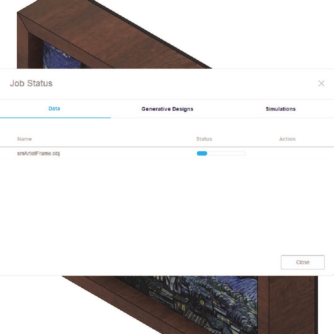
The first step was to export my frame as an object file (.obj) using Fusion 360.
I did this by clicking the top left drop down menu in Fusion and selecting export. Then name your file, chose a file type, and the location to export to.
The process to actually export the .obj file took about 3 minutes to complete.
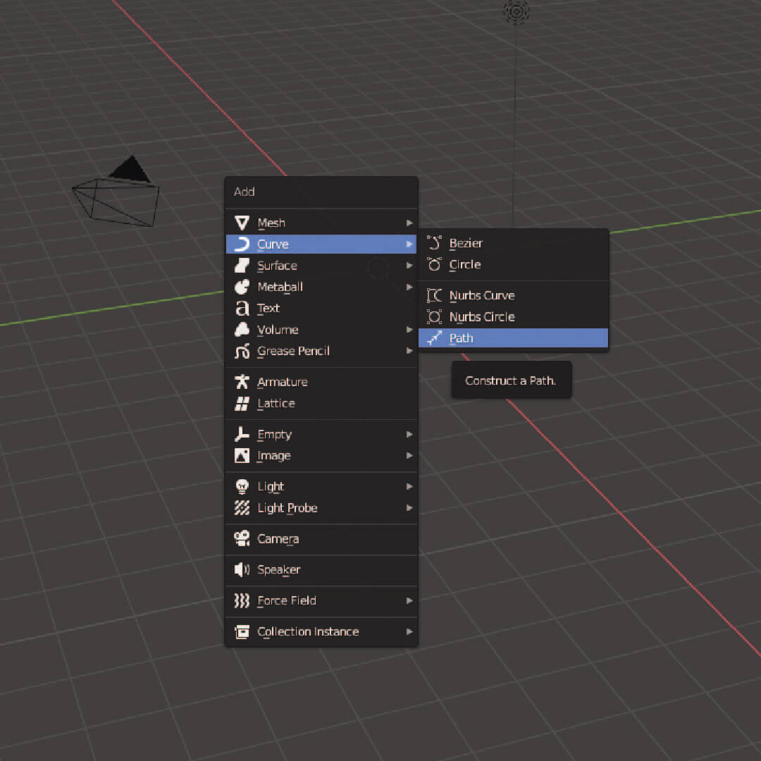
Now, the first step in Blender was to add a path for the wire to follow.
I did this by opening the add menu (SHIFT+A) and selecting Curve -> Path.
I then scaled this path to be a reasonable length for the power cable of my frame.
Next, I imported the oject file into Blender so that I could position the path.
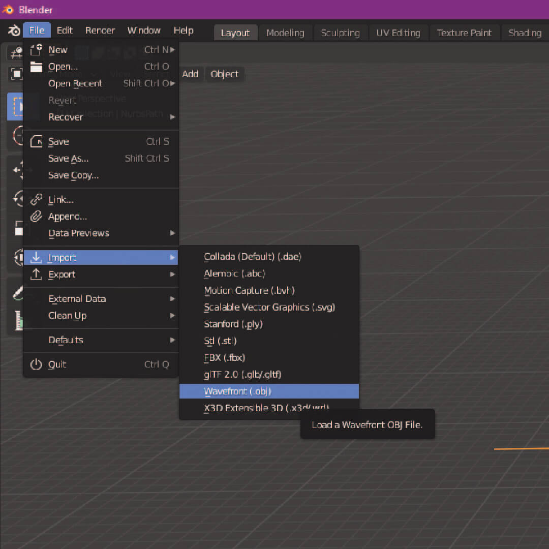
To do this, in Blender, select File -> Import -> Wavefront(.obj).
Then select your file, and it will magically appear in your Blender workspace!
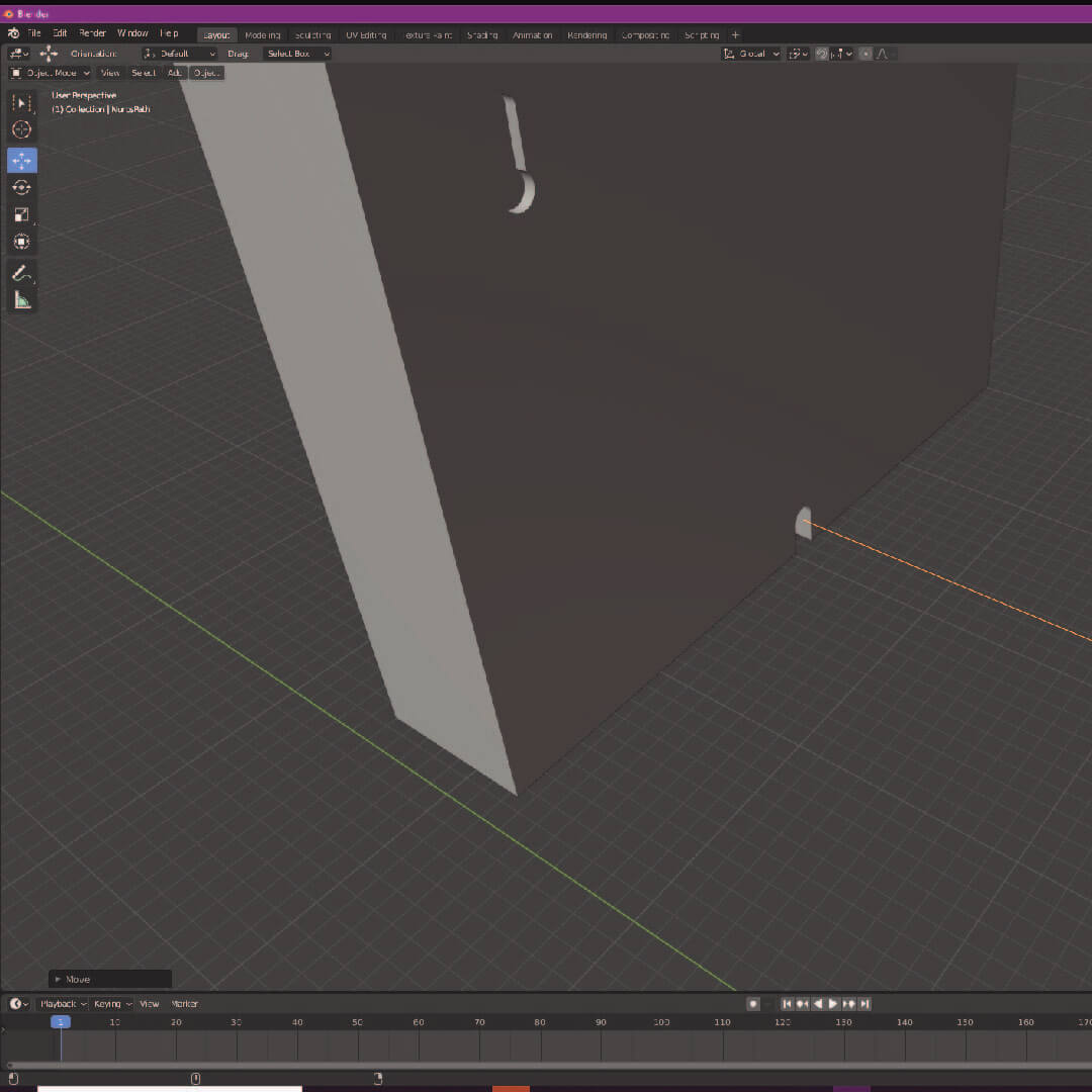
Use the Move Tool to line up one end of the path into the cable cutout.
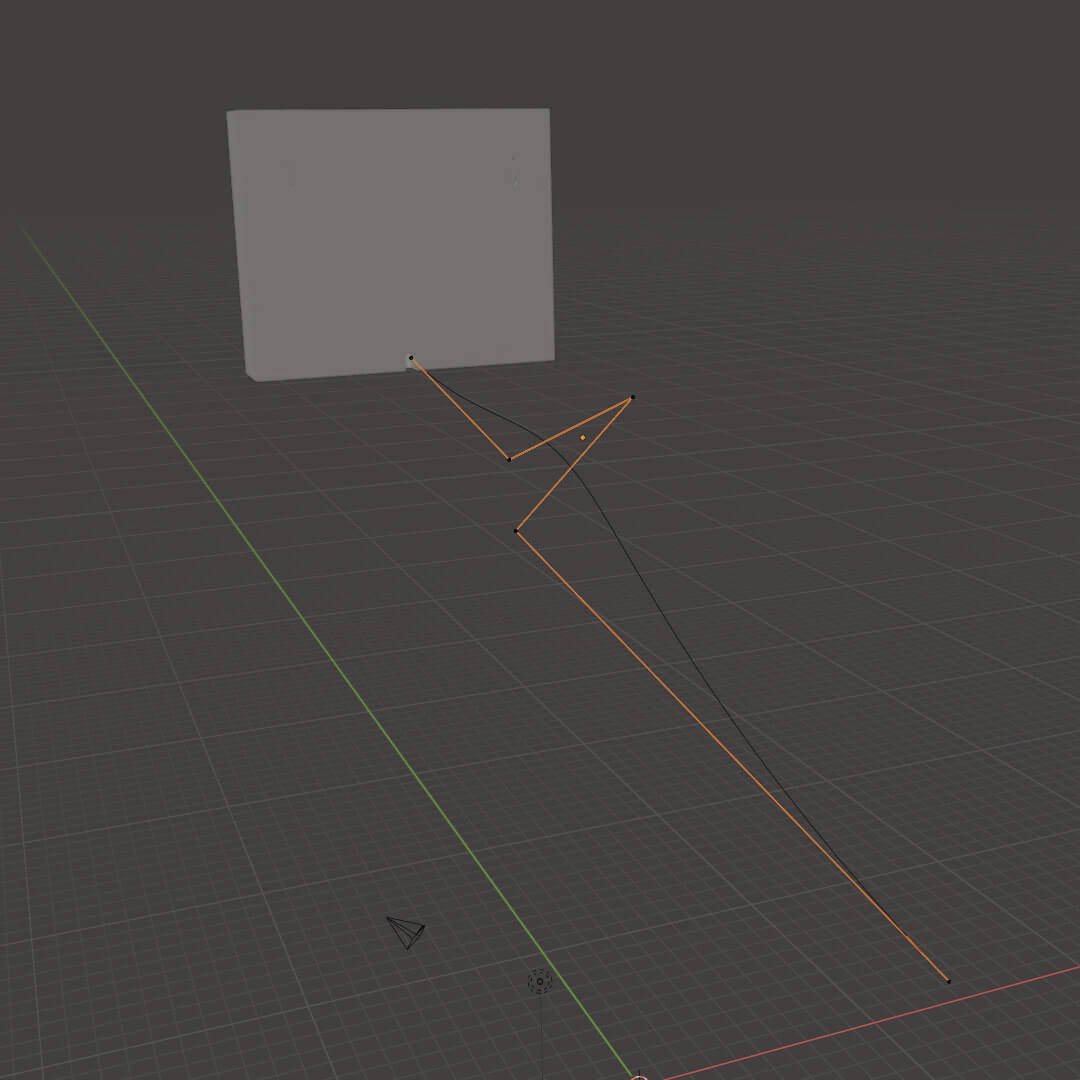
Then, in Edit mode, move various vericies on the path to make the curved cable.
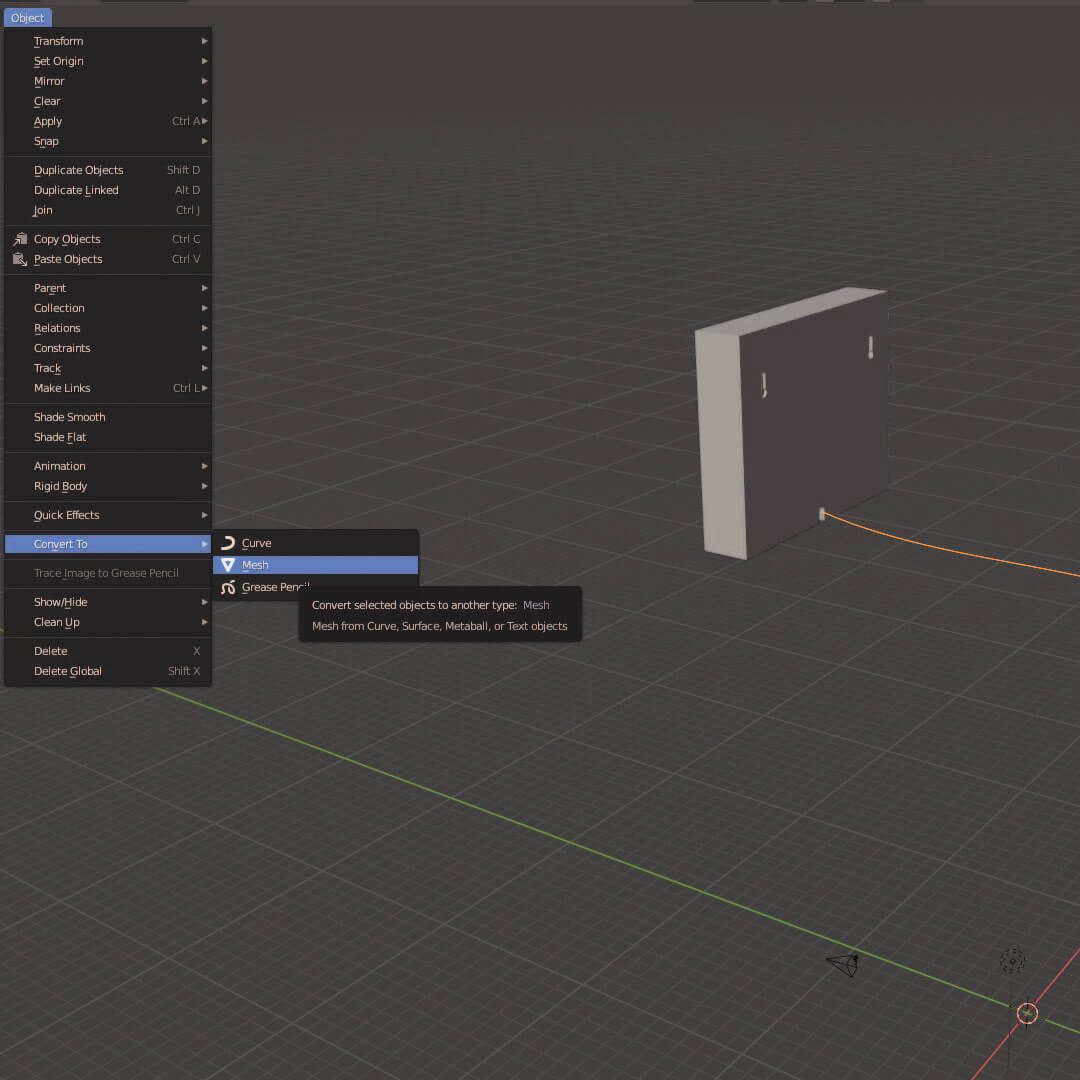
This next step is very important and something I had to figure out myself.
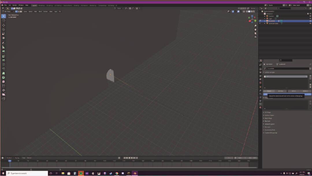
Select the path, select Object -> Convert To -> Mesh. This adds many more verticies to your path which are needed for proper physics.
Then select the end vertex that is inside of the frame and create a Vertex Group. I just named mine "Pin" since this is the point at which
the wire is pinned.
Make sure to hit Attach to add the selected vertex to the group.
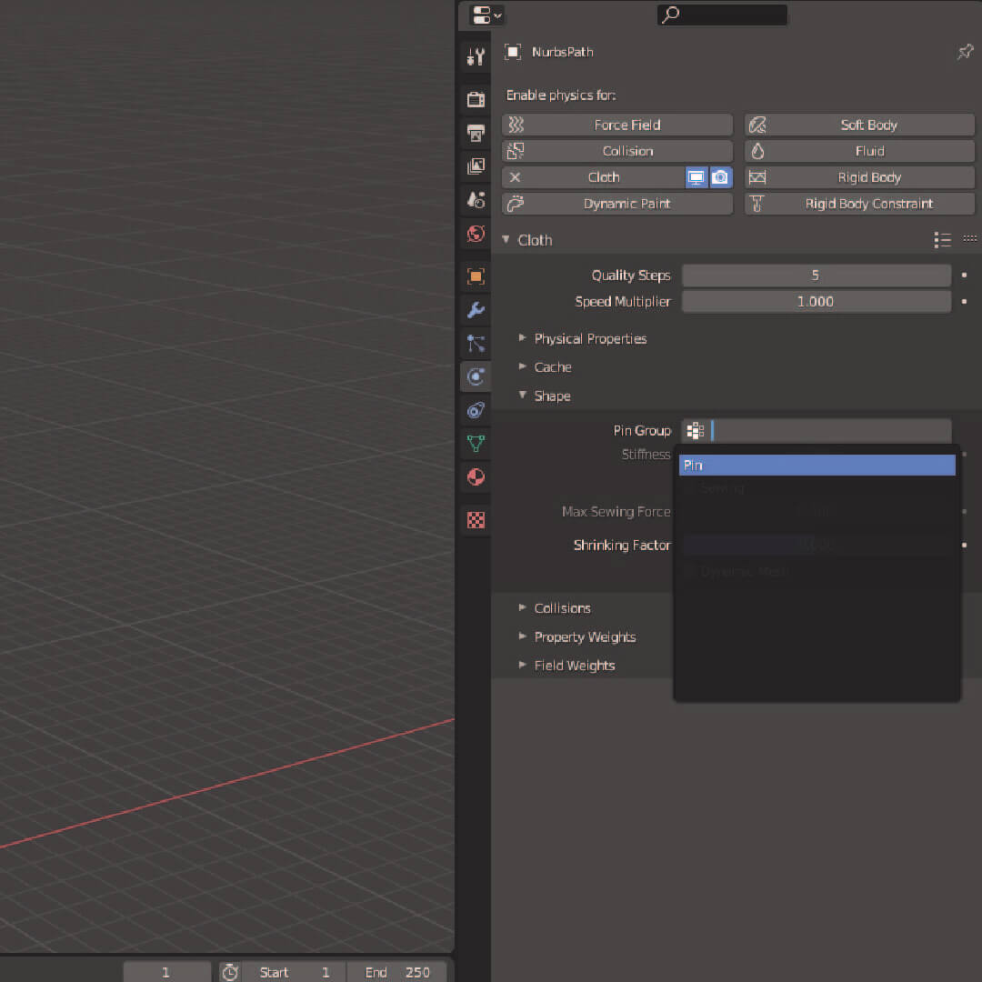
Then I applied Cloth Physics to my path. I had to pin the Vertex Group from the previous step in the Physics settings.
I also had to mess around with the Speed Modifier of the Physics to make the fall look more like a wire and less like cloth.
Here are the physics applied to the basic path. It still looks a bit too slow, but not too bad for my first Blender project!
And finally, I added a Skin Modifier to the path and ajusted the width to look proportionate to the frame.
I found that if I made the radius of the skin too large, the physics would really warp the shape.
Here are the physics with the skin added. Also, I added the sound for dramatic effect.