
Summary
Finally a board that I’ve managed to design and make work! (still working as I right this). It’s been tough going, with the circuit not being finished until you are satisfied that the programming of the board is complete.
What I thought I knew before
Everything I’ve been able to learn and absorb from the other electronics assignments.
Learning Outcomes
Theory and use of things i learnt from this assignment:
Demonstrate workflows used in controlling an output device(s) with MCU board you have designed.
Lessons to take away
-
Test each complex component on the board as you solder it to the board.
-
Systematically check each part of the circuit route and its connections to the computer if there are problems.
Group Assignment

- Measure the power consumption of an output device.
- Document your work (in a group or individually).
Power is the amount of energy transferred or converted per unit time. The unit of power is the watt, equal to one joule per second. Power is the rate with respect to time at which work is done; it is the time derivative of work:
where P is power, W is work, and t is time.
One Watt is the rate at which electrical work is performed when a current of one ampere (A) flows across an electrical potential difference of one volt (V), meaning the watt is equivalent to the volt-ampere.

Two additional unit conversions for watt can be found using the above equation and Ohm’s law.
where ohm is the unit of electrical resistance.
What we did

To start to measure the power usage of components, we connected a (analogue) power bank to a Arduino Leonardo (with servo program) to a servo.
-
Power bank (analogue)
This could deliver a steady voltage of between 0 and 20v, or a steady current of 0 to 2A.
We measured the Arduino board and found only 4v coming out of Arduino board to power the servo. Increasing the voltage to 7.5v into board, the voltage coming out for the servo was 5v. This mean we could safely assume there was a voltage regulator in between the V in and V out to the servo, which was taking some voltage to work itself.
We slowly started to restrict the amount of voltage coming from the power bank, to a point where the Arduino board just failed to deliver 5v to the servo. The difference between the voltage delivered by the power bank, and the 5v delivered to the servo is the amount of voltage that the regulator (and the board) needs itself.
Interesting we tried to compare the voltage signal for the servo when powered by the USB port of a laptop and then the power bank. The voltage was more stable from the power bank, and we could see lots of noise from the laptop battery/board.

We also decided to measure amps using the power bank meters. We found the servo takes more than 5mA, which was the maximum that the laptop USB specifications could provide could provide.
Using the oscilloscope we also read there was a large voltage spike/drop when the servo is sent a signal to move. The servo had a sort of current inertia that the servo’s magnets needed to generate to create a higher magnetic field to overcome it’s magnetic field’s resting state.
Measuring a separate voltage regulator with a multimeter: V in, GND, V out.
It turns out the regulator is very inefficient, it needs 1+ volts to work. So threshold V in from power bank is 1+v over V out of the regulator. Any voltage supplied above that threshold is dissipated as heat, which is why it has a fixing to attach to a heat fin.
Measuring unknown toy motor
Lucia brought in some old toy motors to play around with and measure. So we slowly raised the voltage from 0 on the power bank. 3v were needed to start to move the motor. With a steady 5v added, 4.14v was measured at the motor. We flicked a switch on power bank to change the mode of delivery to Amps. This was an easy way of measuring the amount of current, and we knew that voltage was 5v. Volts * Amps = Watts (Power!)
Interesting thing I learned about the digital multimeters, was that the connections on the left side for the probes has a known value resistor inside. This dissipates heat allowing higher currents to be measured. It has a lower value resistor in parallel with the voltage meter. The multimeter then measures the voltage drop across the resistor to work out the Amps. V=I*R (R is too small to make a difference).
Mistakes & Issues
Oscilloscope measured 45v coming out of the power bank This didn’t match with the ~5v coming our of the power bank. AFter much checking of the settings on the oscillocsope we found someone had enabled the ‘x 10’ button so the signal on screen of oscilloscope was reading 10 times that of what was coming in. So it looked like 45v coming out of the power bank. To double check we measured the output of the power bank with a digital voltmeter - 5v!
Servos All the servos we tried to use to measure were all faulty or not working at all. So we didn’t see much signal of them working on the oscilloscope.
Individual Assignment

- Add an output device to a microcontroller board you’ve designed and program it to do something.
Concept
The idea was to continue with the board i made for the Input week with an RGB LED output. Since that was some what of a failure, there was some serious improvements to be made. As this combination of a 3 axis accelerometer coupled with a RGB LED it was imperative that i could develop this further. See the updates to Week 10.
As i tried to redesign the board with a RGB LED and the corrections to make the the board work, I realised that there was some serious programming going to be needed to get a reasonable output. Further research into the sensor revelaed that it ‘speaks’ to the IC in I2c or SPI protocols. Something I was advised not to go near until the ‘Communications week’. Taking that into account, I needed to come up with a board to complete the assignment. So I came to the conclusion that i could still create a board with an RGB LED, on a larger IC (ATtiny1614). Basically the same board I made before, but without the sensor. Because the RGB LED used separate input pins for each of the colours, I would need to upgrade the original ATiny412 I had previously used, i would have to use a ATtiny1614 with more pins.
At a later point, I would be able to combine the sensor and the RGB LED to a ATtiny1614 on the same board and program the IC with my future knowledge of SPI and I2C.
So with this new direction, I designed a board with an RGB LEd, as well as some separate coloured LEDs to use up some of the extra input pins on the ATtiny1614. Different from the input board, I added a button to add a simple input to the board instead of the sensor, and a serial output for debugging (missing in the input board).
This would be the basis (minus the 3 axis sensor) of a ‘development board’ for my final project that I could use to develop and debug the system, before making a final ‘production board’ version. I would design it in such a way as to allow the easy removal of components like the serial header pins and associated tracks for debugging that wouldn’t be needed on the ‘production board’ once it had been developed.
What I did
First of all was to search for the relevant circuits that i could use as a starting point for my board.
 .
.
Design criteria
This will closely match as possible the perceived design criteria for my final project.
- Small form factor. The final project is intended to fit on the wrist as a ‘wearable’ piece of technology.
- Powered by a button battery or ‘rechargeable battery unit’. (3.3v-5v?)
- Include a RGB LED. Whose hue, saturation and luminescence will be dictated by the 3 axis accelerometer in the future.
With an eye on the future spirals a little thought should go into including the following list of criteria into the design.
- The RGB LED part of the circuit should easily transpose to another circuit.
- The FTDI connection should be placed in such a way that it can be easily removed from the circuit schematic without the need for too much re-routing of the traces.
Initial decisions
The board would be designed around the ATtiny1614 for the extra pins, so it can handle the future sensor and the 3 inputs needed for the RGB LED alone. The FTDI will be placed in a position that can easily be removed when there is no need to debug.
To use up some of the extra pins (due to no sensor) I will add some extra single LEDs. As well as a replacement button as an input source to trigger the output response of the board.
BOM
| COMPONENT | DESCRIPTION | DATA SHEET | SPECIFICATIONS |
|---|---|---|---|
| 3 UPDI Header pins | To allow board programming/UPDI communication. Plus power 5v | Non-polarity. | |
| ATtiny1614 | More pins and memory than the ATtiny412. | ATtiny1614-16-17-DataSheet-DS40002204A.pdf | Polarity |
| Voltage regulator | To drop the input voltage by 1.2v (to 3.3v) for the sensor. | LM3480_datasheet.pdf | Polarity |
| Capacitor (1µF) | To stabilize power signal. | Non-polarity | |
| Resistor (0 Ohm) x2 | To use as a bridge for tracks to run underneath. | Non-polarity. | |
| Resistor (4.9k Ohm) x3 | To control amount of current going to the separate LEDs | Non-polarity. | |
| Resistor (1k Ohm) x2 | To control amount of current going to the Red + Green of the RGB LED | Non-polarity. | Non-polarity. |
| Resistor (499 Ohm) | To control amount of current going to the Blue of the RGB LED | Non-polarity. | |
| Button B3 SN | Input source. | Non-polarity. | |
| FTDI header pins | To allow serial communication. | Non-polarity. | |
| RGB LED, CLV1A-FKB | RGB colour combinations. | RGB-LED-datasheet.pdf | Polarity |
KiCAD

- Set up project.
- Open ‘schematic layout editor’.

- Place ‘Symbols’.
- Attach ‘Global labels’.
- Place direct connections with ‘Wire’s if needed.
- Place ‘no connection’ where needed (to stop errors).
- Place ‘PWR FLAG’s to suppress power errors.
- Run ‘Electrical Rules Check’.
- Run ‘Assign PCB footprints to schematic symbols’.
- Run ‘PcbNew to layout printed circuit board’.

- Set design rules with ‘Board Setup’.
- Track ‘Routes’ and manipulate components rotation/position.
- Run ‘Perform design rules check’.
- Draw outline of board with ‘graphic polygon’ tool, on ‘Edges cut’ Layer.
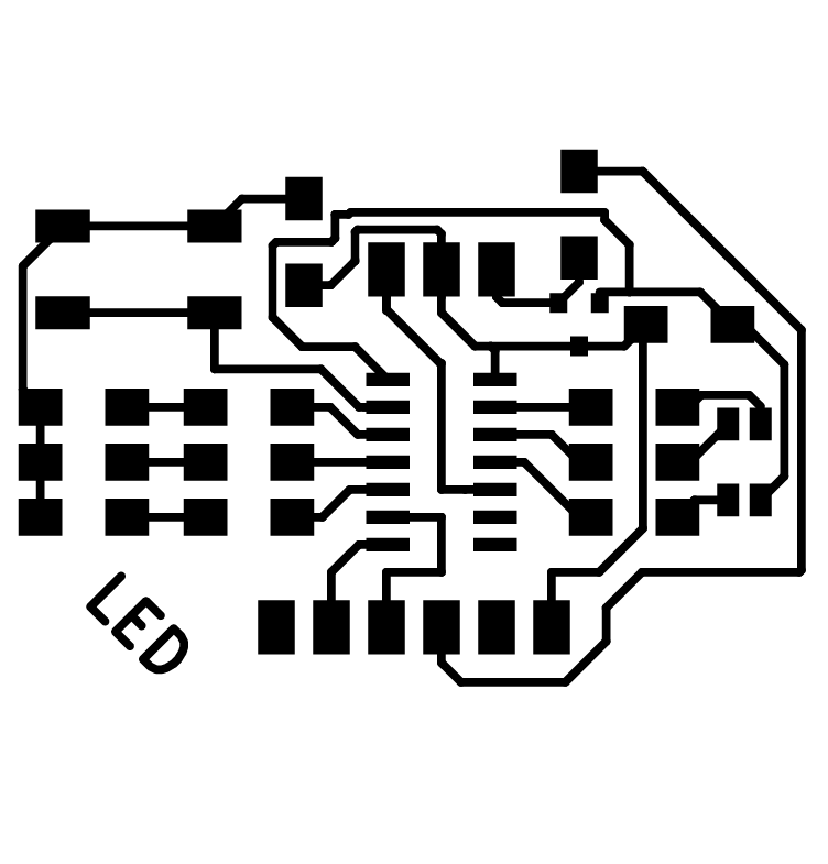
- Export ‘.svg’, for the traces layer (‘F.Cu’) and interior layer (‘Edges cut’).
What i think the circuit does.
Power and GND comes in from two of the UPDI header pins, or from the FTDI header, depending if I’m uploading programs or debugging with the serial communication.The VCC drops from 5v by approx. 1.2v in the voltage regulator to 3.3v. The power signal is then ‘smoothed’ by the capacitor.
3.3v is feed to the ATtiny1614 and the common anode of the RGB LED. This means, that the RGB LED will be activated with a LOW signal (thanks Erwin for that nugget of knowledge), and the separate LEDs activated by a HIGH signal from the ATtiny1614.
The button will be the input to start the program uploaded to the IC.
Board Production
This went surprisingly well considering my history with the small milling machine. The traces looked nice and neat. And not much space was wasted on this small board. But of course there was a problem - the edge cuts were too wide, and cut one track.
Soldering the board
As usual, positioning these small components with small connection points was the most difficult. Tinning these and the pads where they would go with the minimum amount of solder was important. Flux was my friend here, as it ensured that the small amount of solder on both surfaces was enough to make a firm connection.
Board Testing

As explained below in the Issues and Mistakes, the continuity testing gave the impression that this board’s production had gone very well. Until the ultimate test of trying to upload a program to the IC. When this didn’t work straight away, the various error messages weren’t helpful, as there was no results from the internet search engine.
I then had to take a step backwards and test from there. The problem could’ve been anywhere from the UPDI, wires connecting it to the board, and of course the board itself with all the components on it.
With varying errors and unrepeatable results, I spent many hours beating my head against the proverbial brick wall trying to find out what was wrong, and where.
Isolating and testing each individual element up to the board, as the most obvious error was a UPDI connection problem. The board’s UPDI connection was connected fine so i didn’t think the problem was there.
Eventually it came down to the realisation that the ATTiny1614 was bad. An internal connection (see below) between pins 7 and 14 made during the manufacture. But it doesn’t stop there. Hoping that this would solve all the errors when plugged in and a program uploaded, I was somewhat disappointed when the same and other errors popped up instead.
So began the querying of all the components on the board. And even the soldering (even though there was so little solder used) came into question.
Programming

I had prepared some programming the night before, and when it was possible to complete the uploading sequence i noticed some strange activity of the LEDs that weren’t in the program. So was there a problem with my simple programming or still a problem with the board? But to test this I would have to upload different programs. Which was still a difficult thing to do, and get the same error each time.
So check all the wires, UPDI boards, and the my board again. It probably would’ve been quicker to mill and solder another board, and i’m guessing less problems. But perseverance and a lot of soldering gets it working.
I programmed the board to have different ‘modes’. With each mode triggering a sequence lighting the LEDs.
Mode 1: Traffic lights sequence (English, and German so the Dutch tell me), for the standard LEDs.
This mode runs through the Red, Orange and Green LEDs in the order of an English traffic light. The programming are hardcoded digitalWrite() commands.
    /// TRAFFIC LIGHTS SEQUENCE
    void TrafficLights() {
      digitalWrite(LED_RED, HIGH);
      delay(myDelay);
      digitalWrite(LED_ORANGE, HIGH);
      delay(myDelay);
      digitalWrite(LED_RED, LOW);
      digitalWrite(LED_ORANGE, LOW);
      digitalWrite(LED_GREEN, HIGH);
      delay(myDelay);
      digitalWrite(LED_GREEN, LOW);
      digitalWrite(LED_ORANGE, HIGH);
      delay(myDelay);
      digitalWrite(LED_ORANGE, LOW);
      digitalWrite(LED_RED, HIGH);
      delay(myDelay);
      digitalWrite(LED_RED, LOW);
    }
Mode 2: Glow sequence for the individual RGB LEDs
This programming was to test the different parts of the RGB LED, but also to work out how to digitally create the PWM (pulse width modulation) effect as there might be times when PWM pins won’t be available in a circuit (and the RGB LED needs 3!).
The programming starts small, a ‘blink’ function that flashes the chosen LED on and off for a particular time based on the persistence of human vision (LED_cycle in the function). To get all 3 LEDs to work at the same time and create a ‘White’ colour was a bit more complicated as they can only be triggered individually. Making a list of pins (an array) for the function to run through made the programming a little tidier.
    // Blink
    void Blink (int whichPin, float myLED_duty, float myLED_off) {

      digitalWrite(whichPin, LOW); // LOW is on.
      delay(LED_cycle * myLED_duty);

      digitalWrite(whichPin, HIGH);
      delay(LED_cycle * myLED_off);
    }

    /// GLOW SEQUENCE
    void Glow() {

      for (int k = 0; k <= RGB_ArrayCount - 1; k++) {
        // ramp up
        for (float i = 0; i <= 1; i = i + PWM_interval) {
          LED_duty = i;
          LED_off = 1 - LED_duty;
          // Blink
          Blink(RGB_Array[k], LED_duty, LED_off);
        }
        // ramp down
        for (float j = 1; j >= 0; j = j - PWM_interval) {
          LED_duty = j;
          LED_off = 1 - LED_duty;
          // Blink
          Blink(RGB_Array[k], LED_duty, LED_off);
        }
      }// END k
      // GLOW WHITE
      for (float i = 0; i <= 1; i = i + PWM_interval) {
        for (int k = 0; k <= RGB_ArrayCount - 1; k++) {
          LED_duty = i;
          LED_off = 1 - LED_duty;
          // Blink
          Blink(RGB_Array[k], LED_duty, LED_off);
        }
      }
      // ramp down
      for (float j = 1; j >= 0; j = j - PWM_interval) {
        for (int k = 0; k <= RGB_ArrayCount - 1; k++) {
          LED_duty = j;
          LED_off = 1 - LED_duty;
          // Blink
          Blink(RGB_Array[k], LED_duty, LED_off);
        }
      }

    }// END Glow
Mode 3: Rainbow colour sequence (using all the RGB LEDs at the same time)
This programming was to run through the range of colours possible when combining the RGB LED’s together. I modified the ‘Blink’ function to include all the LEDs. Starting with a different offset between the RGB LEDs meant that it they would start at different brightnesses and therefore different colours. Programming has been condensed by the use of more arrays.
    // BlinkThree
    void BlinkThree () {
      int mySpeed = RGB_ArrayCount * 8;
      int myLED_cycle = LED_cycle;
      // slow down by repeating
      for (int n = 0; n <= mySpeed; n++) {

        for (int k = 0; k <= RGB_ArrayCount - 1; k++) {

          digitalWrite(RGB_Array[k], LOW); // LOW is on.
          delay(myLED_cycle *  RGB_Rainbow_Array[k]);

          digitalWrite(RGB_Array[k], HIGH);
          delay(myLED_cycle * (1 - RGB_Rainbow_Array[k]));

        }
      }
    }

    /// RAINBOW SEQUENCE
    void Rainbow() {
      int myDuration = 50;
      // ramp up
      for (int i = 0; i <= myDuration; i++) {

        BlinkThree();
        // update values
        for (int m = 0; m <= RGB_Rainbow_ArrayCount - 1; m++) {
          RGB_Rainbow_Array[m] = RGB_Rainbow_Array[m] + RGBValue_Array[m];
        }
        // change direction
        for (int j = 0; j <= RGB_Rainbow_ArrayCount - 1; j++) {
          if (RGB_Rainbow_Array[j] >= 1 || RGB_Rainbow_Array[j] <= 0) {
            RGBValue_Array[j] = RGBValue_Array[j] * -1;
          }
        }
      }
    }// END Rainbow
What I should’ve done
When designing

-
Make sure any tracks that run parallel at any point, turn at the same angle. Giving the milling machine the best chance possible of getting in between them. Even with the correct design rules the milling bit can fail to get in between these ‘meeting of directions’;
-
Got the Rx and Tx connections the right way around.
-
Fixed the cut out lines in Illustrator when converting from a .SVG to a .PNG (at 500 dpi).
When Board Testing
Had some better luck! So many small problems even when the continuity tests gave the impression everything was fine.
Mistakes & Issues
Illustrator lines!
I forgot to modify the lines that Illustrator creates to define shapes. This lead to the milling machine to cut out the board too close to the traces (especially with the 0.8mm milling bit). Some of the traces next tot he edge are very thin, with one track cut and in need of a jumper wire.
Faulty IC
As unlikely as it is, out of all the thousands made, i managed to find a bad ATtiny1614. Continuity tests showed (‘beeped’) that pins 7 and 14 were connected somehow. Pin 7 went to Rx only a short distance away, but the test was saying it had a connection with the GND, which was no where nearby. Unsoldering the chip confirmed that no tracks were connected accidentally underneath the IC. But re-soldering again had the same problem.
Taking it off and replacing with a new ATtiny1614 solved the problem, and a continuity test on the bad chip confirmed the pins were connected internally for some reason.
Faulty Circuit connections
Even though the circuit pads were so small and I used minimal solder, there seemed to be something wrong going on with the board still. Continuity tests as far as i could go gave the impression nothing was connected properly. Only when I tried to upload programs to the IC did I get various errors. And rarely the same error twice in a row. this lead to several more hours of trying to diagnose what was wrong in the pathway to program the IC.
I tried using different UPDI boards, wires and my even working Hello board to try to gain an insight where the problem was. None the wiser, I continued to try to upload onto the new board and managed at one point. The simple program light up the LED’s when I pressed the button. When when they should be off, one LED would stay on. A different one each time. Most of the time, it was the green LED of the RGB LED.
I focussed on this LED first. Continuity test i could do led me to believe there was no extra connections. So I unsoldered the RGB LED and repositioned it. To be on the safe side (and because the resistor was so close), I removed as much of the solder around the resistor as i could in preparation of removing and repositioning it. I thought i’d just try a continuity test, just in case too much solder (it was such a tiny amount i used originally). And it worked! well that green LED stopped working when it should do. But the problem just moved to one of the separate LEDs instead. So I tried the same trick on all of those resistors, removing as much solder from them as well. With all of these components hanging onto the board with the absolute minimum of solder it was able to receive programs!
Rx, Tx around the wrong way
I got these the wrong way around in the original circuit diagram (a correctly modified image is above). The concept of Rx of the ATtiny going to the Tx of the FTDI is what i understood in theory. However the Rx label in the footprint of the FTDI connection pins (in Kicad) is there to help you see where you have to connect the Rx pin (in reality it is the Tx of the FTDI).
CONCLUSION
My electronics is getting better. I am capable of designing a new circuit and it working! :) Although when there are problems with the board i’m lacking the experience to know what the errors mean and fix them quickly.
As for my final project this RGB output will suffice, and now i have some experience programming and controlling it. I also accidentally left in the voltage regulator which was used to give the 3 axis accelerometer 3.3v, but the RGB LED can also work with that
FILES
| FILE | DESCRIPTION |
|---|---|
| Traces | The traces for milling. |
| Interior | The interior for milling. |
| ATtiny1614 datasheet | ATtiny1614 datasheet. |
| ATtiny1614 datasheet | CLV1A-FKB RGB LED datasheet. |
| KiCad | KiCad files |
| Arduino Program | Basic program to test LEDs |