Mohit Ahuja's Fabacademy 2021
Molding and Casting
Difference between mold and cast:
Molding is defined as the process of manufacturing by shaping liquid or pliable raw material using a rigid frame called a mold or matrix. A mold is the hollowed-out block that is filled with a liquid or pliable material such as plastic, glass, metal or ceramic raw material.
Casting is a manufacturing process in which a liquid material is poured into a mold, which contains a hollow cavity of the desired shape (mold), and then allowed to solidify. The solidified part is also known as a casting.
Group Project
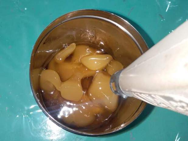
This week's group project was particularly fun for me as I took some weird and interesting materials to test with.
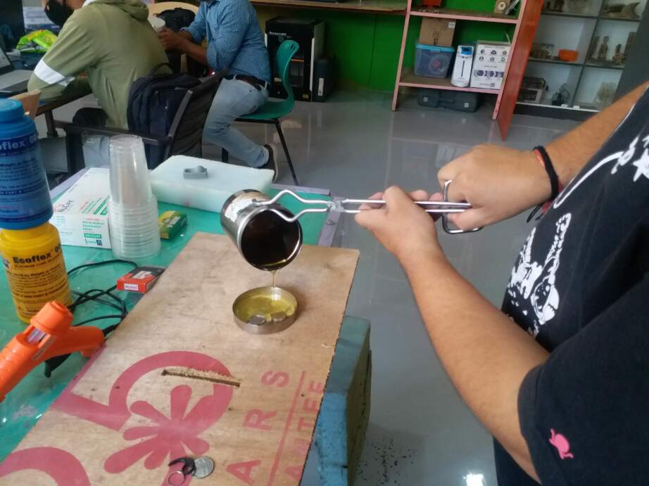
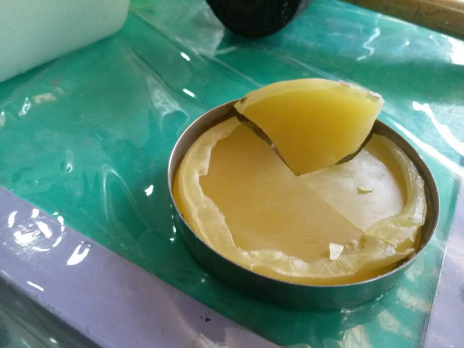
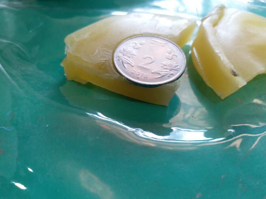
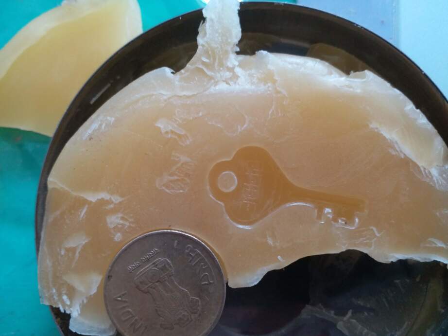
Working with candle wax:
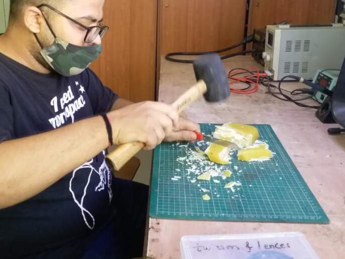
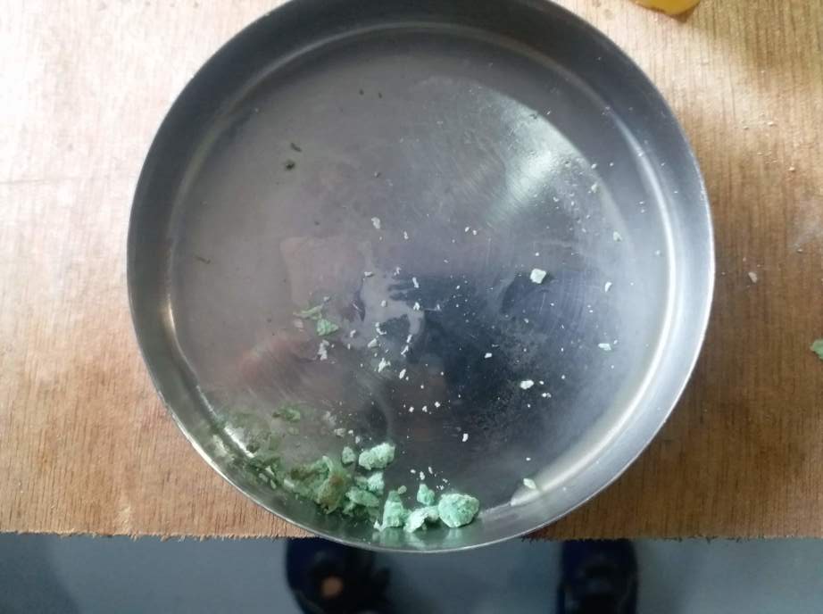
Working with soap
Research for the week
For this week, I took to youtube to look for some inspiration, and I found this video by youtuber Alexander Chappel particularly interesting.
In the video he took a multipart, 3D Printed positive mold that he then used to make a vacuum-formed negative mold that he then used to cast the model in white chocolate. We did not have access to a vacuum forming machine, so I did not proceed with this technique, but i thought it was worth mentioning as it is an inspiring idea. I might try it with a simple 3d printed mold instead of making a vacuum formed mold.
Testing the Chinese Desktop milling machine machine
So I had purchased a cheap chinese Desktop milling machine but I had used it very little, about 5-6 times in total. But I really wanted to find some use out of this machine, so I brought it to Vigyan Ashram for testing it. This is a video of my machine milling some foam:
I used Chillipeppr back then to test the machine. It worked really well but when I tried the same with PCB, I gouged a hole in my base and broke a bit. So I was scared of using the machine. But after using the SRM-20, I developed some confidence and understanding about the process of CNC milling. So here is how I started:
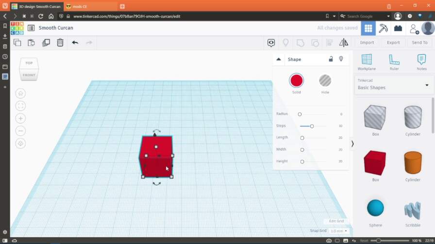
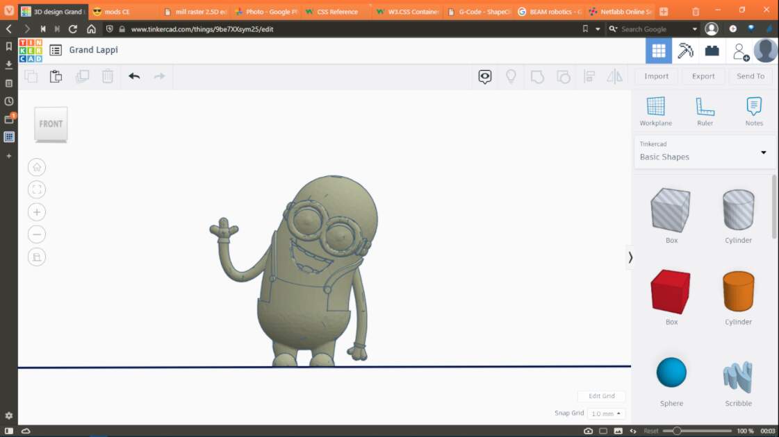
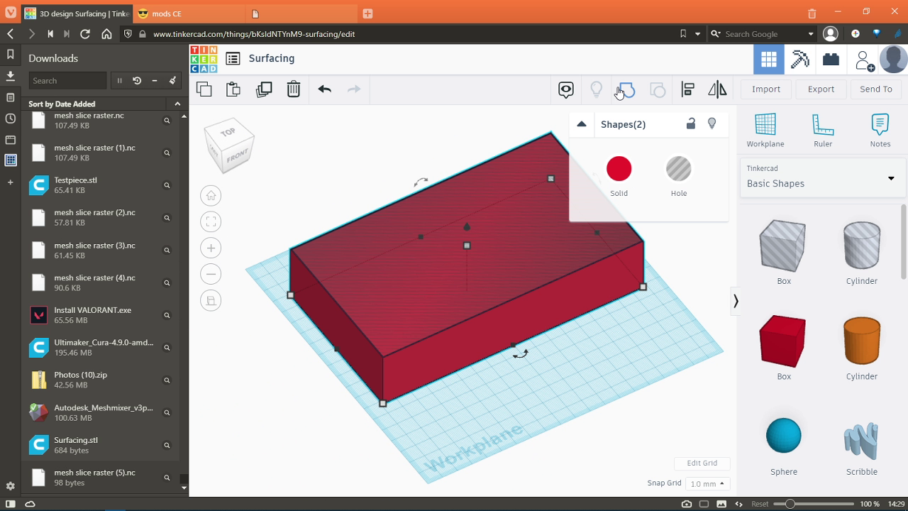
Making a test file in Tinkercad
I made a simple shape to test the machine and establish a toolchain which will be used later to mill my assignment's parts.
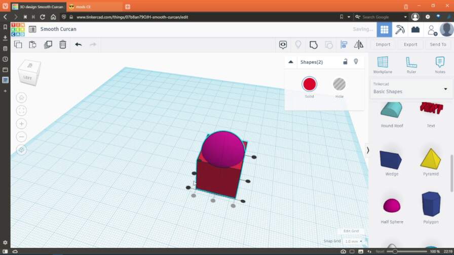
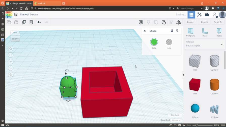
I took a cube and a hemisphere, and I placed the hemispohere on top of the cube. This is what that looked like:
I then placed another cube which was bigger than the model and used another cube as a hole to hollow it out as shown below:
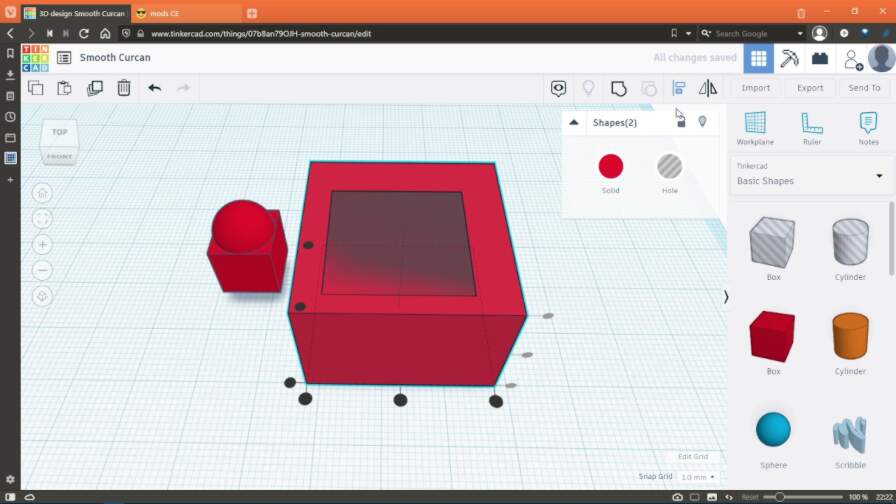
Then I placed the cube and hemisphere shape in this hollowed out cube and grouped everything together:
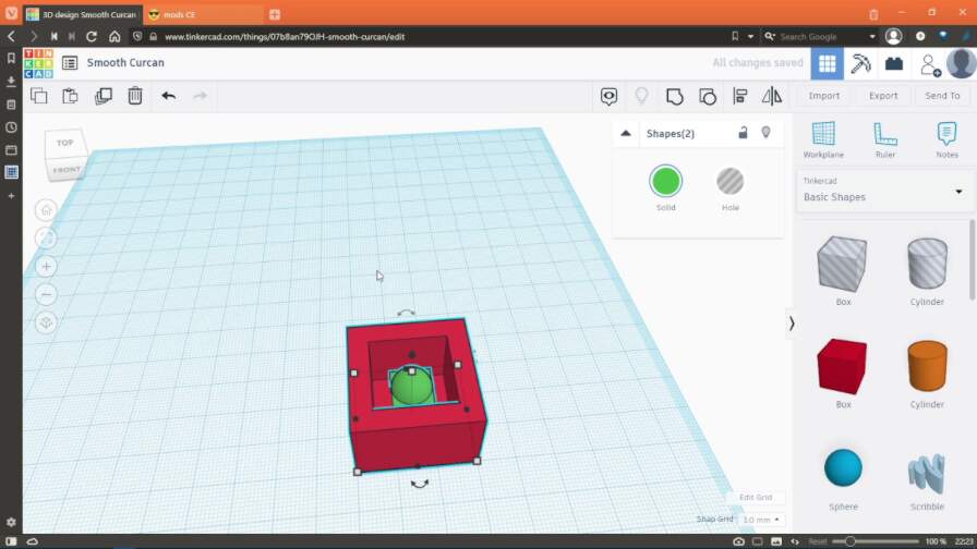
This is the tinkercad model:
STL file of the Test piece
Preparing file for millling using mods
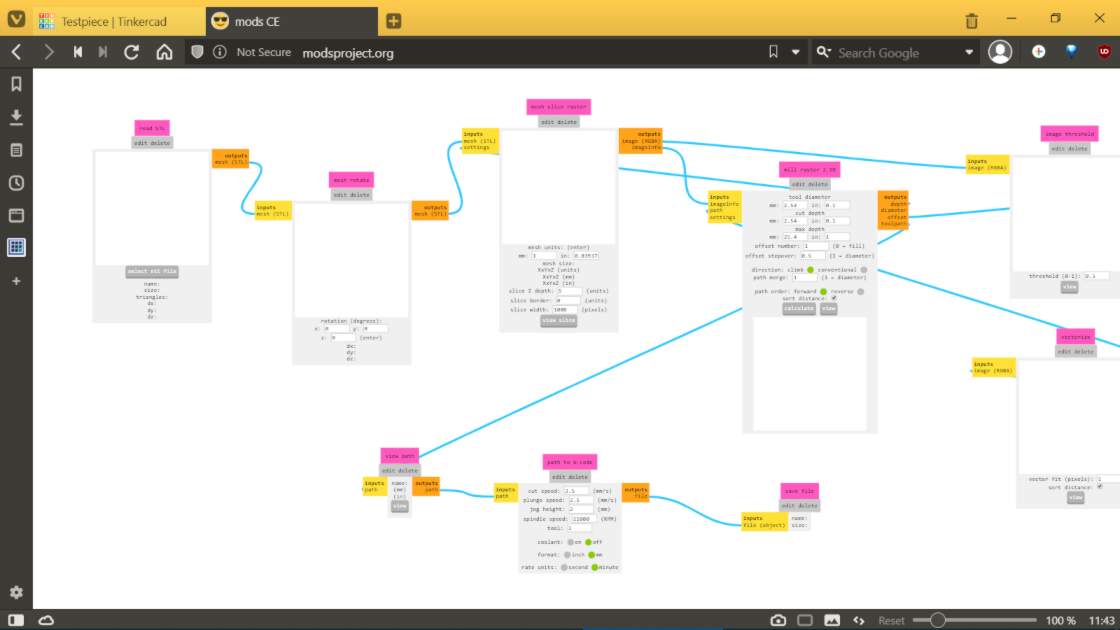
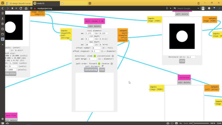
To make the file into the toolpath, I decided to try out mods as Suhas Sir had told us that it can be used for CAM modeling too. I had never tried mods for that purpose and this was the perfect opportunity to do so. Here is what I did:
I opened the milling program by going to programs>open program>gcodes%gt;mill 2.5D stl.
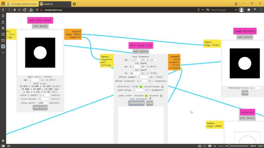
I loaded the aforementioned stl file of the model into the program and set the parameters:
- Tool Diameter: 3.175mm
- Cut Depth: 0.1mm
- Max depth: 20mm
- Offset: 1
- Offset Stepover: 0.5
- Spindle speed: 10000 RPM
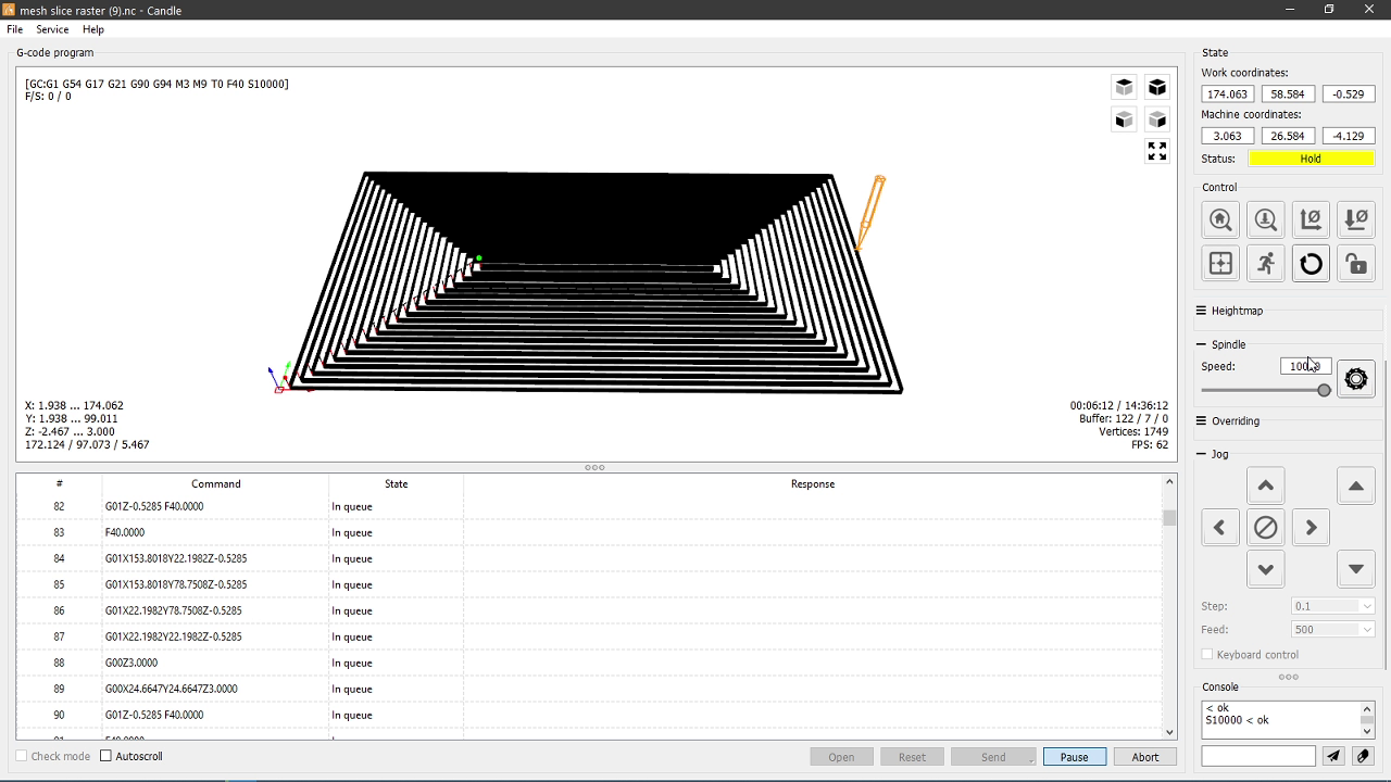
After that I generated the toolpath and loaded it in Candle, which is a software used for sending G-code via USB to GRBL based CNC controllers:
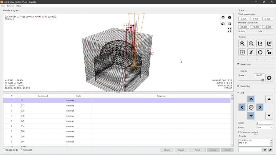
On observing the toolpath in Candle, I noticed something. The machine was not clearing any material above the 3D object before starting milling there.
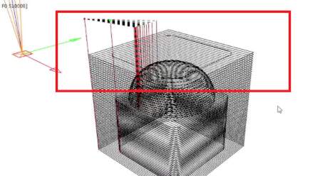
I realised that this was happening due to me setting the offset to one. I reset it to zero and I also set the cut depth to 0.3mm to save some time. Then I generated a new toolpath:
This is what it looked like in Candle. Notice the new toolpaths above the shape.
Preparing the machine
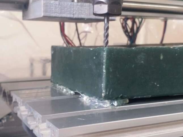
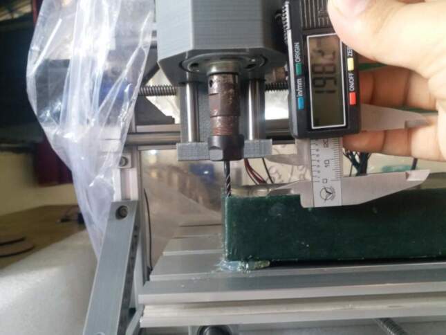
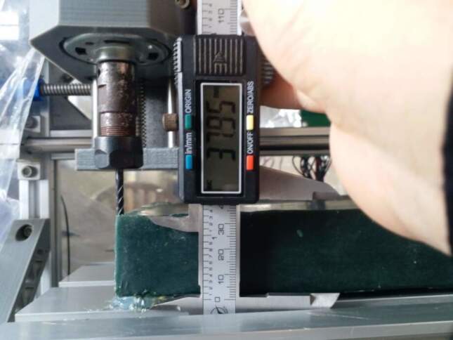
After I was happy with the toolpath, I set up the machine with a 1/8 inch 4 flute flat endmill. The machine has a 1/8 inch collet which i used to attach the bit to the spindle motor.
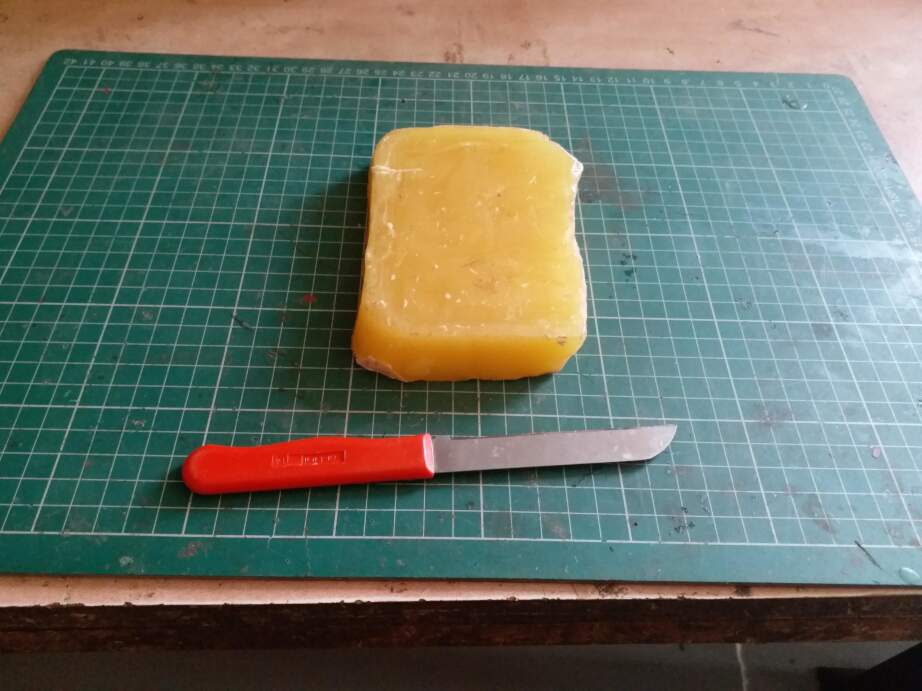
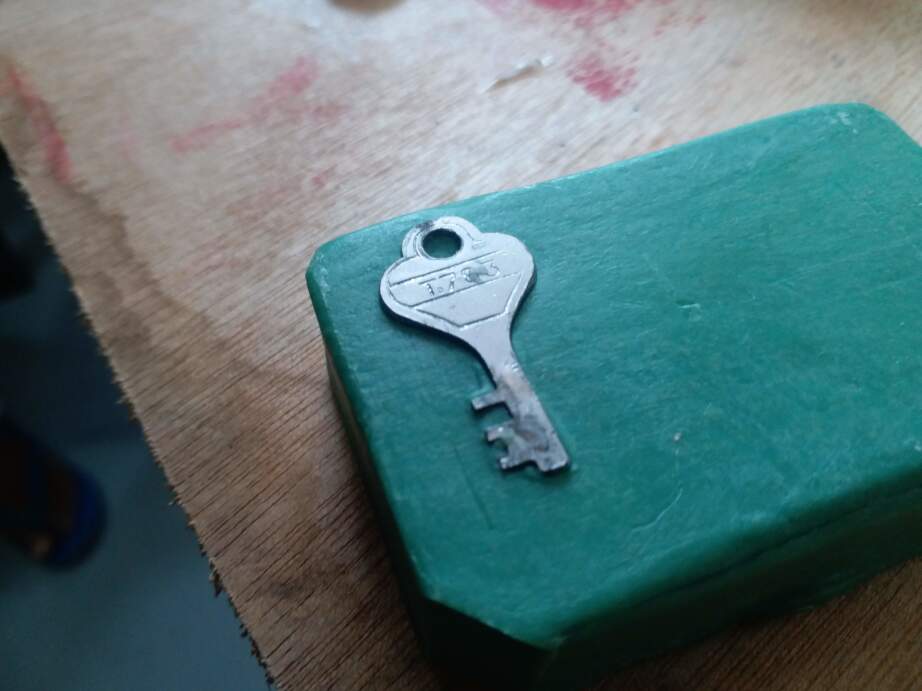
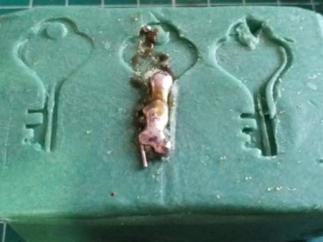
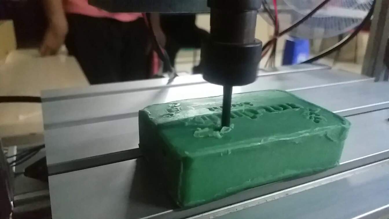
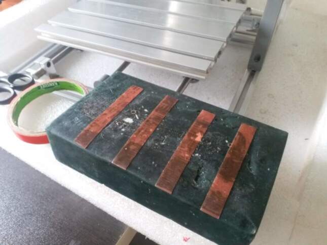
Since I did not want to waste any machining wax in my trial, I decided to use a bar of soap as my testing material. It was pretty dense so I thought that it would be a good substitute for the machining wax.
I used some highly adhesive double sided sticky tape to secure the soap onto the platform.
Then I positioed the endmill manually by moving the x, y and z axes by hand in such a way that the endmill was resting in the front right corner of the upper surface of the soap.
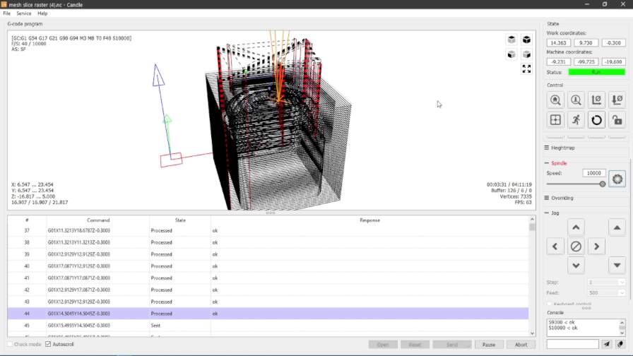
After making sure that everything was set properly, I started sending the g-code to the machine and it started milling successfully.
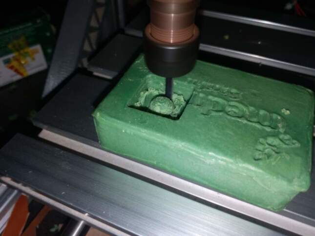
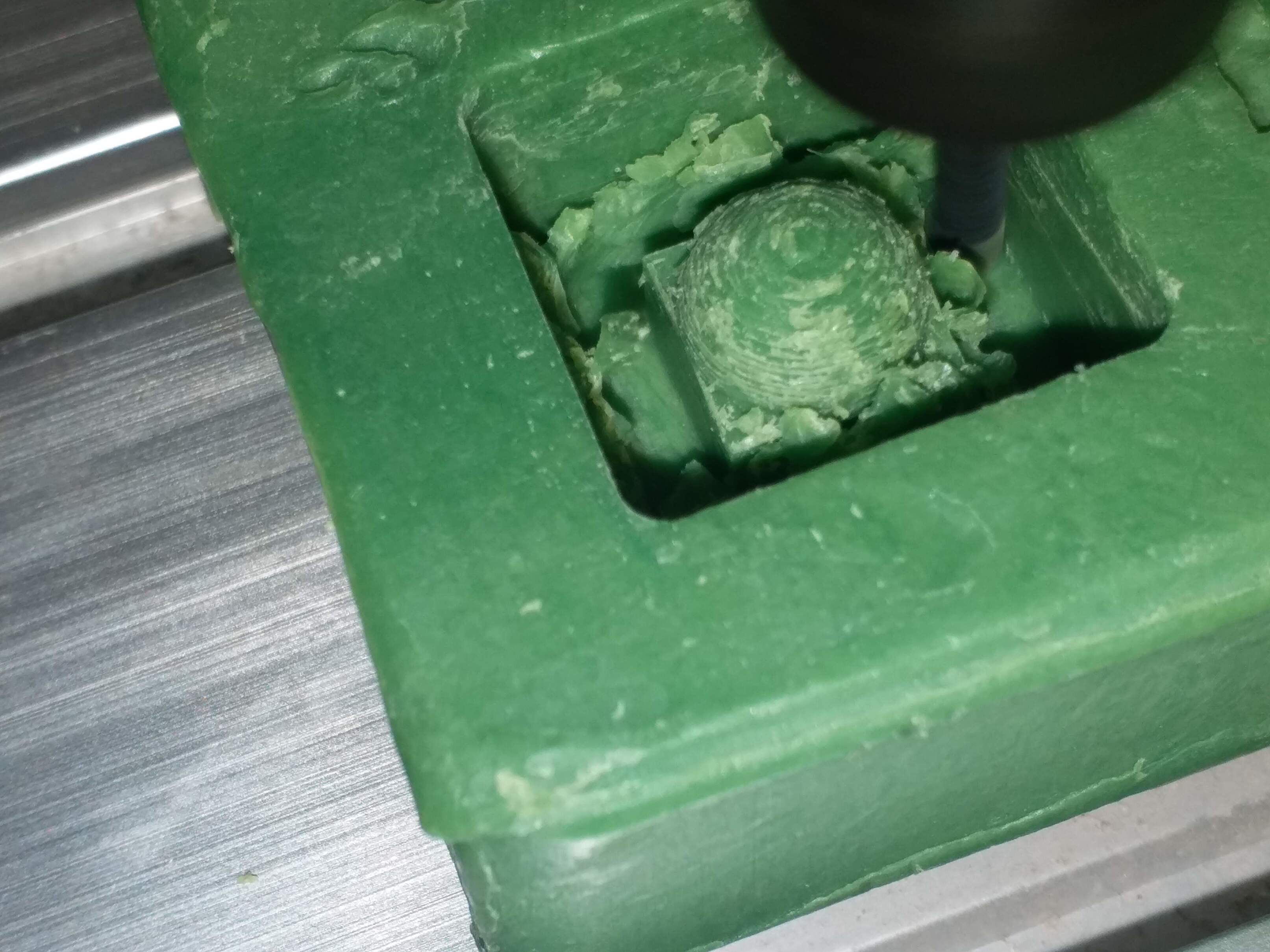
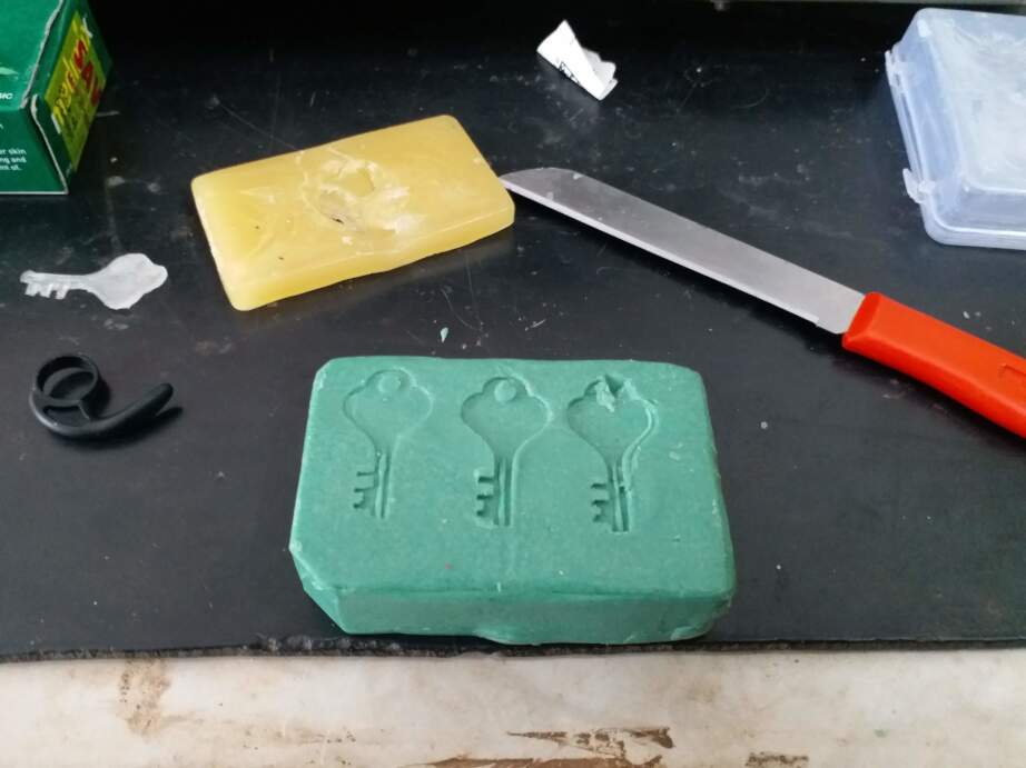
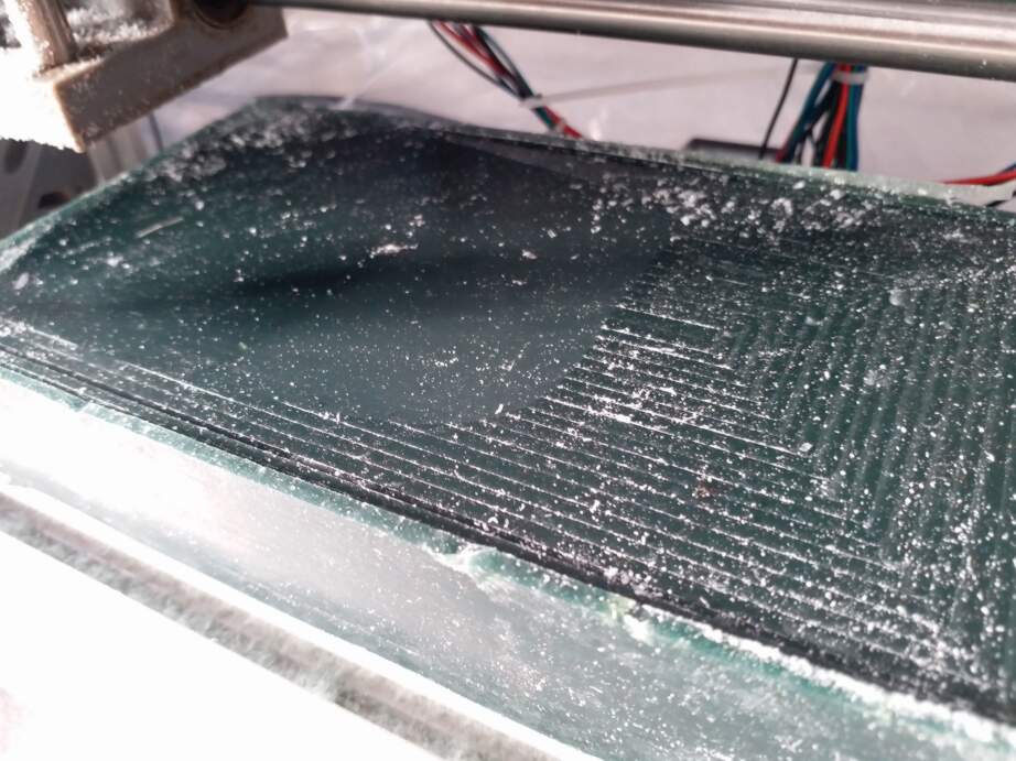
Results
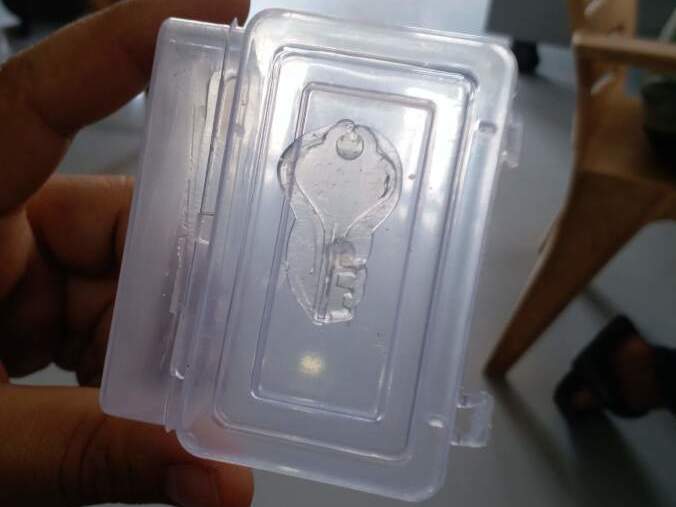
After the milling process was over, I got this result:
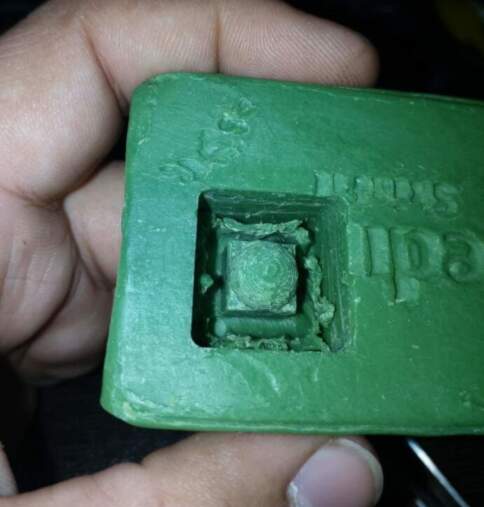
This result made me confident enough in the tool chain that I had established and also gave me an idea of the accuracy of mods.
Final model
Rhino File
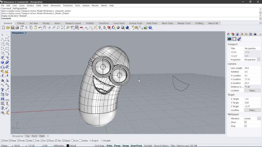
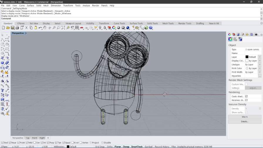
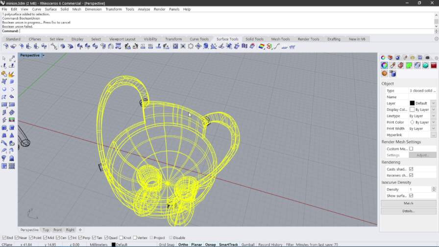
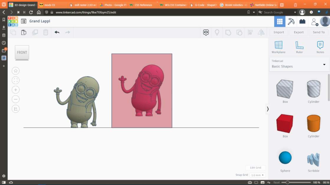
To design the 3D file for this week, I wanted to make something that pushes the boundary of this process. So I took a very curvy, organic shaped character of a minion for my object since it has a fairly complex geometry.

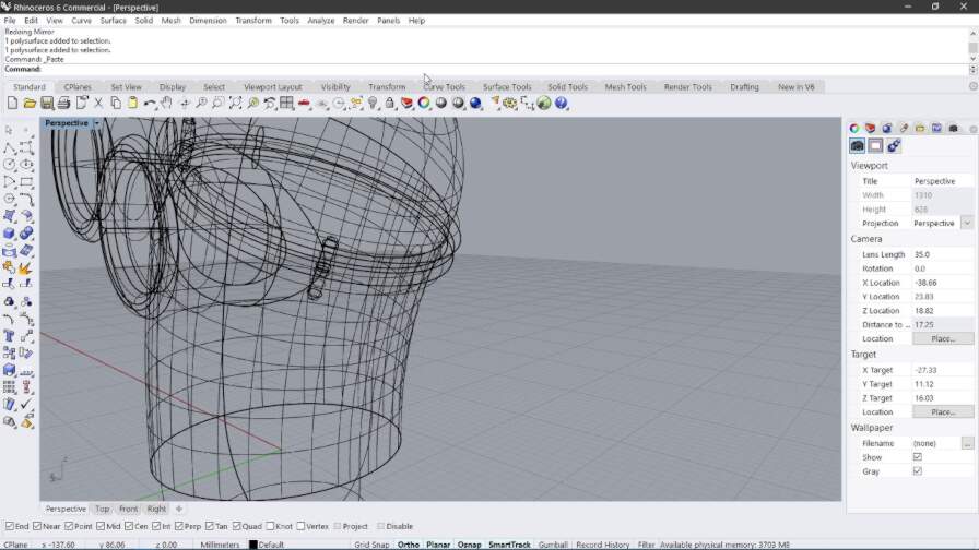
I then used Rhino to create a 3D model of the minion. Here is what I did:
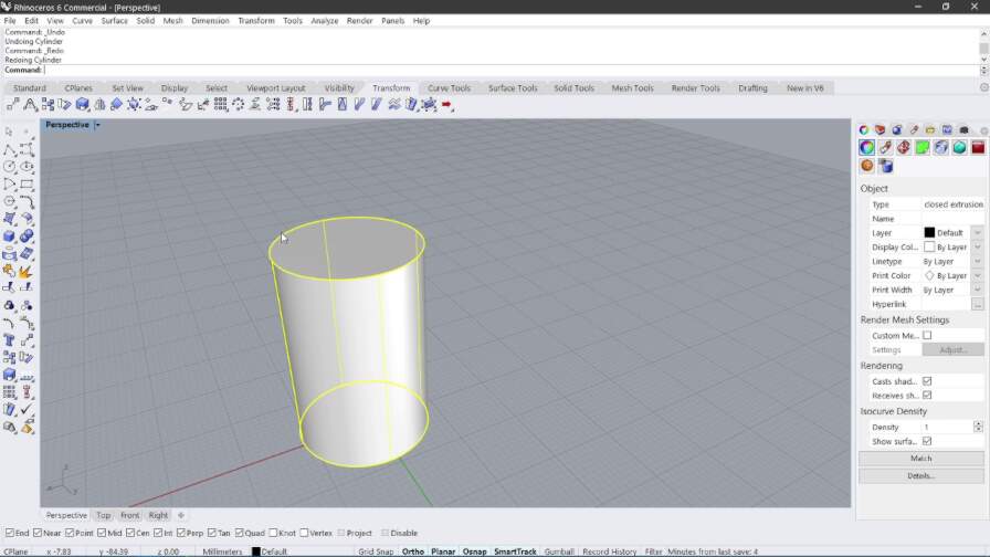
I started with a cylindrical shape as the base of the body.
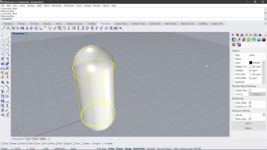
I added two spheres, one at each end of the cylinder:
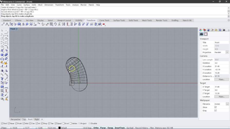
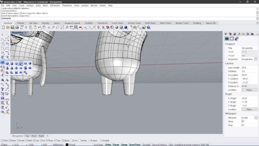
I then BooleanUnioned the whole shape and bent it by an arbitrary amount to make the base of the body.
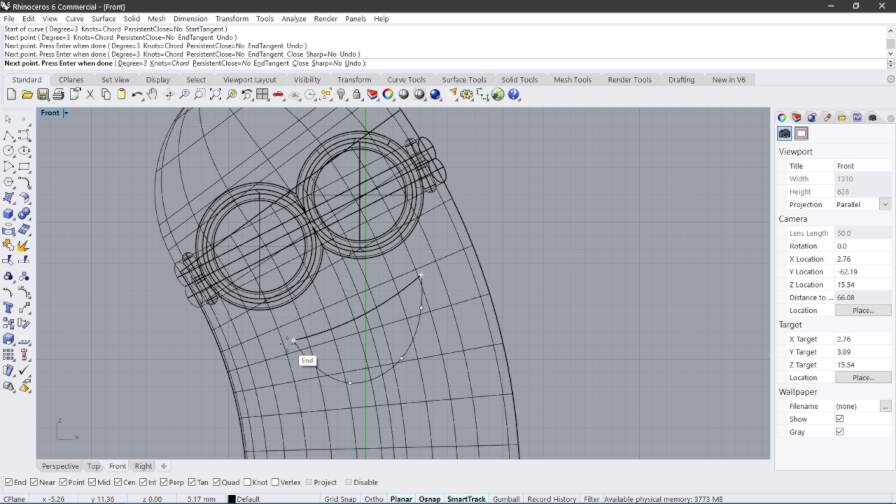
After that I added cylinders for the eyes
And some more cylinders for the glasses
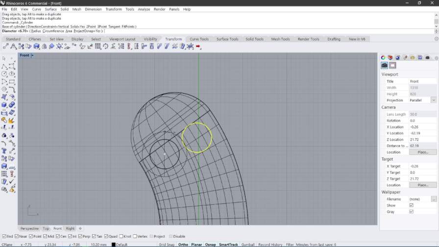
Then I shaped the goggles

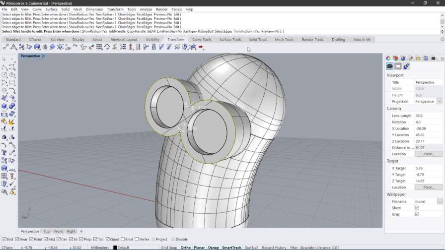
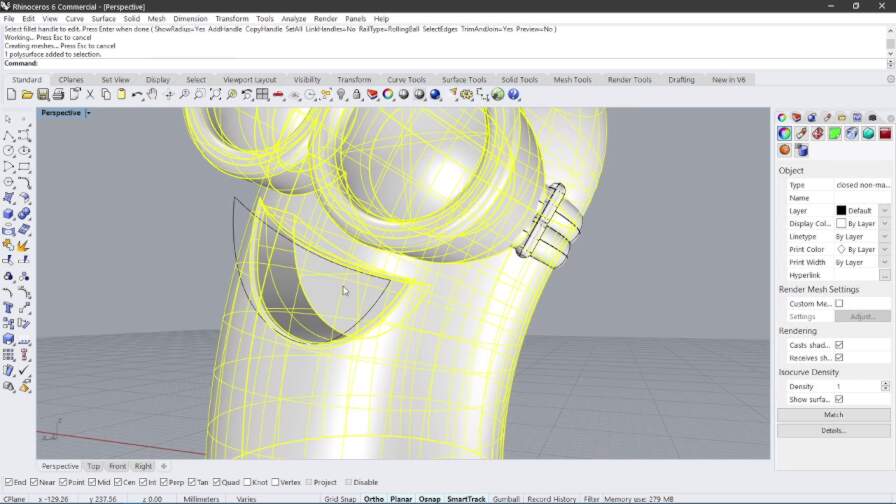
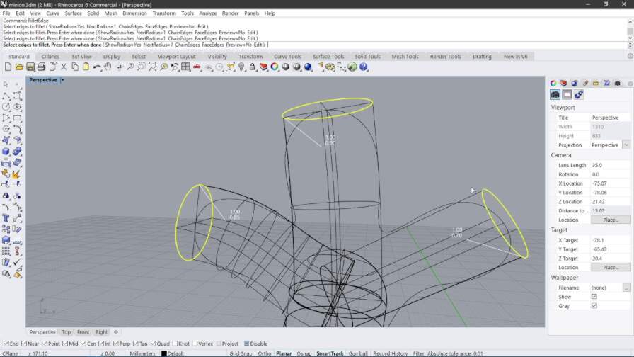
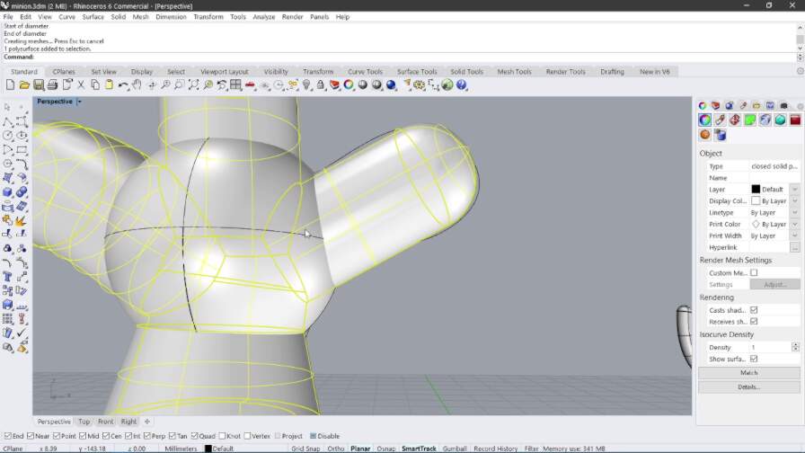
Then I filleted the edges
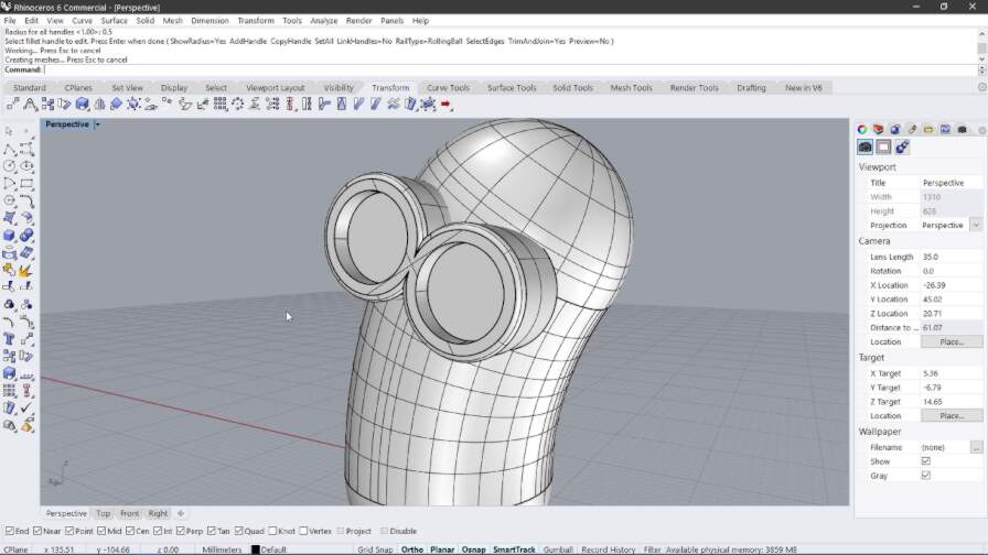
Then I added spheres to make the eyes
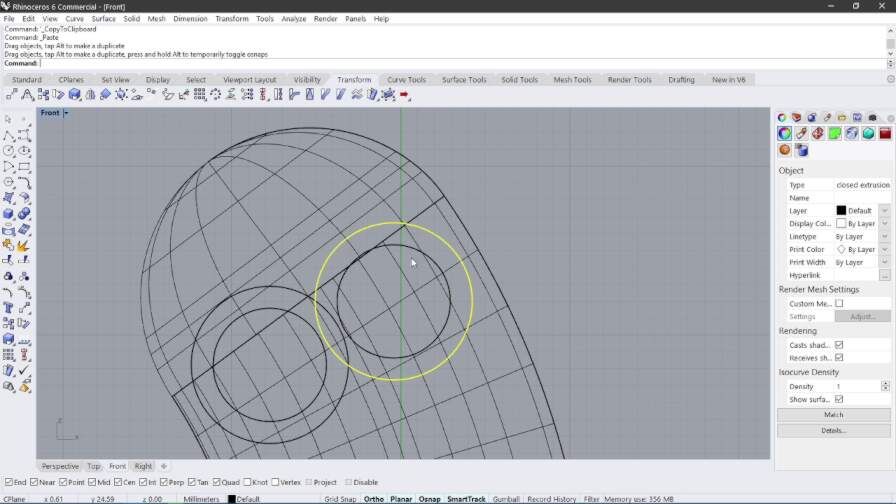
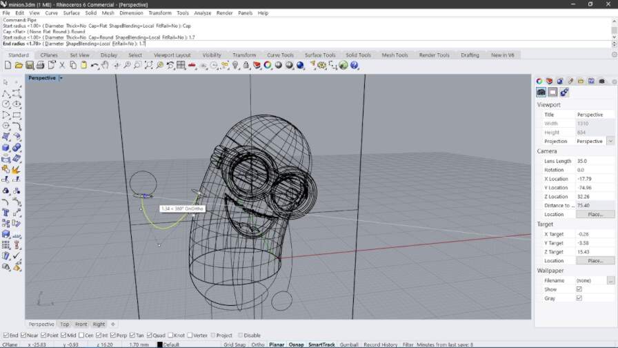
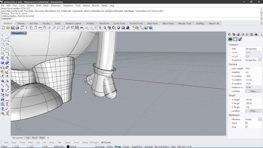
Then I wanted to add a hinge for the strap of the goggles. I did that by creating a cylinder and filleting the edges.
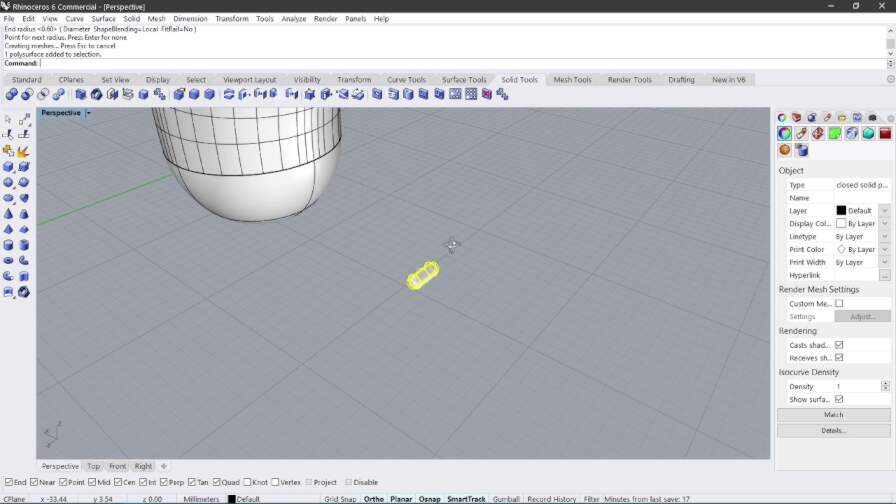
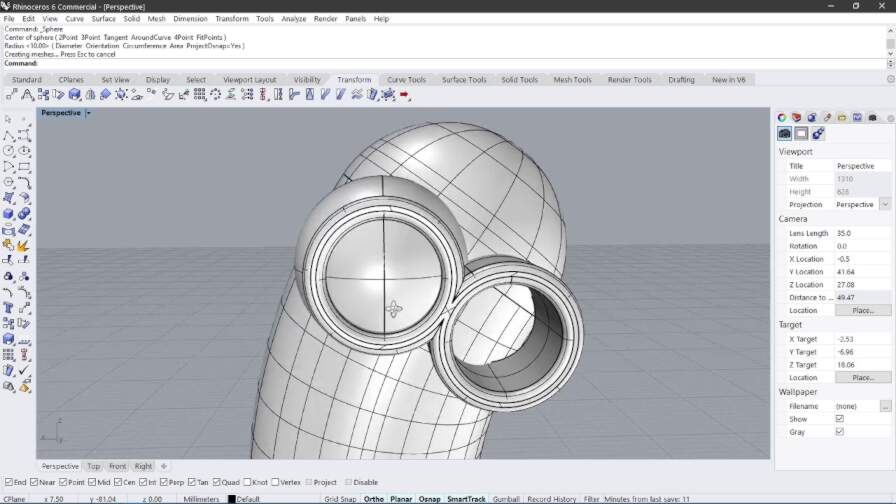
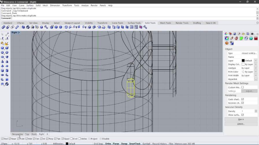
Then I placed the cylinders next to the goggles and rotated it.
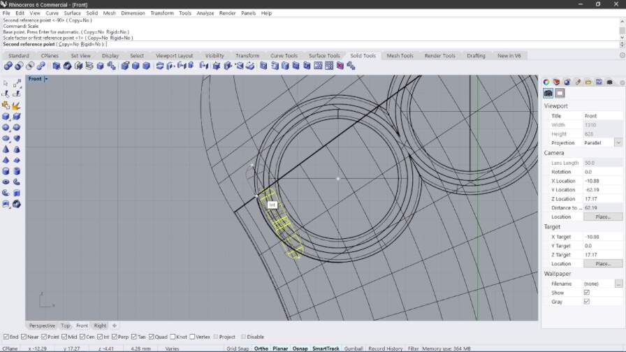
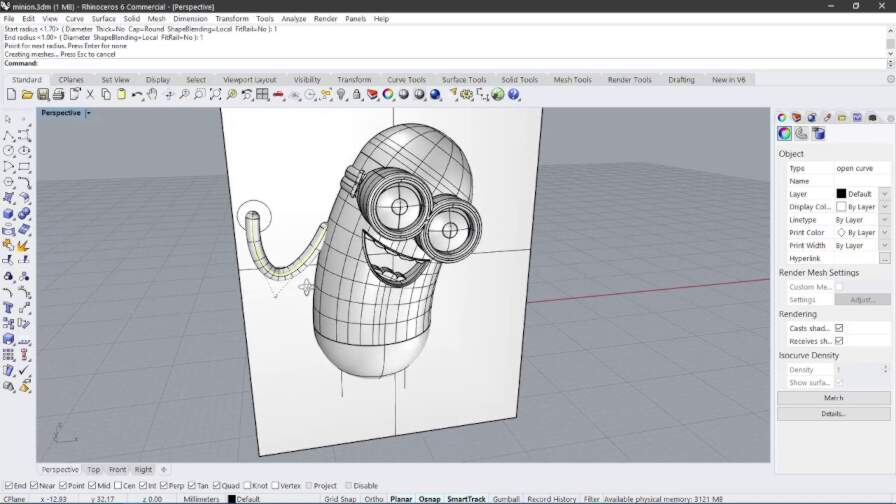
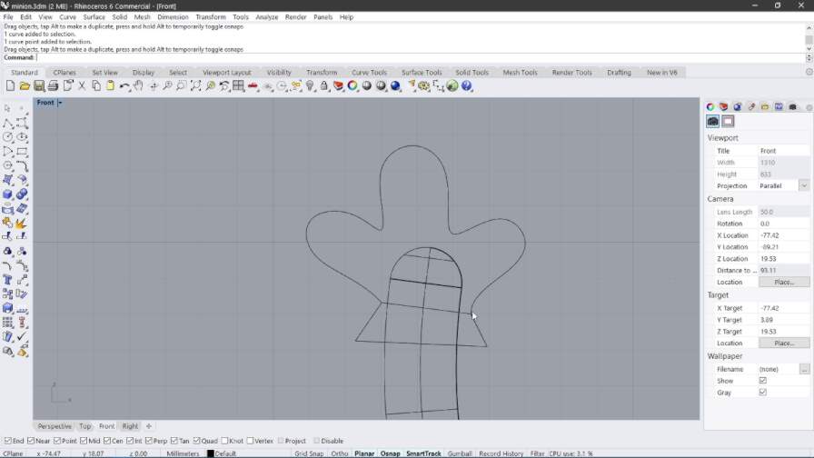
Then I made the strap by using a torus and elongating it in one direction.
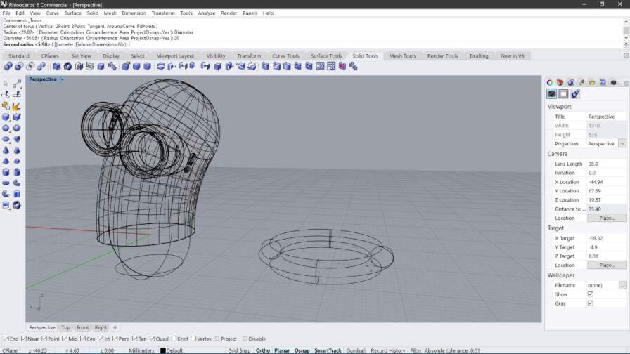
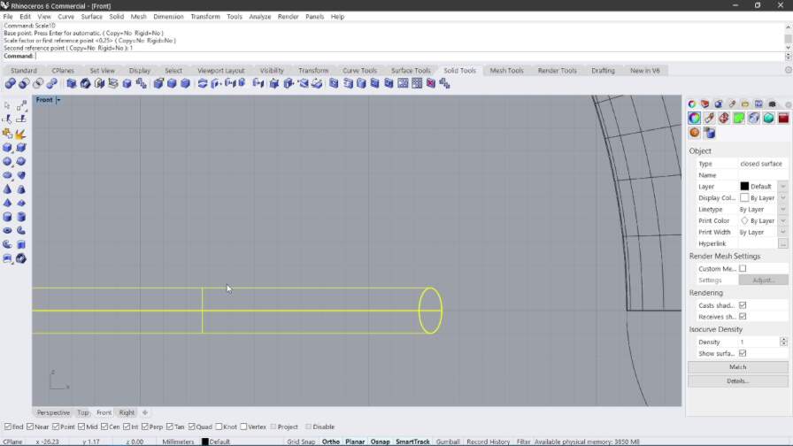
I made the strap more realistic by doubling the elongated torus and shifting one of the toruses on top of the other. This is what it looked like:
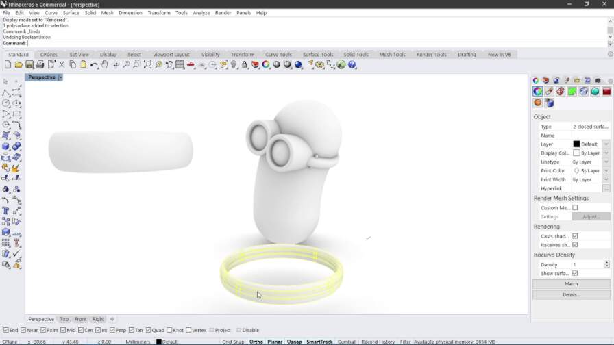
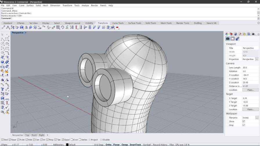
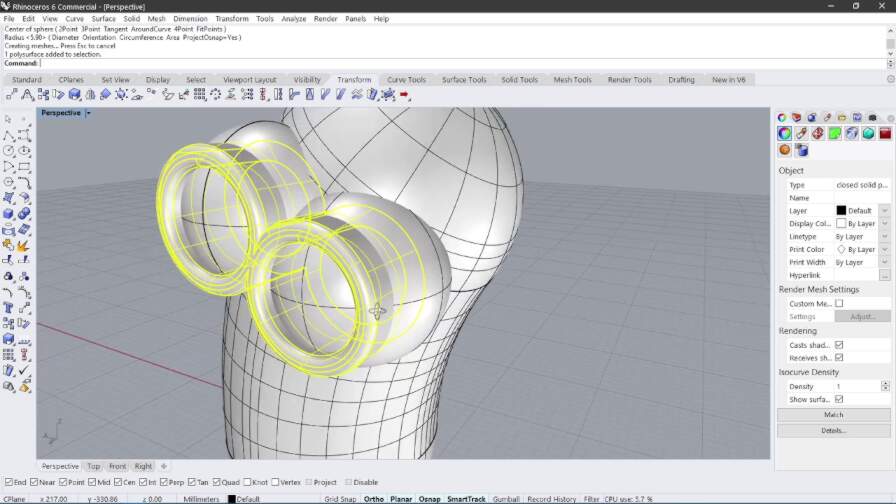
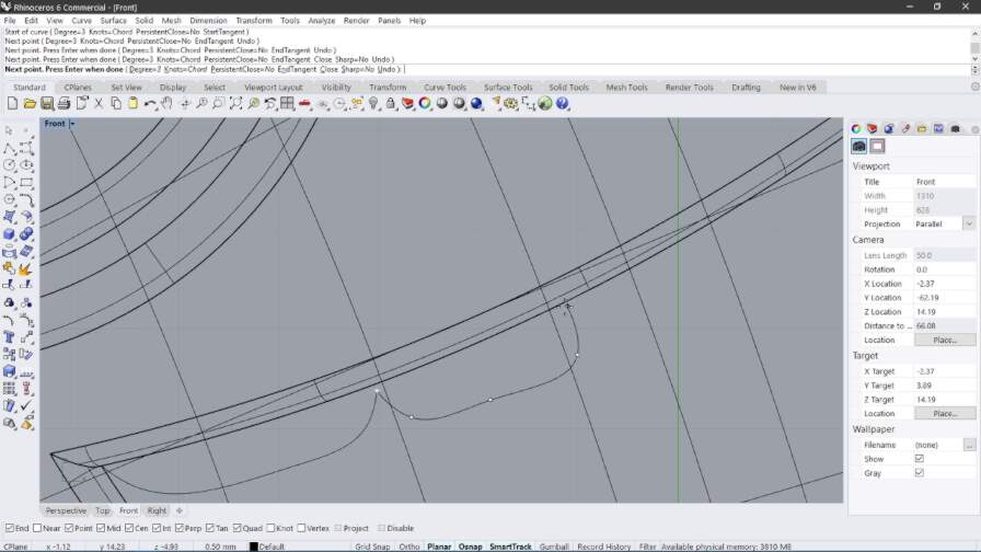
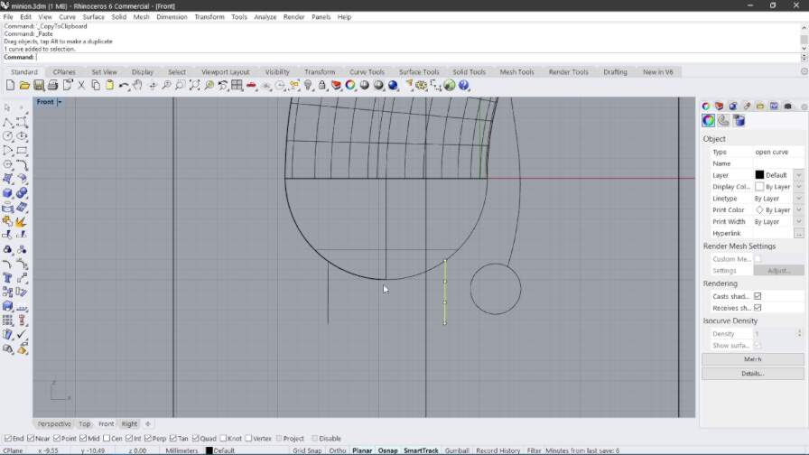
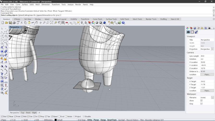
After this I proceeded to make the mouth of the minion by using the curved line tool, extruding the shape, and then cutting it out of the model by Boolean Difference
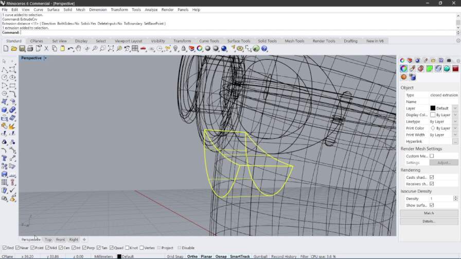
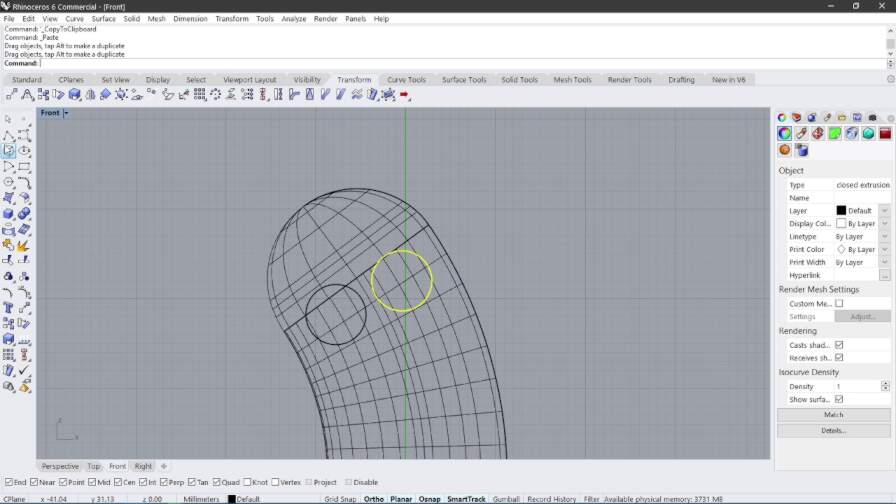
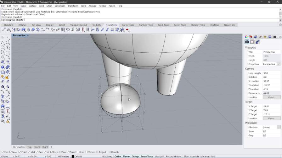
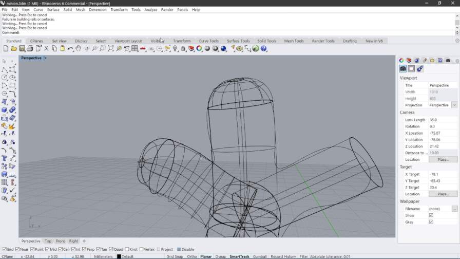
After that
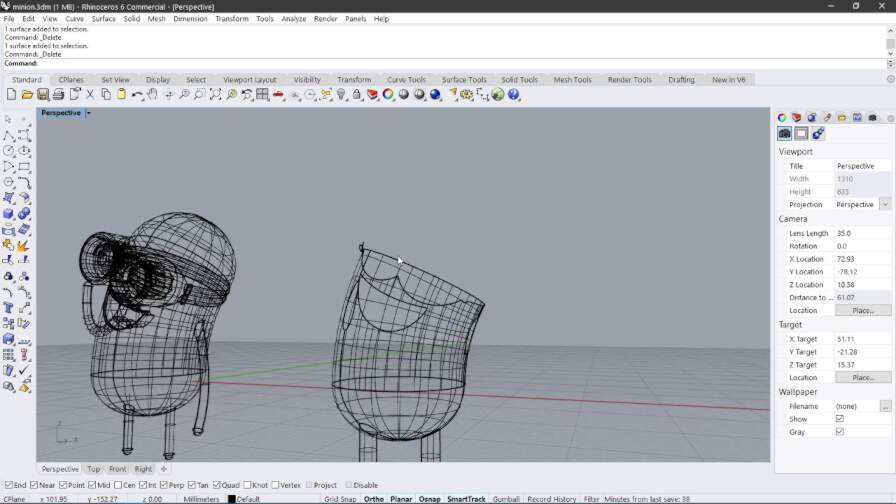
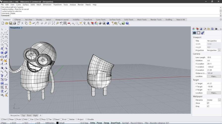
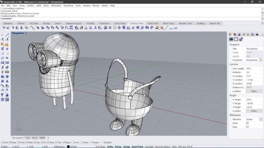
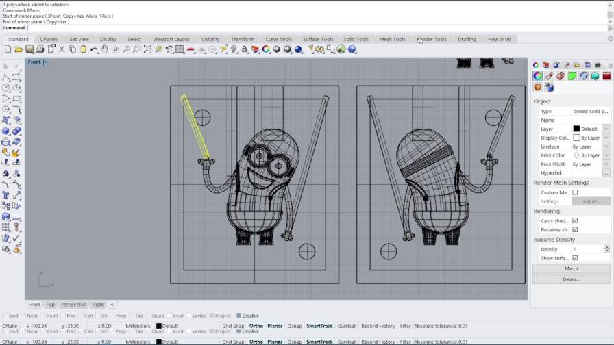
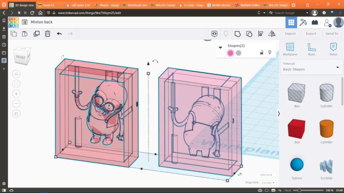
Mold of the minion's front
Mold of the minion's back


Preparing the machine
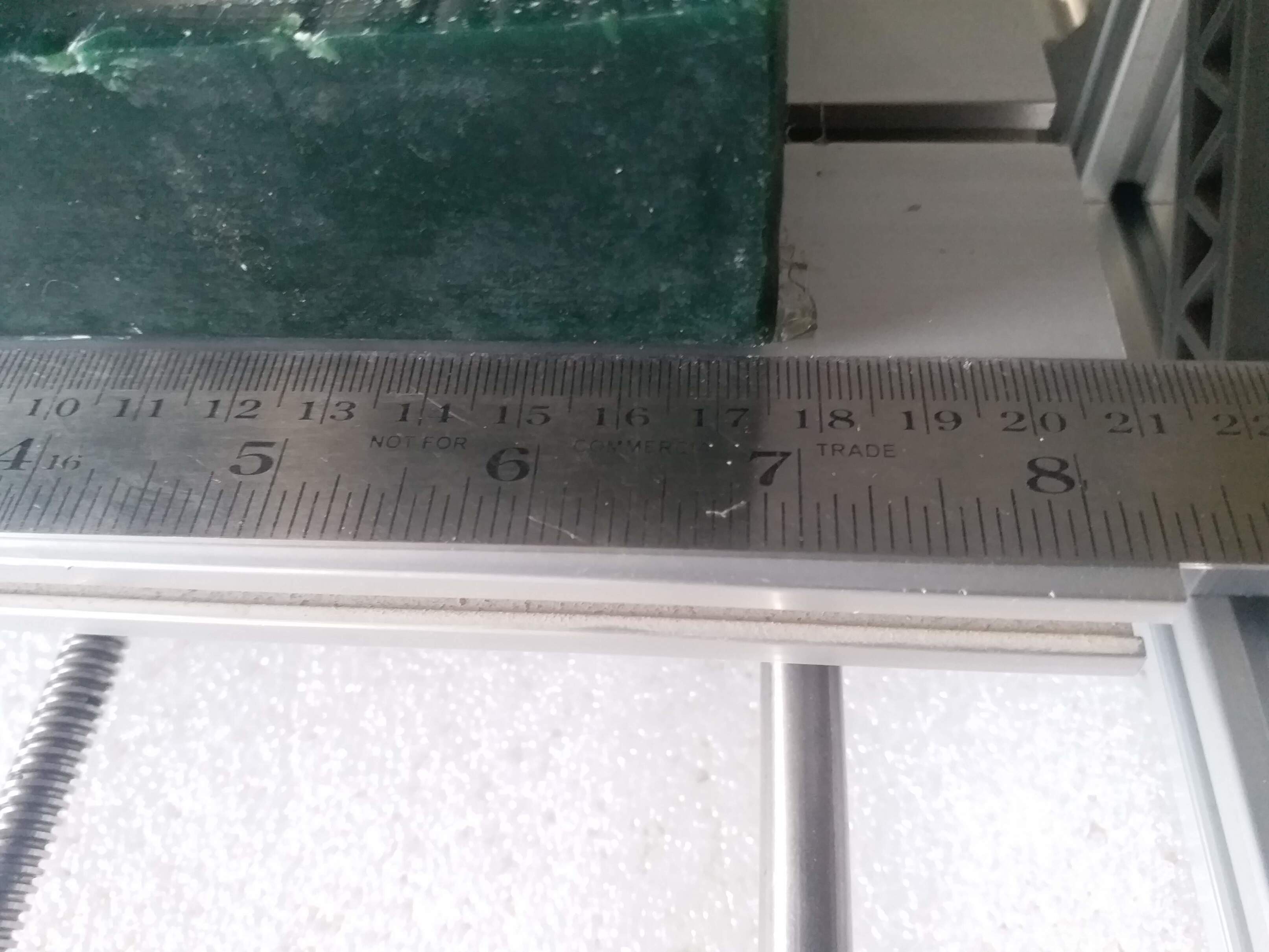
In order to prepare the machine, I took the machining wax block and stuck it to the base with some double sided sticky tape.
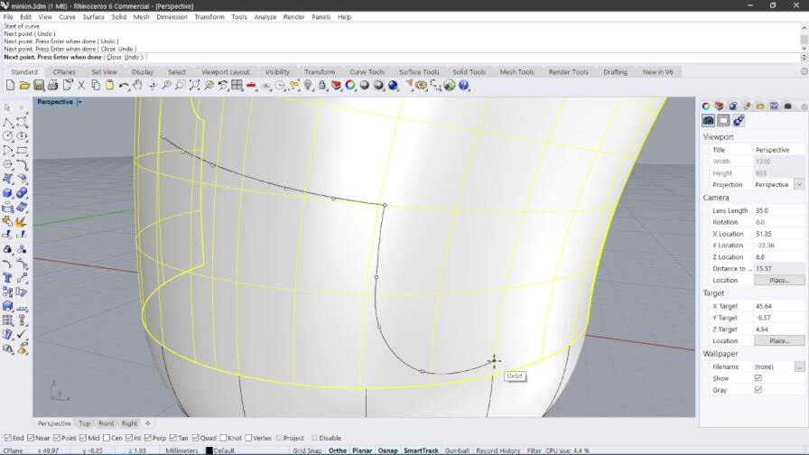
Surfacing
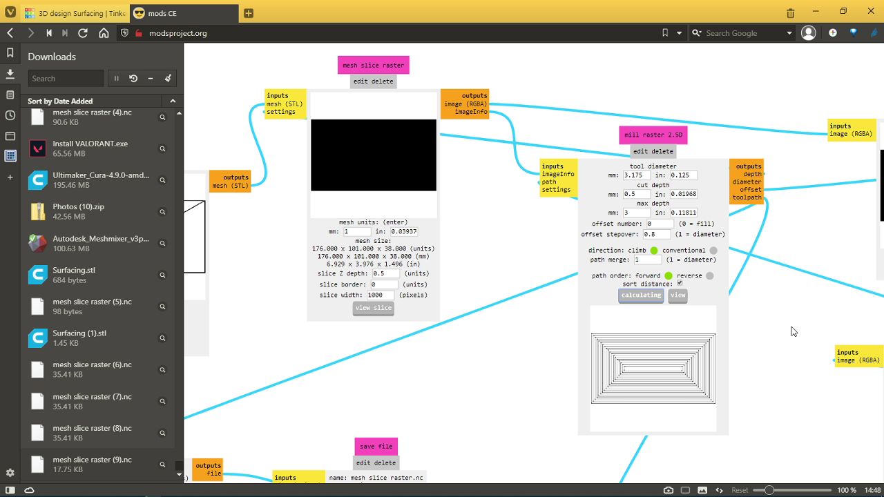
Preparing CAM with mods
Front half
Second half