Model (raster, vector, 2D, 3D, render, animate, simulate, ...) a possible final project,
Compress your images and videos,
And post a description with your design files on your class page
Assignment Requirement
Status
Modelled experimental objects/part of a possible project in 2D and 3D software
Completed
Shown how I did it with words/images/screenshots
Completed
Included my original design files
Completed
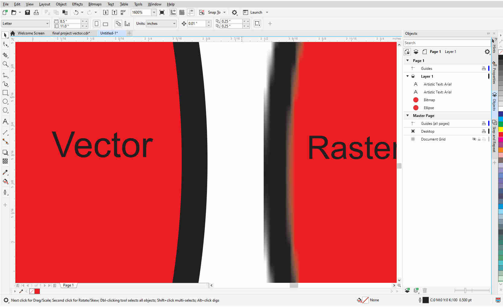
Vector images are made up of paths and nodes. These images can be zoomed in all the way and will still be seen solid without any sort of distortion.
Raster images are comprised of dots or pixels. The more dots or pixels the image contains
the higher is visible quality. These images, if zoomed in you will begin to see that the image is made up of tiny squares, and if zoomed in even more the image becomes distorted or what we called pixilated.
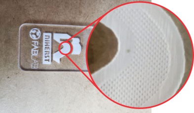
The laser cutter can detect the difference between a raster and vector image. This is why there are settings for both images. This will normally cut a vector and engrave a raster. If you look closely at an engraved object, you will see the engraving is made up of dots pierced at different levels.
There are many graphic software that can be used, but for this assignment but I will use CorelDraw graphic suite. CorelDraw is a vector illustration software and can also work with raster images and can convert vector to raster and vice versa. Embedded in CorelDraw is Corel Photo Paint which does editing of raster images.
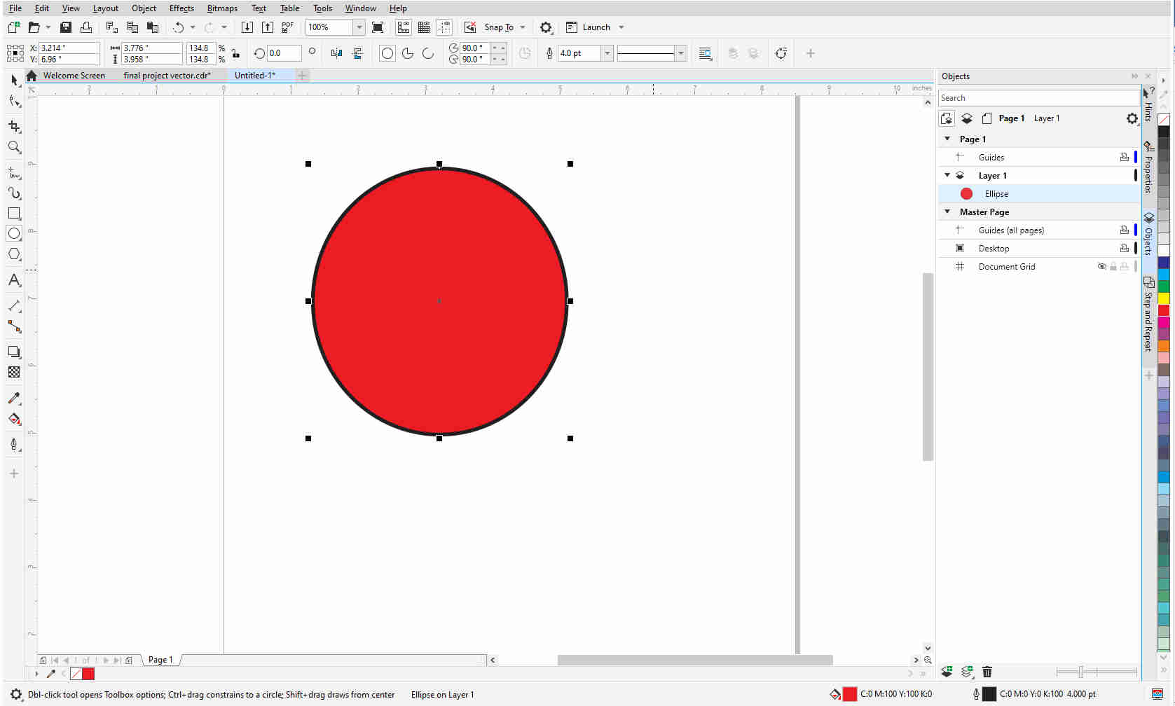
These are the most common tools used for vector drawing– node editor, various line tools, elliptical and rectangular and basic shapes such as hexagons or stars.
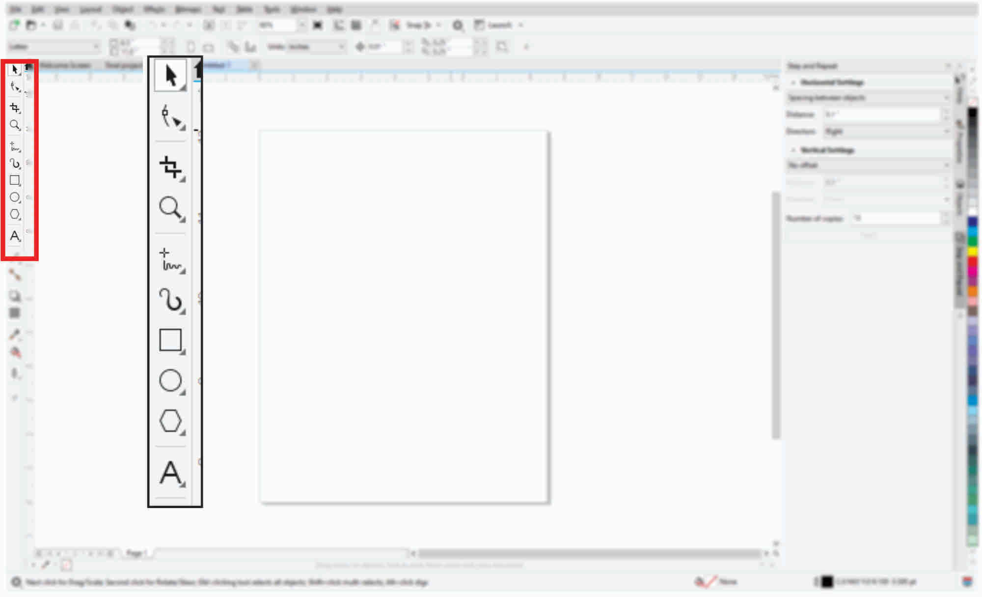
If a vector drawing makes an entire loop, that object can then be filled with a color.
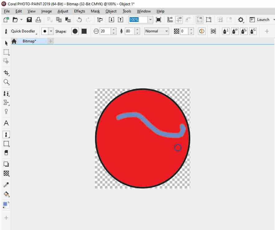
By going to Bitmap tab, I select convert to bitmap and this will now convert the vector image to a raster.
I can now select edit bitmap and this will open the image in Corel Photo Paint where I can edit the raster image. On completion of editing, I click save and the image back in CorelDraw will display those edits.
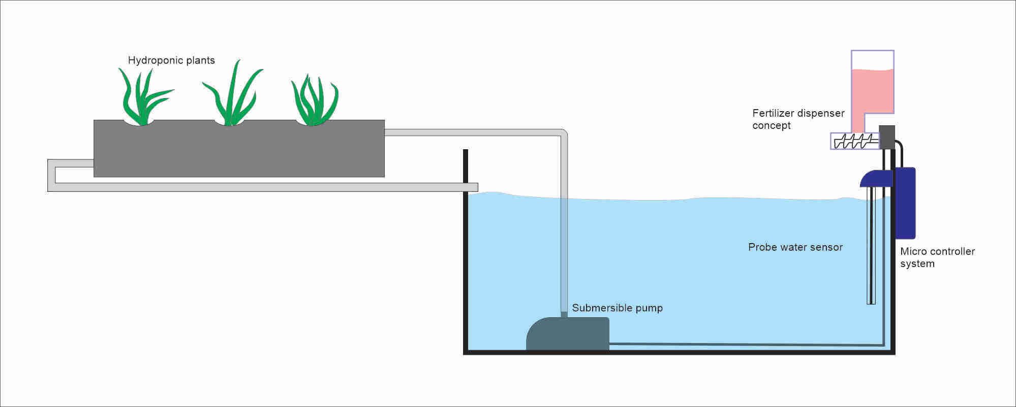
This is a vector sketch of my final project using CorelDraw.
There are many CAD software to design a 3D part. I tried my hand at Fusion 360 and though it is an excellent software I think I need a little more practice with it. For this assignment I used FreeCAD which is an open-source software. I found
FreeCAD easy to use and I can really do a lot with the features it has.
I am still not too experienced with the software just yet so I looked at some basic tutorials on YouTube (links will be provided) just to grasp key features and techniques that I can try out. For this week’s assignment I decided to
draw a part component that I will require for my final project.
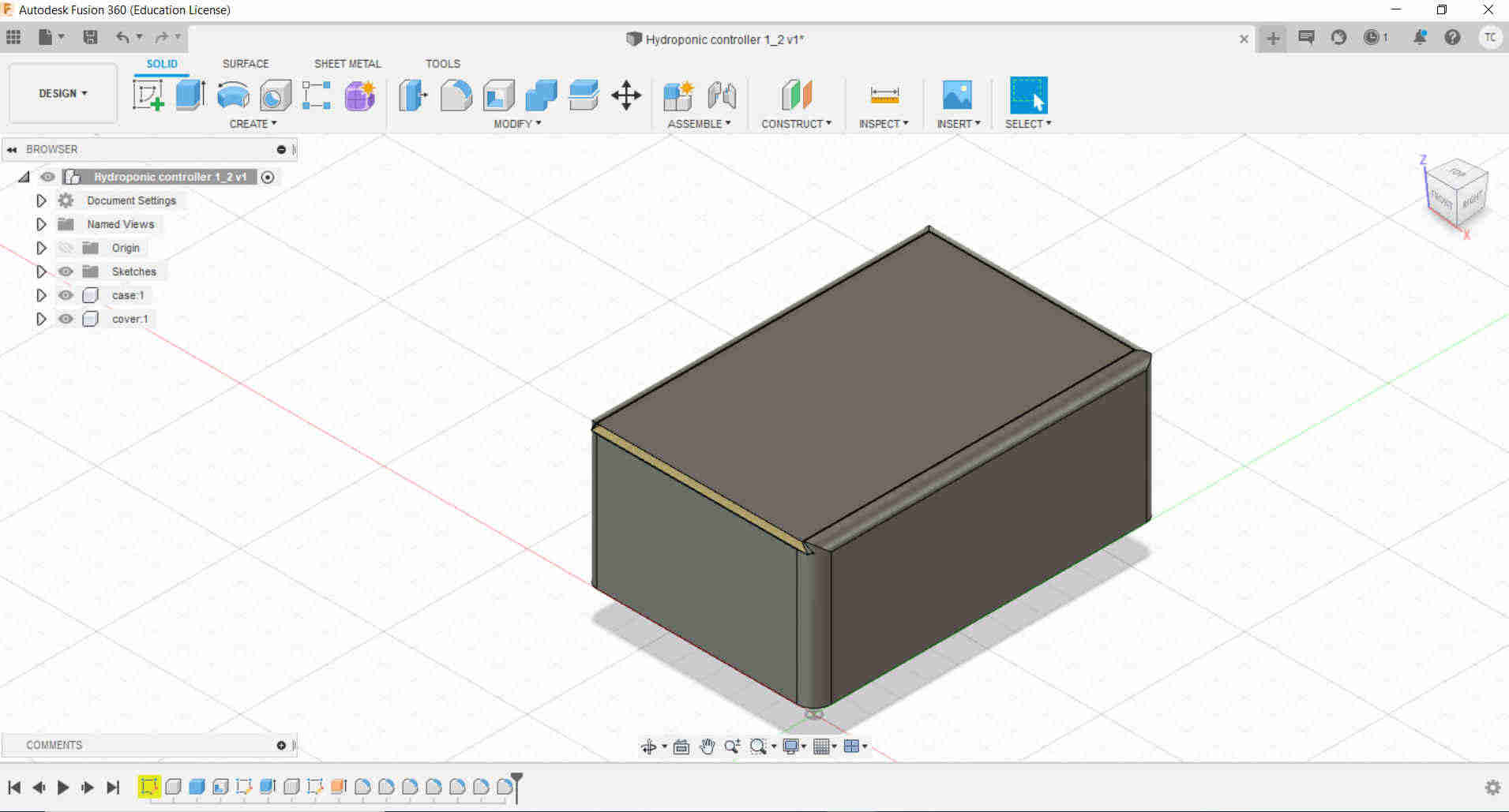
This is a design I did in Fusion 360 as I followed a YouTube tutorial.
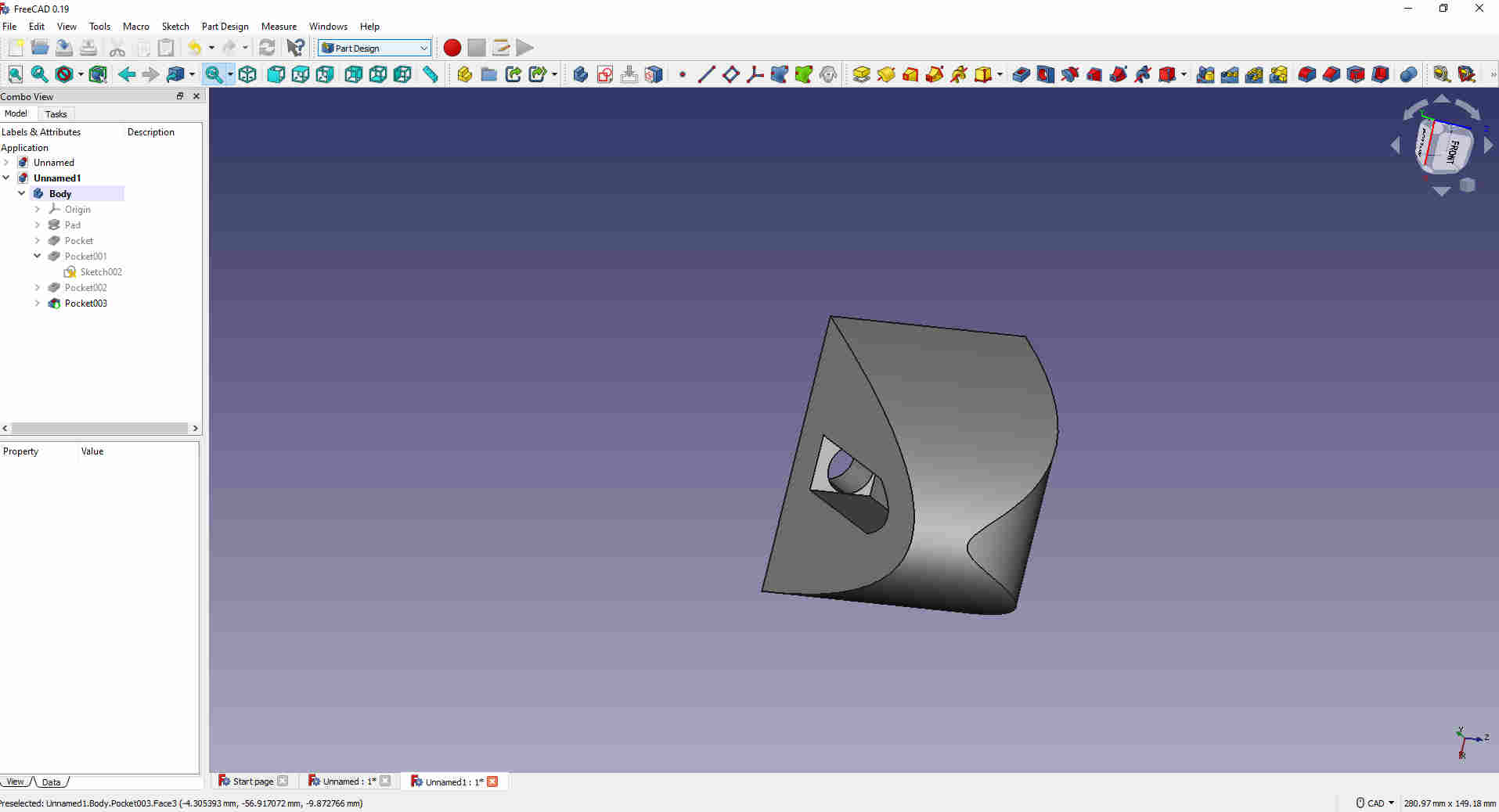
This is the part I attempted to draw this week in FreeCAD.
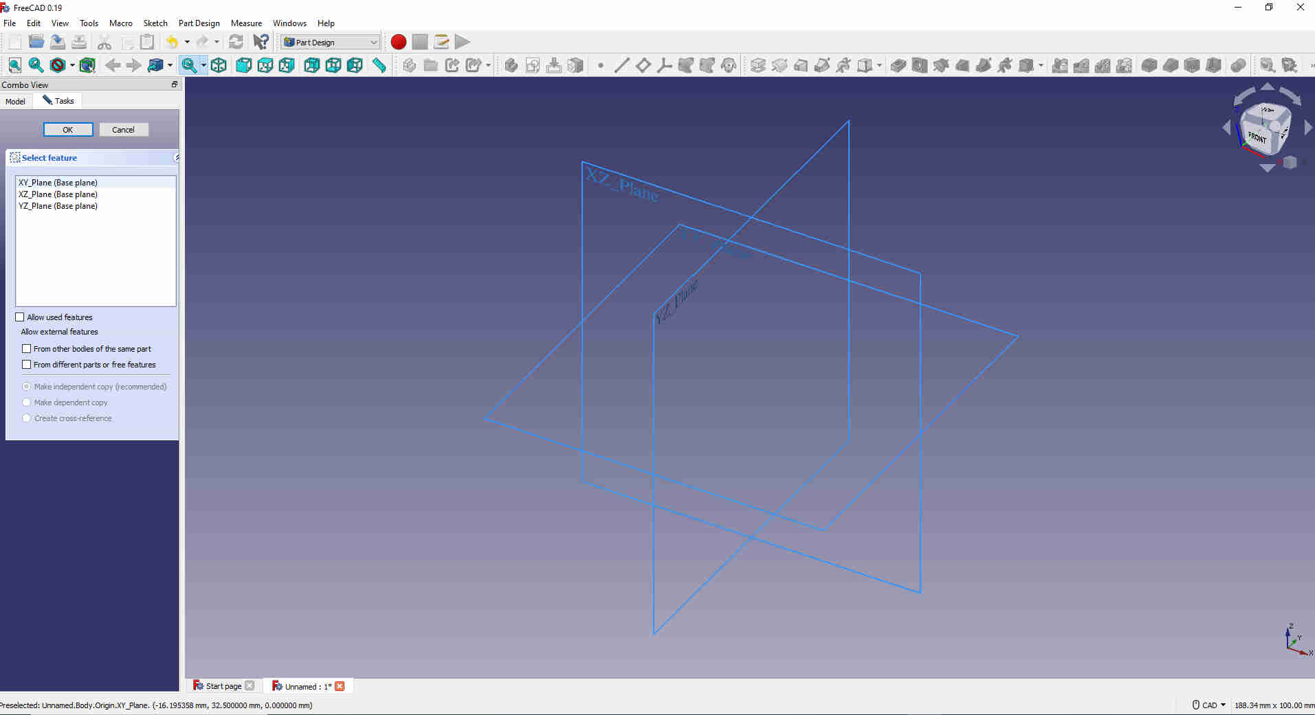
I selected the part design workbench and created a new body.
My final product will be a 3D object but first I must do a 2D sketch and I used the XZ plain.
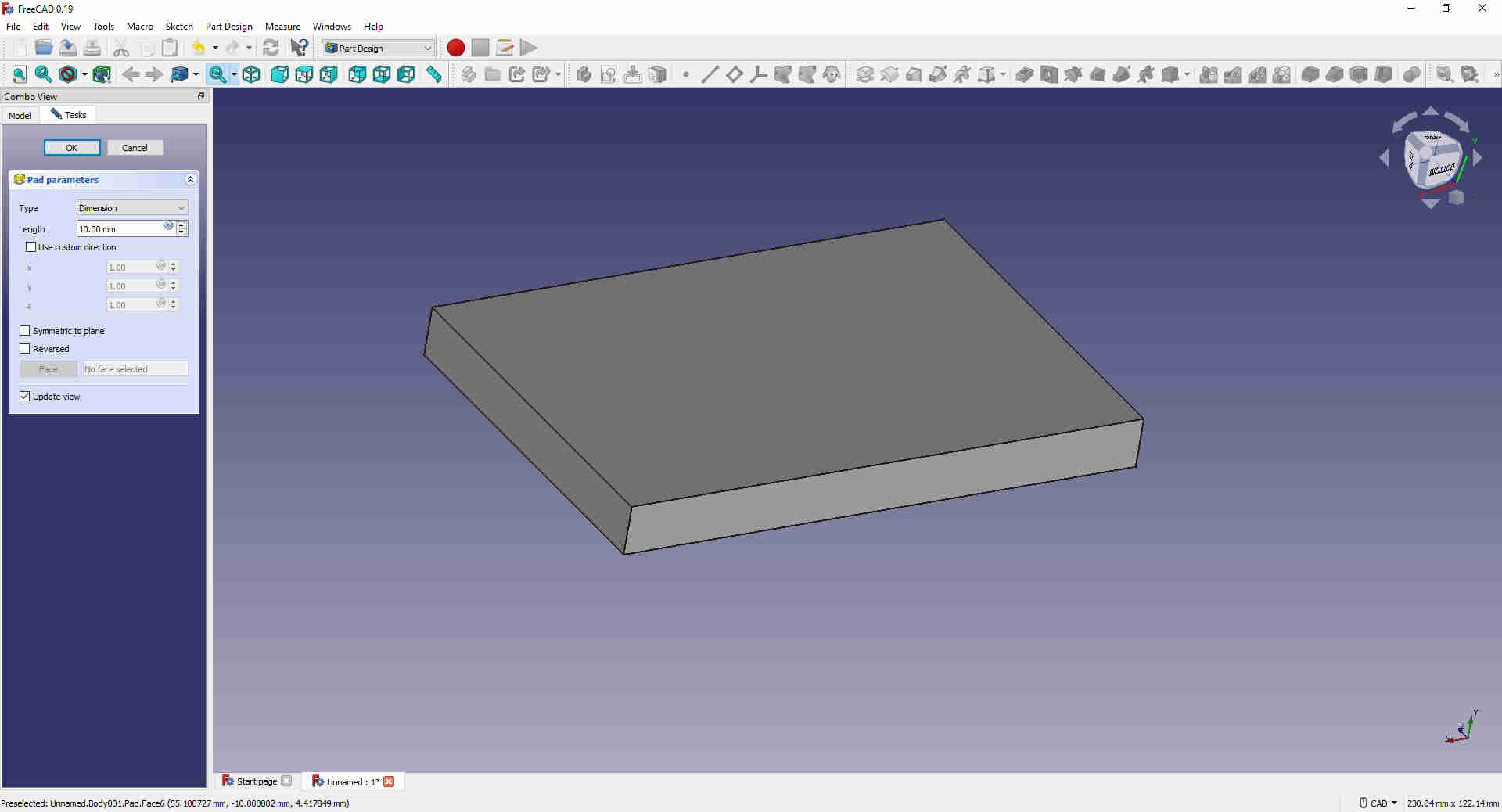
I started my sketch with a rectangle using the rectangle tool.
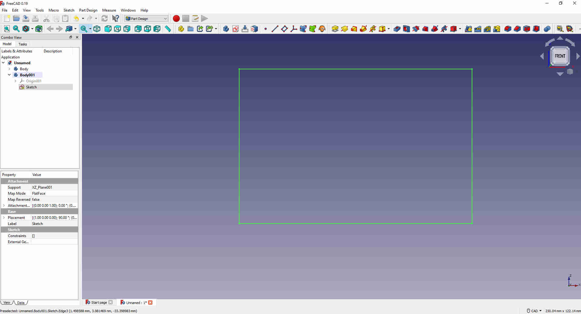
I then added padding to give it some thickness making the object 3D. I gave it a thickness of 60mm.
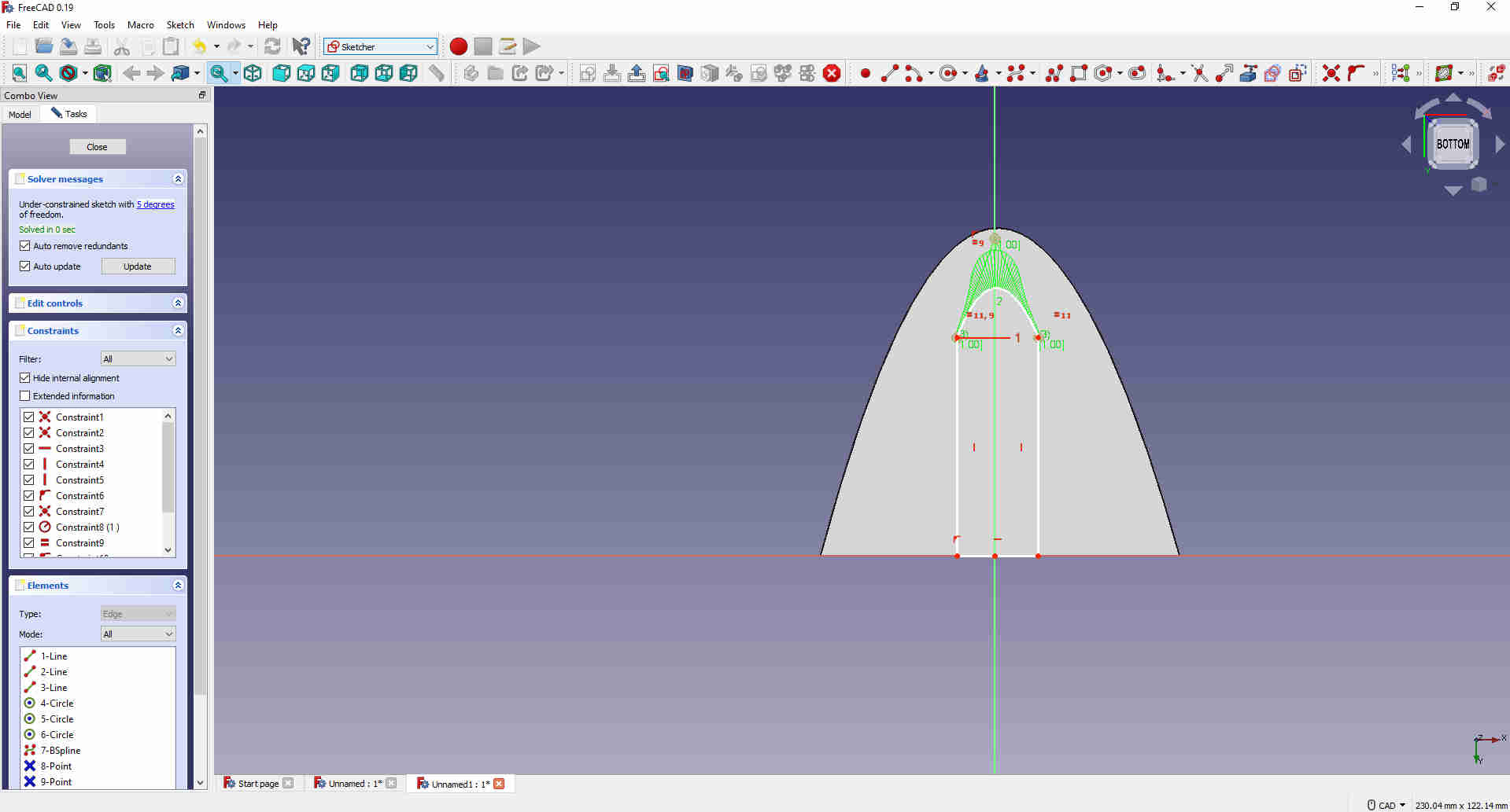
I selected the right side of the box object, selected sketch and used the B-Spline tool to create a shape for cutout.
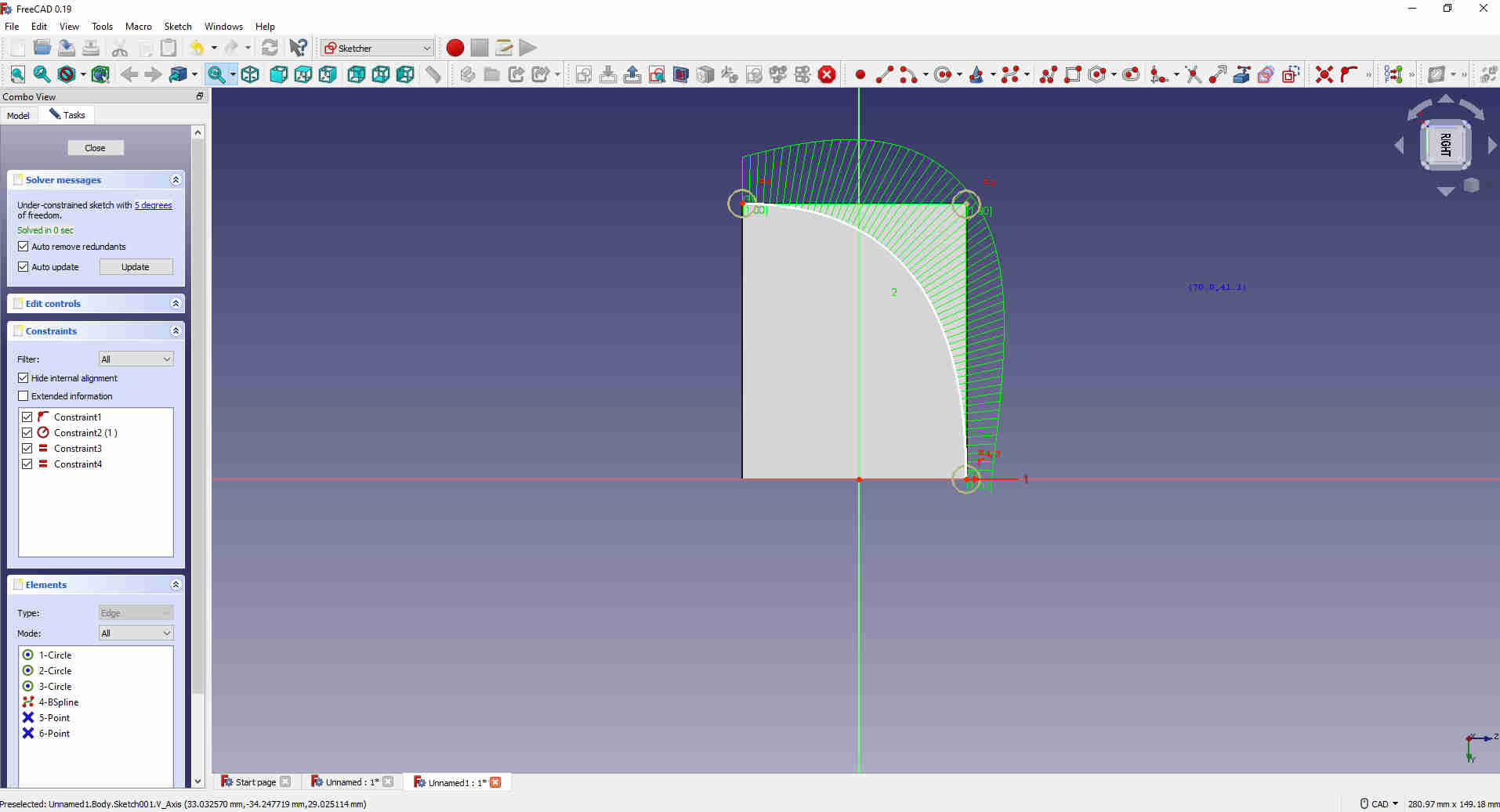
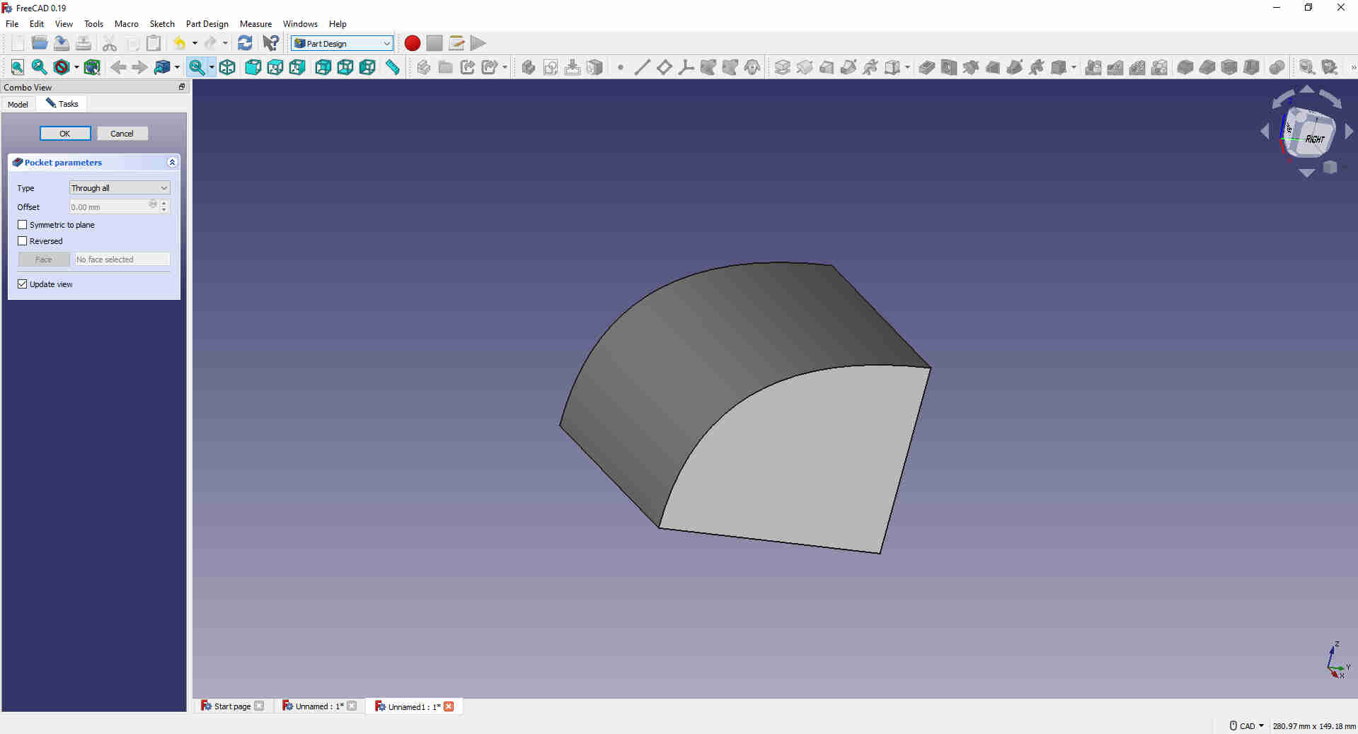
I used the pocket tool but the pic below shows where I went wrong.
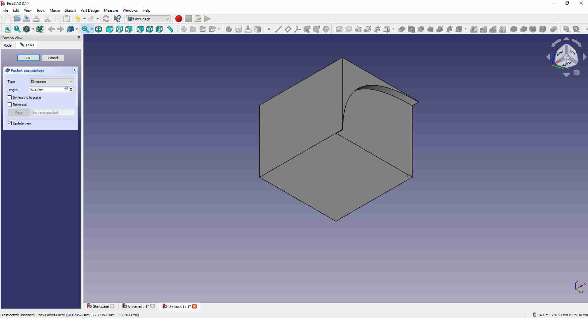
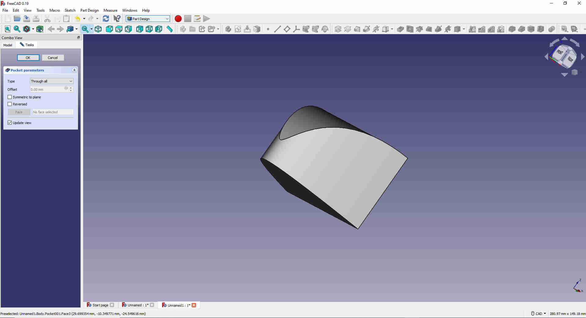
What I had to do was create and outter object so that when I use the pocket tool it will create an inverse pocket.
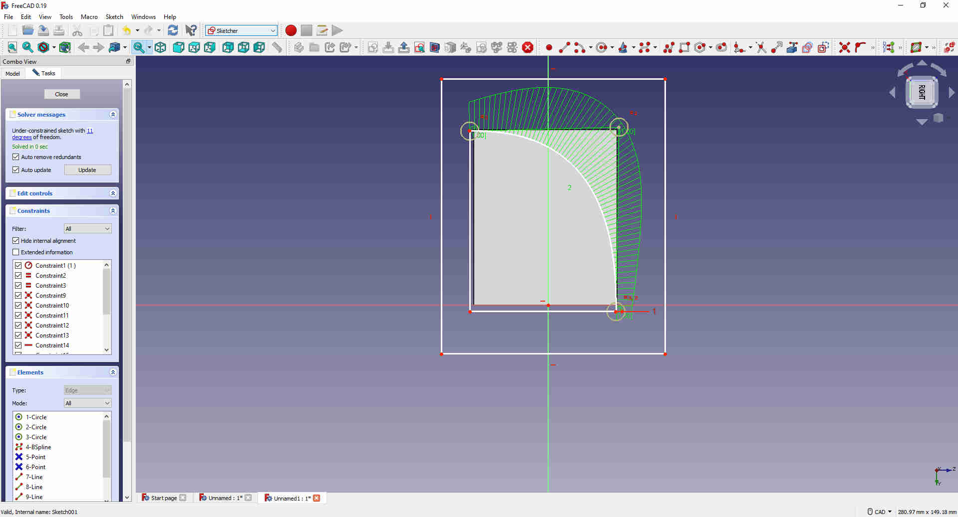
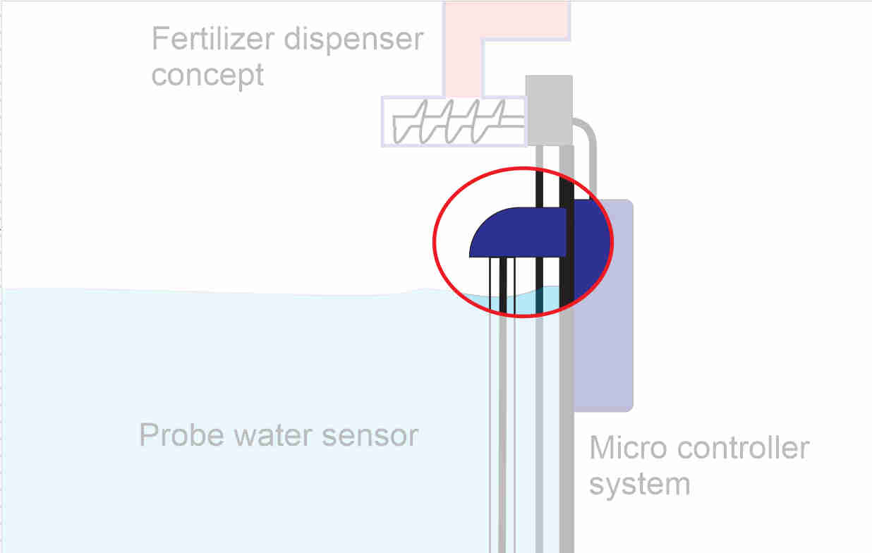
I repeated the steps on the bottom side of the box.
I made a pocket at the bottom and a circular from the back. This is so that my sensor can be bent and pass through this opening to meet and connect directly to the micro-controller board and the other end goes straight into the water.