The assignment for this week was to desisgn and cast a omponent by 3D milling a piece and making a mold to cast with. For my final project, the Thermoelectric Generation (TEG) and electronics cover is too large to print using the 3D printer, therefore I have elected to rotary cast it this week. As usual there is both a group assignment and an individual assignment. Details regarding the assignments for this week are given below.
Group assignment:
For the group assignment, we were asked to:
- Review the safety data sheets for each of your molding and casting materials
- Make and compare test casts with each of them
Individual assignment:
- Design a 3D mould around the stock and tooling that you’ll be using, mill it (rough cut + (at least) three-axis finish cut), and use it to cast parts.
Learning outcomes
- Design appropriate objects within the limitations of 3 axis machining
- Demonstrate workflows used in mould design, construction and casting
- Review the safety data sheets for each of your molding and casting materials, then make and compared test casts with each of them
- Document how you designed your 3D mould and created your rough and finish toolpaths for machining, including machine settings
- Shown how you made your mould and how you cast the parts
- Describe problems and how you fixed them
- Include your design files and ‘hero shot’ of the mould and the final object
Group Assignment
For the Group assignment we looked at the MSDS’s of the materials we planned to use for casting. Below are the links to all of the MSDS’s
Individual Assignment
The objective for the individual assignment was to design a mould and cast it. To do this I elected to cast the TEG and electronics cover that I intend to use for my final project. Doing this required three major steps. I will discuss the workflow for each in the following sections. The three major steps were:
- Design your moulds
- 3D mill your blank
- Cast your negative mould
- Cast your component using your negative mold
This page will be organised into those three sections. Each to be discussed in detail below.
1. Design your moulds
The first step in the casting process is to design and mill your 3D blank. To do this, various steps are involved. Below the workflow that I have used to complete this step:
a) Ensure your piece is millable and castable
b) Convert your 3D model STL/Step file into a solid
c) Put the solid into a block and subtract it to create model the negative
d) Slice your solid in two to create your positives for milling
e) Add a mounting plate with registration marks, material entries, and vents (if applicable)
f) Export your moulds as STL
Details regarding each step are presented below.
Note that a good video that provides an overview of the entire 3D modelling process for molding and casting is the video created by Kris from Aalto Fab. It can be found below:
1a) Ensure your piece is millable and castable
In this step we will ensure that our piece can indeed be milled and casted. Things to consider include the length of the bit, draft angles, and drillbit access. If the piece is not millable as is, we will need to make some changes to our model to ensure that it will be. Below is a list of things I needed to consider:
-
Bit length and Z-travel vs height of piece: The piece that I chose to cast was around 12cm, and our ShopBot has a Z height travel of only about 15 cm. When we consider the need for the bit to be able to clear the cut piece we have a problem (as a rule of thumb your piece cannot be greater than half of the z height travel of the machine). Therefore it will be necessary to cut the piece in half (as shown in the photos below) and mill both halves and add registration marks to glue them together


-
Draft angles for ease of demolding The next thing that needed to be considered for my piece was the addition of draft angles so that it would be possibe to demould my piece after it was cast. Therefore some changes to the sketches has to be made in my model as shown in the photo below

1b) Convert your 3D model STL/Step file into a solid
The next step in the workflow is to convert your 3D model STL file into a solid so that you can perform boolean operations and subtact it from your mold. Below is a short youtube video explaining how to do that.
once complete we will want to take that solid and subtract it from a block in order to create your mold negative (or positive).
1c) Put the solid into a block and subtract it to create the model negative
The next step is to try and create your mold negative (or positive) that you intend to mill. It sometimes helps to first model your mold negative and then subtract it from a block to create your positive. This is easier if you have difficulty thinking in reverse. If that is not a difficulty for you, it is also possible to just create your positive right away.

now that you have an idea of what the negative will look like, you can slice it in half in order to create your positives and dd your registration marks
1d) Slice your solid in two to create your positives for milling
The next step is to now take your negative that you created and subtract to make a positive and slice that in half. this will enable you to add any registration marks and funnels and vents that will be required in the next step.
Now that you have to halves you will want to make registratin marks for your actual mould as shown in the next step.
1e) Add a mounting plate with registration marks, material entries, and vents (if applicable)
In this step you want to ensure that all of the features that you will require to ensure the two halves of your mould match up, that you have a place to pour the material to fill your mould, and that there are appropriate vents in your mould to ensure that all of the cavities will properly fill when you go to pour it.

Once complete, you will then want to export it as an STL.
1f) Export your moulds as STL
Lastly you want to export the positives of your mould for milling as STL and ensure that they are correct.

The next step in the moulding and casting process is to mill your blanks/positives so that you can cast your mould.
2. 3D mill your blank
The next step in the moulding and casting process is to mill your blank. This requires a new skill set of 3D milling which needs to be learned. Before entering into the workflow details, I will first share a video demonstrating how to use a large format CNC machine (ShopBot) for 3D milling. The video can be found here:
Now that we have learned the basics of how to use the ShopBot of for 3D milling I will present the workflow used to complete this step:
a) Create your block for milling
b) Fixture your block to the CNC bed
c) Create your toolpaths (1 roughcut and 2 finishes)
d) Mill your piece
e) Sand and finish
f) Add sealant
Each of these steps will be presented in detail below.
2a) Create your block for milling
The first step is to create your block that you intend to mill your positive cast from. For my project, I elected to use MDF boards that were glued together with woodglue as seen below.


Simply apply wood glue to each piece and clamp them together and allow them to sit overnight.
2b) Fixture your block to the CNC bed
You want to fixture your piece in such a way that the fixturing will not interfere with the milling process. For my project it was elected to use screws that were dug into the sides of the workpiece as a method of fixturing.


once fixtured, you will want to create your tooltpaths
2c) Create your toolpaths (1 roughcut and 2 finishes)
For each piece I created 3 toolpaths: 1 roughcut, and 2 finishes with rastors in the x direction for one, and a rastor in the y direction for the second. The images below illustrate the toolpath settings. Note that for the finishing cuts you want to use a small stepover, and for the roughcut you want to use a large stepover in order to reduce time.

the next step is to mill your piece.
2d) Mill your piece
The next step in the process is to run your CNC and mill your piece. You will want to do as mentioned one rough cut and two finishing cuts. Also note that for 3D CNC milling it is preferable to zero your machine to the top of the cutpiece


Below are some short videos demonstrating the milling process.

Once the milling is complete it is time to move onto sanding and finishing
2e) Sand and finish
Although it is desired, it is not always possible, or time friendly to have a completely smooth finished surface, therefore, it may be necessary to do some minor sanding and finishing to remove some of the roughness. Below some photos of the pieces before and after sanding and finishing.


Also note, that my piece had to be milled as two pieces that were joined together, it was therefore necessary to glue to the top half to the bottom half and sand away the seam as best as possible.
2f) Add sealant
The last step in preparing the positive is to add a sealant and finishing coat to your sanded piece. We used varnish and allowed it to cure over night. Below are some photos


You want to ensure that you cover every surface that will come into contact with your casting material. The next step in the process is to create your negative mould that will be used to cast your final piece.
3. Cast your negative mould
In this step, we will take the blank/positive we created and cast it. Below is the workflow that I used to complete this part of the process.
a) Build the mould walls b) Tape the inside seams to ensure no leakage c) Tape the mould together d) Spray on mould release e) Mix and prepare the mould material f) Pour the mould material e) Allow to set and cure f) Remove the mould walls g) Carefully demould the blank/positive
We will begin the process by building the mould walls
3a) Build the mould walls
For my project, we elected to build the mould walls out of XPS that you can get at the hardware store. We elected to use this materia because it is easy to use, it is low cost, and most importantly, it will not react with or stick to the Oomou casting material that we used. Below are some photos of the construction of the walls.


Next you want to ensure that all the inner seams are taped so there is noleakage.
3b) Tape the inside seams to ensure no leakage
Once the walls have been built, you want to ensure that all of the inner seams are properly sealed using tucktape as shown in the images below:


following this you will want to tape the mould together.
3c) Tape the mould together
Next you want to tape the mold together very well so that there is no chance that it will leak or that it will break. We also elected to add a wood frame on the inside that we would embed within the Oomou so that the mould has some rigidity. Below some photos of that process.


next spray the mould release and prepare to mix.
3d) Spray on mould release
The next step is to spray the mould release onto all of the internal surfaces. The mould release is critical in ensuring that you are able to extract your mould at the end of the process. Be sure to apply it gratuitously to all inner surfaces.


one complete prepare to mix the mould material and pour it.
3e) Mix and prepare the mould material
For the casting of our negative mould, we elected to use Oomou as our mould material. Oomou comes in two parts that are mixed evenly by volume. You must first mix each part, then combine, then mix together. The images below show the process.


Once mixed you can pour the mould
3f) Pour the mould material
You can determine the amount of mould material required to make your negative mould by using the volume of the model you created in step 1c. With that, you can begin pouring.
In order to reduce bubbles it is critical that you paint the first layer onto the mold and push the material into the seams with a brush as best as you can before filling the mould and pouring the rest in.


Next, one the first layer has been painted on and you have given the mixture time to degas and the bubbles to escape, you can now pour the rest of the material to fill the mould. Note, that it is important to pour from a long distance to produce a long thin stream that will not agitate the mixture too much and thus cause air to enter into the mould.


Now go home and have a good night’s sleep while you wait for the mould to cure over the next 12 hours.
3e) Allow to set and cure
This step is pretty self explanatory. Take this time to read through material sheets or work on other aspects of your project, OR BETTER YET, SLEEP, OR GET OUTSIDE. I chose to enjoy the day and get outside.


Once it is set, it is time to get back into the lab and remove the mould.
3f) Remove the mould walls
Now that you have enjoyed some much needed time outside the lab, it is time to remove the mould walls.


the last step is to very carefully demould the blank/positive
3g) Carefully demould the blank/positive
For this step we used screw drivers and pry bars to carefully remove the positive out from the mould. Unfortunately we were very preoccupied with the demoulding process and were unable to get any photos of the process itself. We therefore only have photos of the mould after it was demoulded.


Congratulations! you have now made your negative mould that you can use for casting. Time to move onto the final phase of the moulding and casting process.
4. Cast your component using your negative mould
The final phase of the moulding and casting process is to cast your piece using the negative mould created in the phase prior. For my project, I elected to use the rotary casting machine that I built in the machine building week so that I can make the piece required for my final project. To do this I have developed the following rotary casting workflow.
Rotary Casting workflow
a) Determine centre of mass of mould
b) Mount mold in machine
c) Check the balance
d) Leak test
e) Determine the volume of material required
f) Put material into mold
g) Start machine (machine settings discussion)
h) Extract and finish piece
4a) Determine centre of mass of mold
In rotary casting, it is important that the center of mass of your mould be as close to the center of your machine as possible. It is therefore important that you determine the centre of mass. I did this by balancing the mould on a piece of wood and drawing the balance point on that axis. I then connected dots with lines that show the planes of centre of mass.


Next you will want to mount the mould to the machine.
4b) Mount mold in machine
In this step, you will want to build the mould mounts. You will also want to ensure that the mould is centered in the mounts by its CENTRE OF MASS.


next, you want to check the balance of the mould.
4c) Check the balance
Once the mould is mounted onto the machine, you will want to test the balance by turning the mould vertical on one of its axes and seeing whether it stays put or whether it moves. In the video I demonstrate this process by showing how the mould is unbalanced when the MDF lid is not on and how it is balanced once the lid/cover is installed.
Once completed you will want to do a leak test.
4d) Leak test
To do a leak test, we poured water into the mould, closed it, and then turned it upside down to see if any water came out. We also turned the machine on to see if any leaks could be detected while the machine was rotating.


Once you are certain that the mould will not leak and that cover is sufficient it is time to determine the amount of material required.
4e) Determine the volume of material required
You can determine the amount of material required by using FreeCAD, or whatever modelling software you are using, to calculate the surface area and multiply it by the thickness desired. Below is an instructional video on how to determine the surface area in FreeCAD.
Using the methodology above it was calculated that the volume required was around 300 000 mm3 which is 300 mL. This was done assuming a desired thickness of 2 mm.

Now that you have calculated the amount of material needed (this is important for rotary casting) you can mix it and put it into the mould.
4f) Put material into mold
The material we used was a 2-part liquid plastic mixture that again required equal parts by volume. Similar to last time, you mix them together and then pour them into the mould and the install the cover plate.


Before you do this it is important that you have all the correct setting and are ready to start the machine because the bucket life of the casting material was only 7 minutes. Therefore it was essential that this step be done expediently.
4g) Start machine (machine settings discussion)
You are now ready to start the machine. Be sure to program it BEFORE mixing and putting your material into the mould and then click start. To control the machine we used Universal Gcode Sender
We ran the machine for 1 hour as that was the amount of time required to set it.
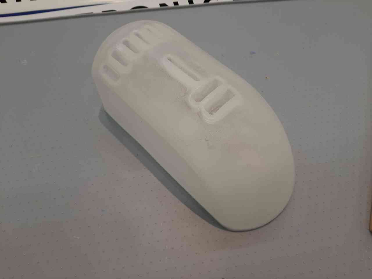
4h) Extract and finish piece
Lastly, remove the piece from the mould very carefully.
Next, remove it from the cover plate and use the dremmel to remove any excess material.


Below is a video of the final result. Note that I was a little careless with the dremmel and ruined the interior finish which affected the overall appearance.
Lastly, some photos.

