The assignment to be completed over two weeks was to build a machine that had a mechanical and electronic component that could be actuated and automated to perform a certain task. This week I worked with my lab instructor Jason to build a rotary casting and photogrammetry machine. The assignment details and learning outcomes are given below.
Mechanical Design (part 1 of 2)
Group assignment:
- Design a machine that includes mechanism + actuation + automation
- Build the mechanical parts and operate it manually.
- Document the group project
Individual assignment:
- Document your individual contribution.
Machine Design (part 2 of 2)
Group assignment:
- Actuate and automate your machine.
- Document the group project
Individual assignment:
- Document your individual contribution.
Learning outcomes
- Work and communicate effectively in a team and independently
- Design, plan and build a system
- Analyse and solve technical problems
- Recognise opportunities for improvements in the design
Have you answered these questions?
- Documented the machine building process to the group page
- Documented your individual contribution to this project on your own website
- Linked to the group page from your individual page as well as from group page to your individual pages
- Shown how your team planned and executed the project (Group page)
- Described problems and how the team solved them (Group page)
- Listed future development opportunities for this project (Group page)
- Included your design files (Group page)
- Optionally included an aprox. 1 min video (1920x1080 HTML5 MP4) + slide (1920x1080 PNG) (Group page)
The Machine
In this section, I will describe the idea behind the machine, why it was built, and show a video that demonstrates the final product in action. I wil begin by first describing the idea.
Description of the idea
During the 3D printing and scanning week, it was discovered that, the piece that I intended to print for my final project is too large for our 3D printer beds. After some brainstorming, Jason came up with the idea of using rotary casting to create the part for my final project.
Furthermore, during the 3D scanning exercise, we found that the results of our photogrammetry and lidar scanning left something to be desired.
Moreover, we had been brainstorming about possible ideas for the machine building week, in which we wanted to build something that could be useful to the lab. Cue the photogrammetry caster a dual purpose machine that can be used in either a 3D scanning, or rotational casting configuration.
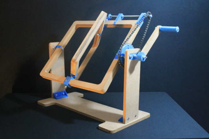
In essence, our idea was to combine a rotational casting type of design such as the one below:
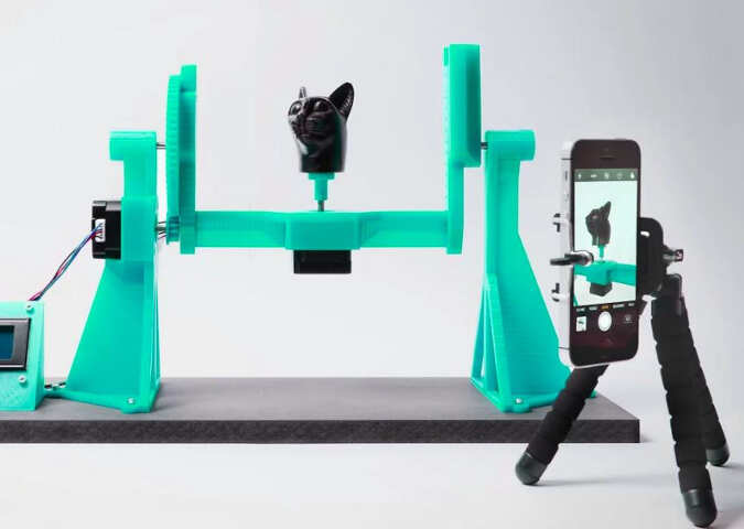
with the open source 3D scanning software and machine controller available at OpenScan as shown in the image below.
The idea is, over the following weeks, to build one modifiable machine that can be switched from rotary casting mode to 3D scanning mode with minimal modifications.
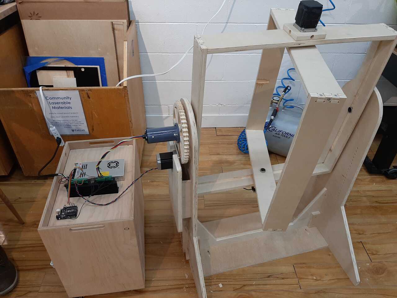
The result
In order to save a bunch of scrolling, I opted to include a video of the machine in operation here. In this video, you can see the machine being used in its rotary casting mode using a gcode program to control the machine. As can be seen the machine rotates on two axes and with one axis being geared down at a ratio of 8:1 and the other axis being directly driven by the motor. The video of the machine in operation is shown below.
In the following section, I will go into details to document how the machine was built and the workflow used to build it. Note that workflow for cutting the frame using CNC is shared in week 8. Computer controlled machining
The workflow
In this section, I will discuss the workflow that seemed to work best for me in designing, cutting, building, wiring, and testing the machine. I will also share which parts of the project were designed and built by me, and which were designed and built by Jason. I found the the following steps worked best for me:
- Sketch your concept
- Design your parameterized parts using FreeCad
- Create testfit pieces for joints
- Update your FreeCad files to reflect joint geometries
- Export your files into the appropriate format for the machine used
- Make your pieces
- Assemble and test your mechanical
- Wire the electrical
- Program your circuit board
- Test your machine
I will walk through each step in detail below.
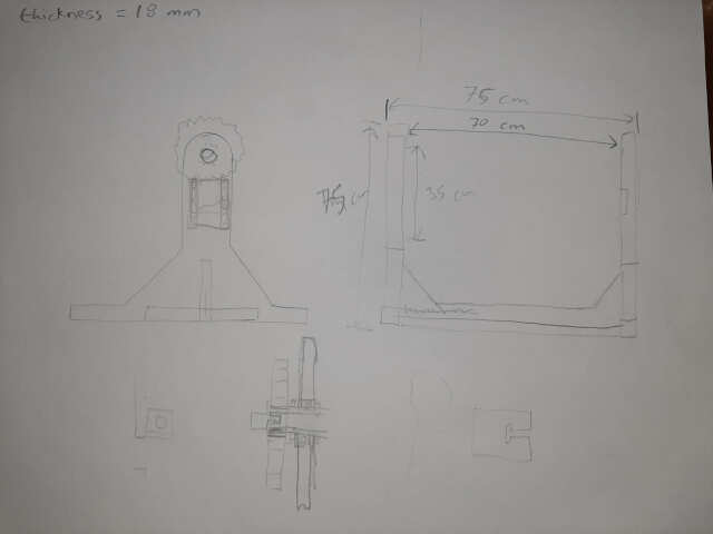
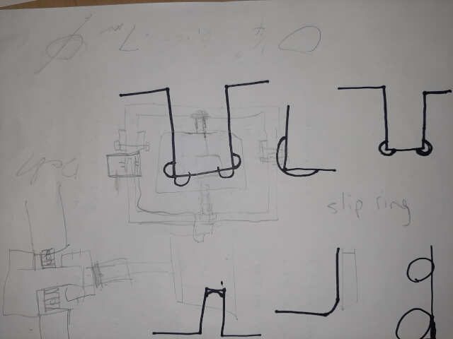
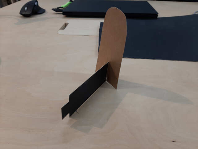
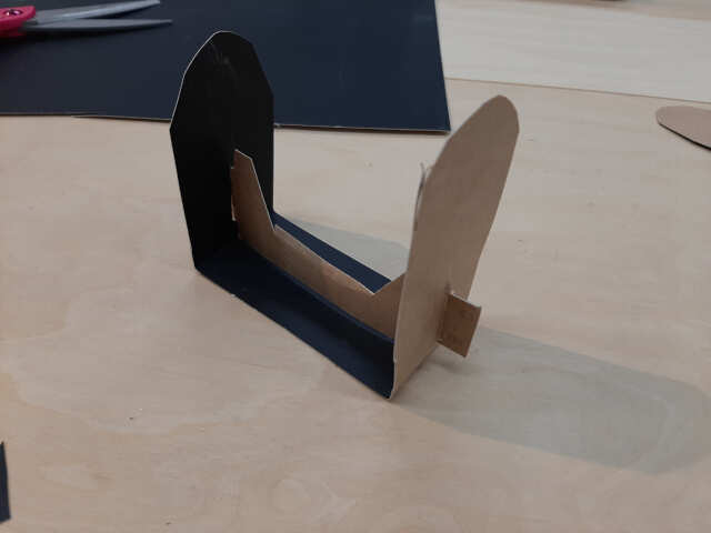
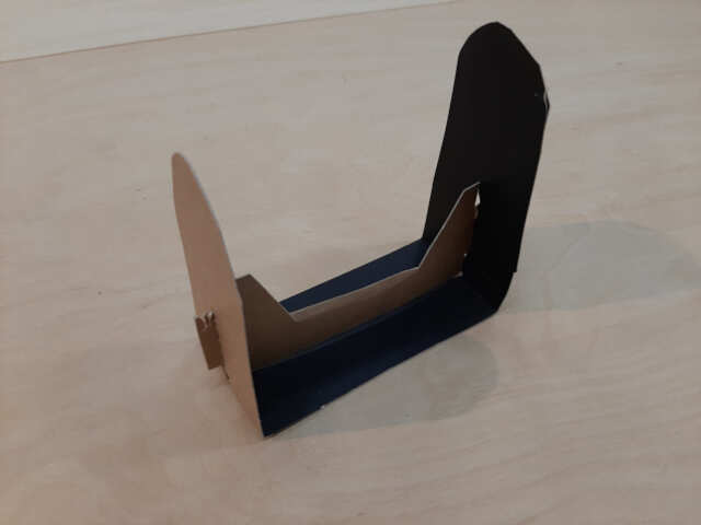
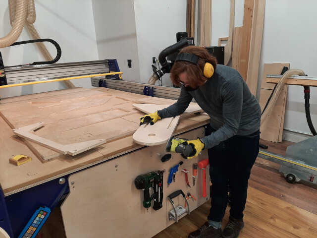
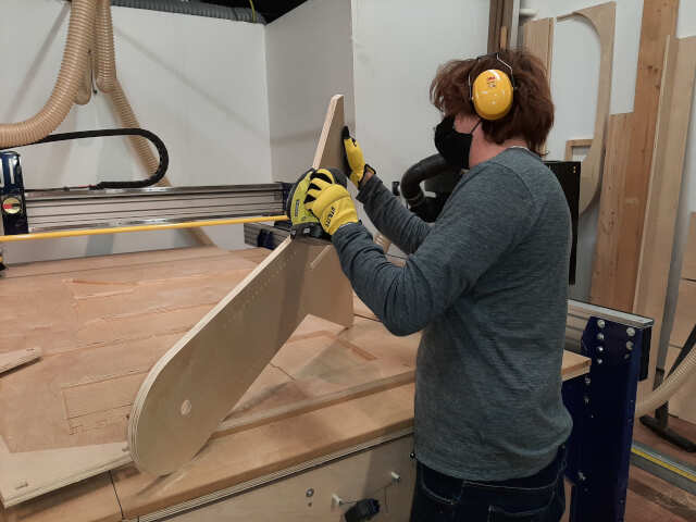
1. Sketch your concept
In this step, develop the concept using pencil and paper and if necessary some construction paper or cardboard to make a wireframe to visualize your joints. The idea is not to make something perfect, but to have some parts concepts to discuss and iterate on. The photos below illustrate the results:

2. Design your parameterized part using FreeCad
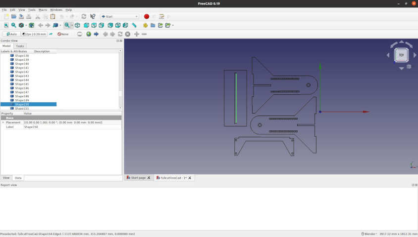
The next step is to take your sketches and wireframes and design a more detailed version of your desgin using FreeCad. For lessons on FreeCad you can revisit Assignment 3.
The results of the FreeCad are shown in the images below:
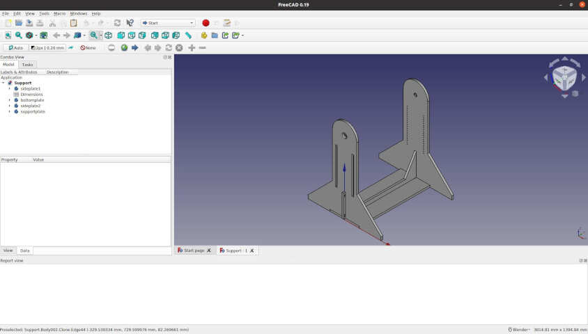
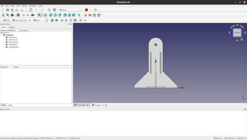
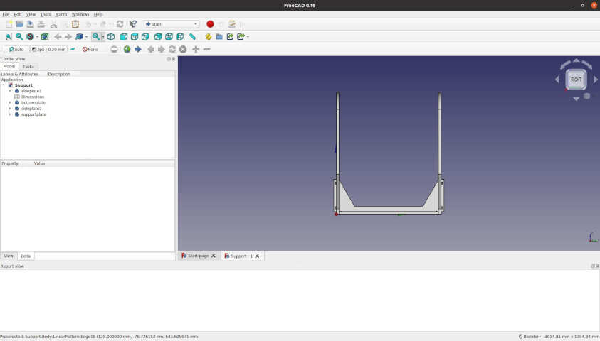
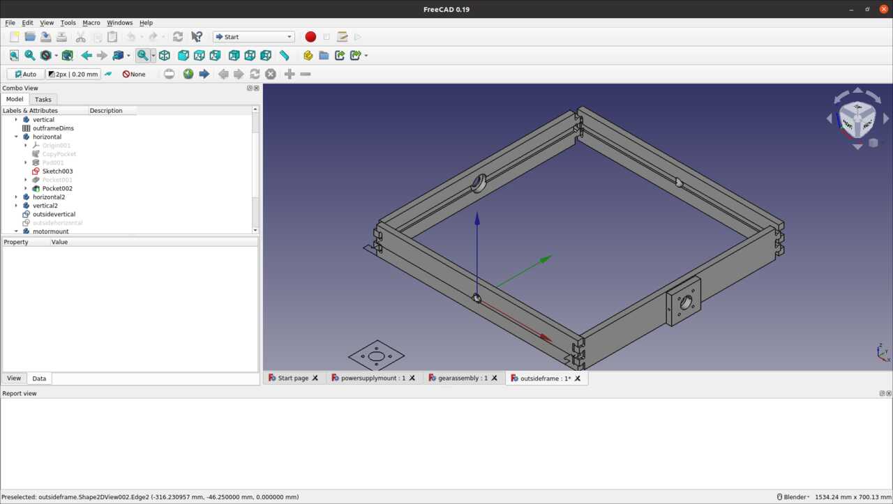
Note, it is extremely important to parameterize your design so that you can change variables such as the material thickness based on the test fits as shown below. The photo below shows the FreeCad spreadsheet that was created for this assembly.

Note that the types of joints used for this design are as follows:
- finger joint
- wedge joint
- tongue and groove joint
The type of cut used for each joint was the t-bone cut. Photos of the final joints will be shown below.
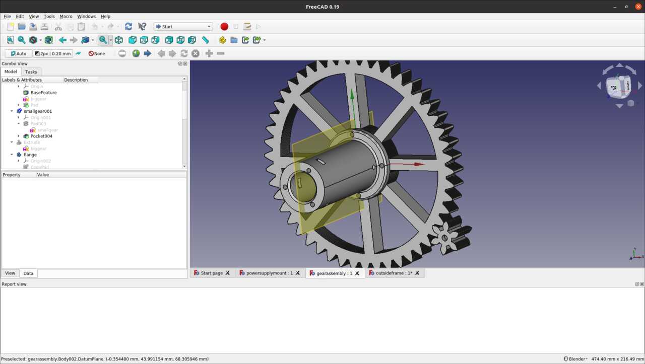
Gear design
A note on the gear design. The gear ratio was calculated by considering the stall torque of the stepper motor and the Torque created by the mold that needs to be casted. Below are the calculations. Note it was assumed that the largest torque would be applied by the 1kg motor at a distance of 50 cm from the center.
Calculated torque requirements:
2 kg at 0.5 = roughly 10 N-m of torque required
Torque of the motor is 1.9 N-m, a gear ratio of 8:1 will give us a torque ratio of roughly 15.2 N-m
We then used the gear ratio we calculated to design the gears using geargenerator.com with the following video shown as a result. Using that we exported the DXF and then imported those into FreeCAD to model and build the gears.
In the next step we will discuss creating test pieces to adjust any paramterized FreeCAD files.
3. Create test fit pieces for joints
The next step is to characterise the machine and the bit you intend to use by cutting a test piece to determine the design material thickness of the joint vs. the cut thickness. This was done during the group assignment with the results shown below:
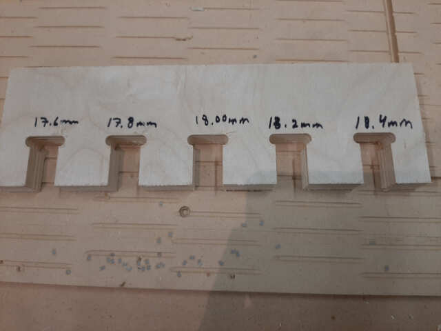
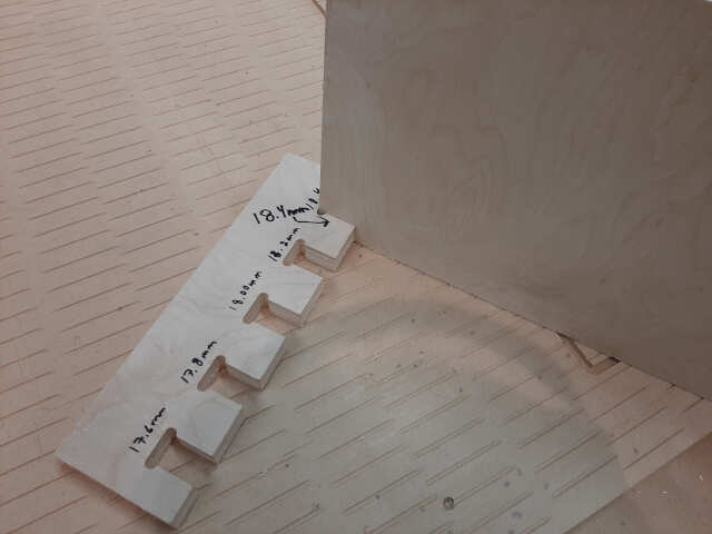
Note that the test piece results resulted in a material thickness required of 18.4 mm
4. Update FreeCad files to reflect joint geometries
In this step, you will revisit the paramaterised FreeCad file created and update the spreadsheet to reflect the results of your test fit. For me, I had to change thickness to 18.4 mm as pictured below
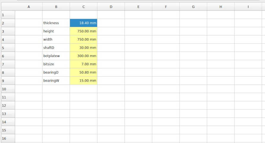
this was repeated for all of the various files.
5. Export your files into the appropriate format for the machine used
The next step is to export your files into the appropriate format for the machine that you will be using. For this project I used DXF files for the ShopBotCNC, SVG files for the desktop CNC, and STL files for the 3D printer.
DXF files for ShopBot CNC
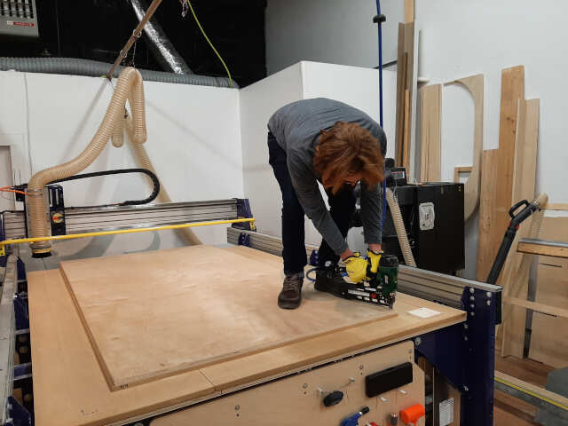
All of the woodframe components were cut out of 18 mm plywood using the Shopbot CNC. In order to use the large format Shopbot CNC, I had to conver the FreeCad files to dxf. There are numerous ways to do this, which I have included in the assignment 8. Commputer controlled machining page. The photos below illustrate the results
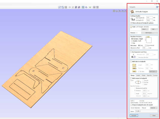
The following images illustrate the resulting toolpaths:
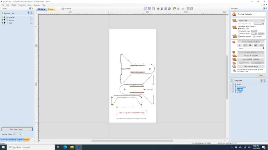
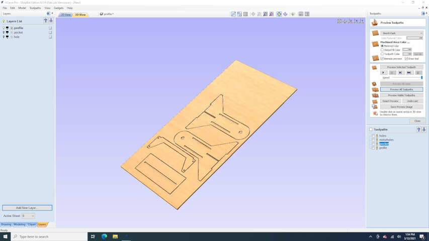
in the next section I will discuss the files used for the desktop CNC
SVG files for desktop CNC
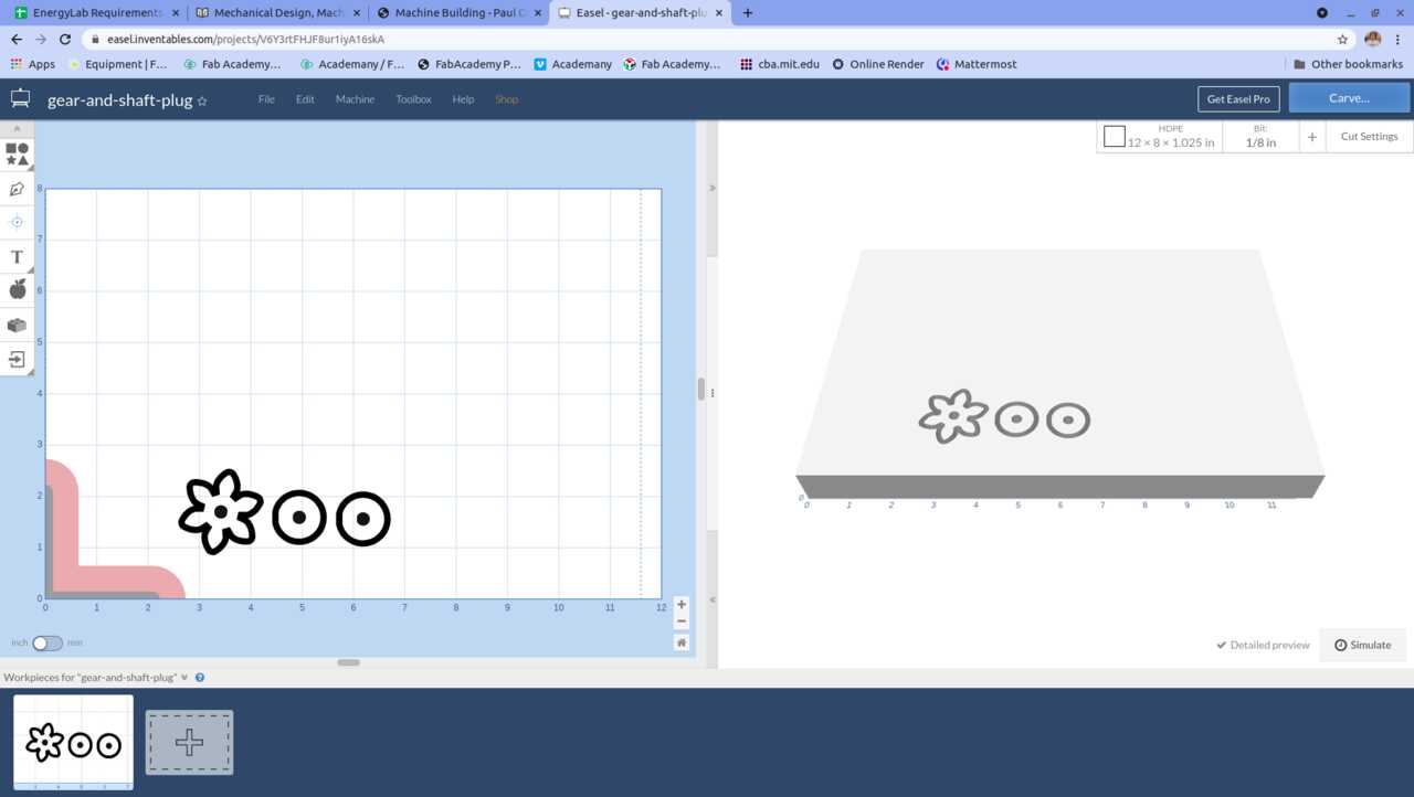
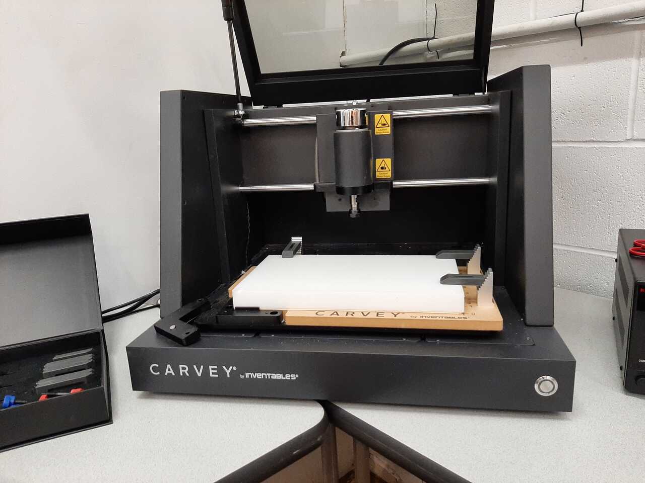
The small gear and shaft plugs to connect the tube to the motor shafts were both milled from 1 inch HDPE using the desktop CNC. To cut them, it was necessary to export them from FreeCAD and convert them to SVG. The methodology used to do this is similar to exporting a dxf and requires some touchups in inkscape as shown in assignment 8. The following photos illustrate the svg files that were generated.
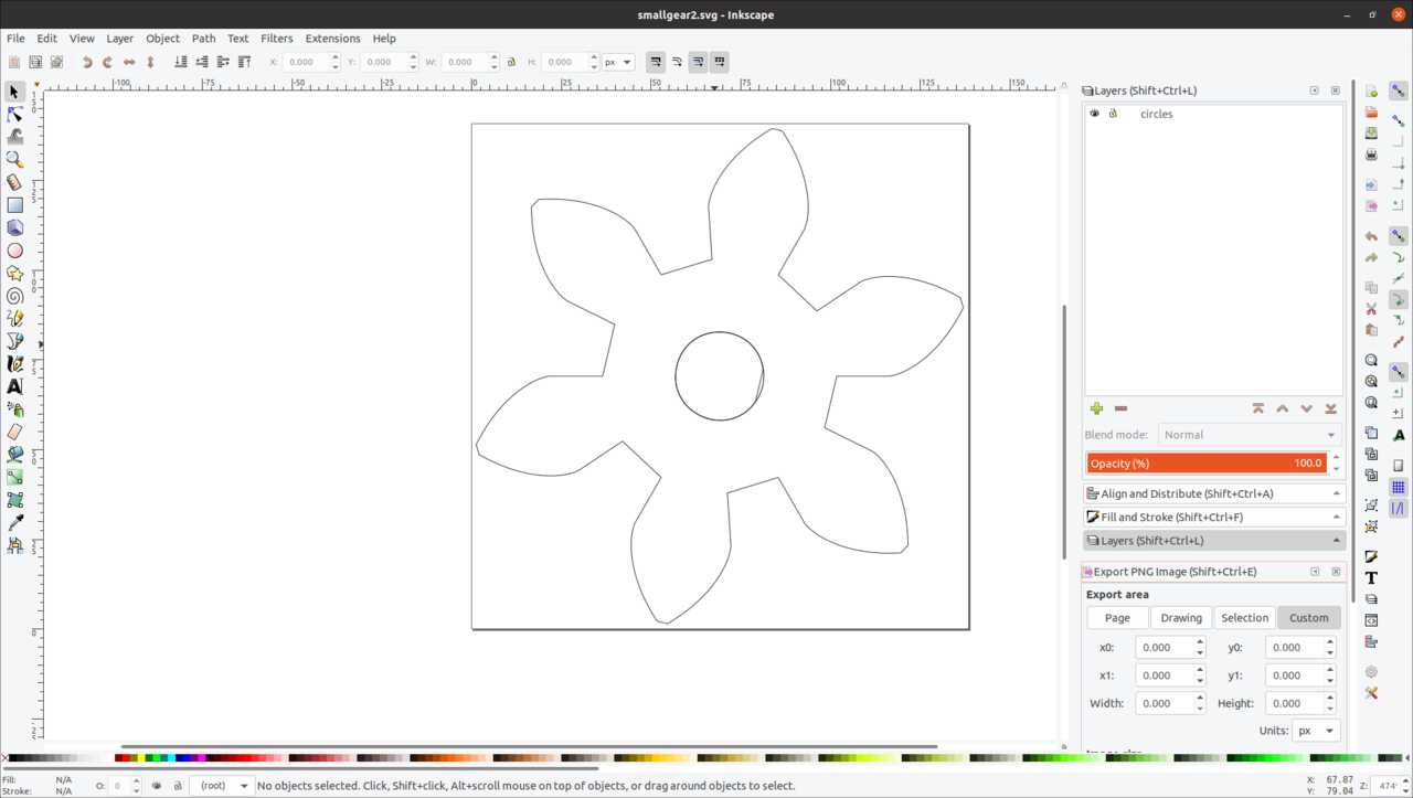
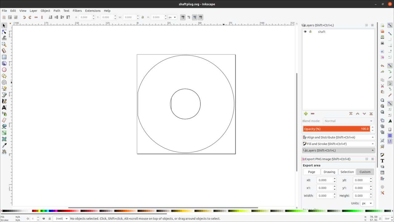
These images illustrate the SVG’s as uploaded to the Easel program that is used to control the desktop CNC.
in the final section of this step I will discuss the files used for the 3D printing.
STL files for 3D printer
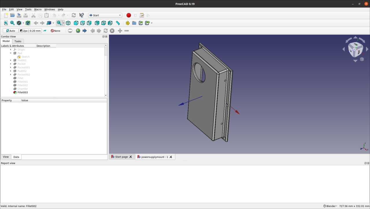
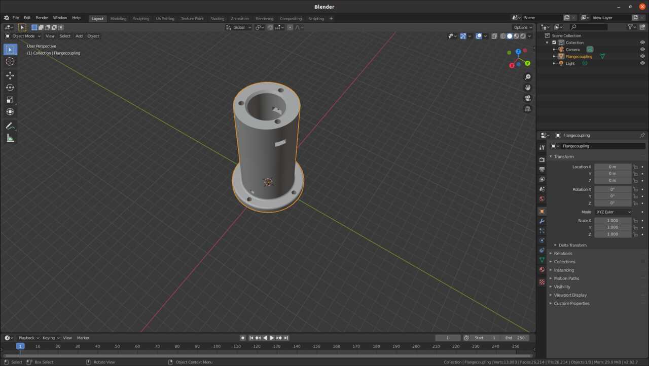
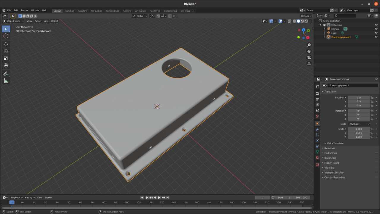
The powersupply cover and rotary coupler were both 3D printed for this assignment. To do this we had to export the components made in FreeCAD to STL. The details on how to do that are given in assignment 6. 3D printing and scanning. The resulting STL files are shown below.
Once all the parts were exported into their appropriate formats for construction it was time to go ahead and create them.
6. Make your pieces
The next step in the worflow use to put your robots to work and get them making your pieces. For this project I used 3 machines: the large fromat CNC, the desktop CNC, and the 3D printer. In the following sections I will list which components were made using which machines and provide photos of the process. Please note that the sections will be broken up by machine.
Large format CNC (ShopBOT)
The large format CNC machine was used to make the majority of the frame and wooden components. Bellow is a list of the components that were made using the large format CNC
- Support side plates x 2
- Support base plate x 1
- Support support plate x 1
- Outter frame vertical bar x 2
- Outter frame horizontal bar x 2
- Outter frame motor mount x 2
- Inner frame vertical bar x 2
- Inner frame horizontal bar x 2
- 64 tooth gear x 1
- Motor box top x 1
- Motor box sides x 2
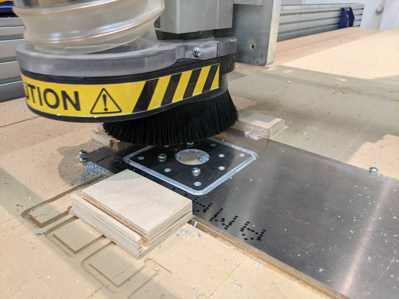
- Motor mounting plate (aluminum) x 1
Below are some photos of the CNC workflow. Details of which are covered in the Assignment 8.
Mounting the board and sanding the pieces
The other machines that were used to created the parts are discussed in the next sections.
Desktop CNC
The desktop CNC was used to make the small gear and the shaft plugs. They were both milled out of HDPE because we wanted them to be more finely machined and much more rigid and strong than any wooden component would be capable of managing. Here is the list in bullet form.
- Small gear x 1
- Shaft plug x 2
Below are some photos of the construction process and end results.
the last thing to discuss in the creation of pieces will be the 3D printing of the components
3D printers
The 3D printers were used to make the gear flange to hold the wire coupler and the power source cover/mount. The purpose of the flange was to attache the wooden gear to the shaft and to connect the slipring which allows current to pass through the rotating shaft to the motor that is mounted on the outerframe. The video below shows the part as it was being printed. Here is the list of components in bullet form:
- Gear flange and slipdisk coupler x 1
- Powersource cover x 1
The next step in the work flow was to assemble all of the components together to make the machine.
7. Assemble and test your mechanical
The next step in the machine building process is to take all of the components that you have just finished making and begin to assemble them to complete the mechanical design of your machine. I will present the photos and steps taken in this process for my machine by breaking the design into the following sub-assemblies:
- Support
- Frames
- Shafts and bearings
- Motor mounts and gears
We will begin with the assembly of the supports
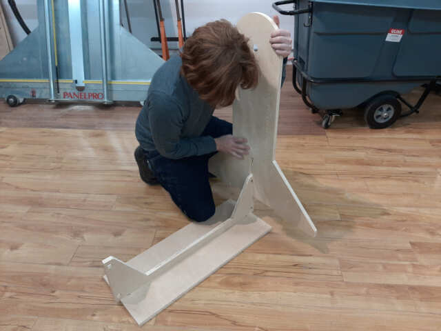
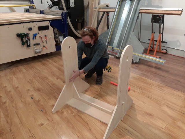
Assembly of supports
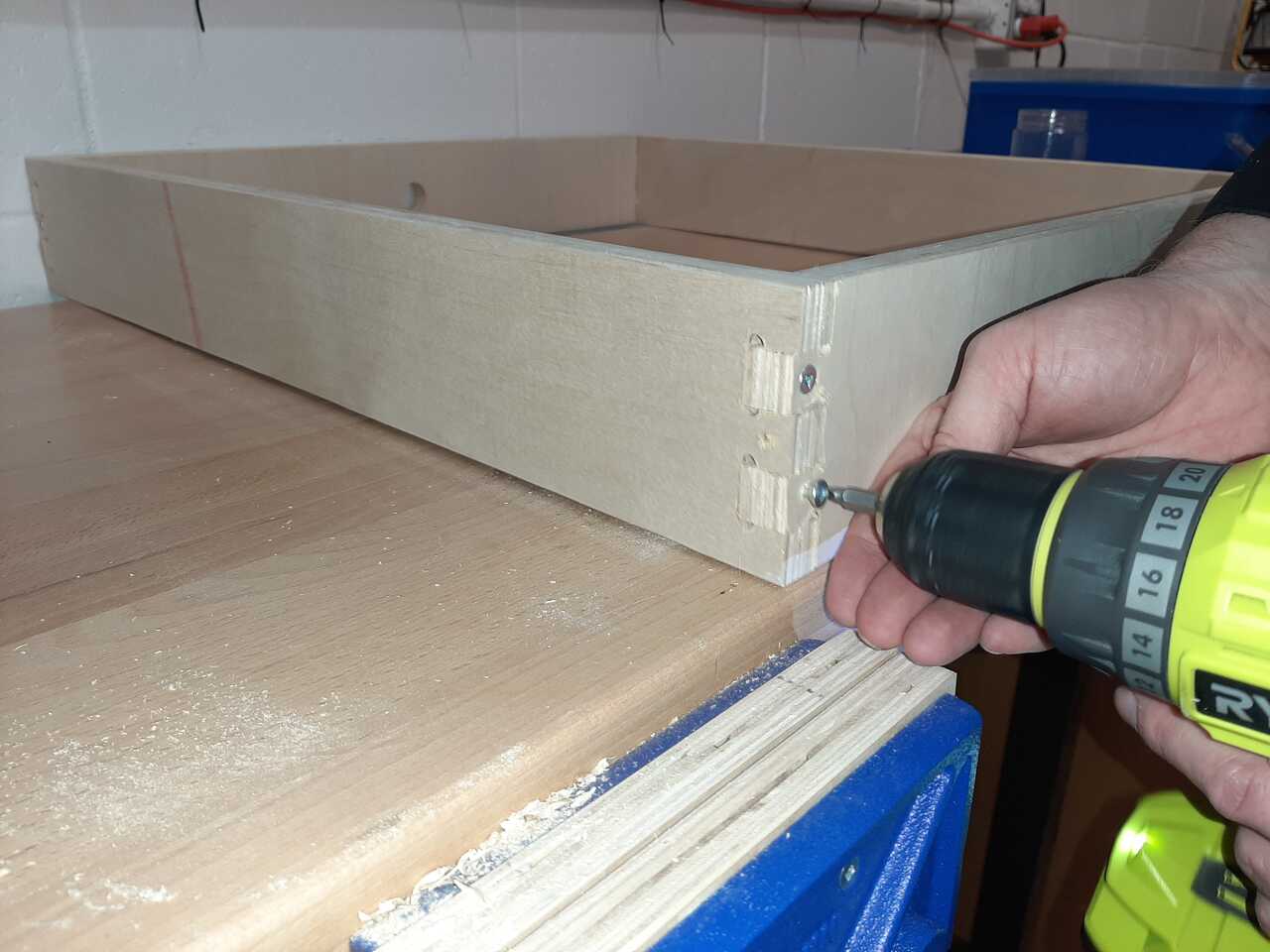
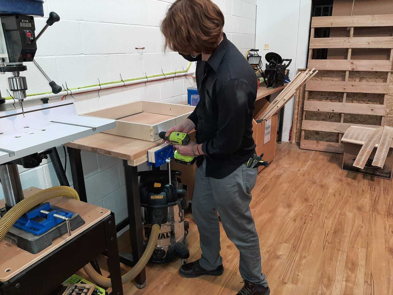
The first step was to assemble the supports. They were joined using finger joints and wedge joints and then secured using screws.
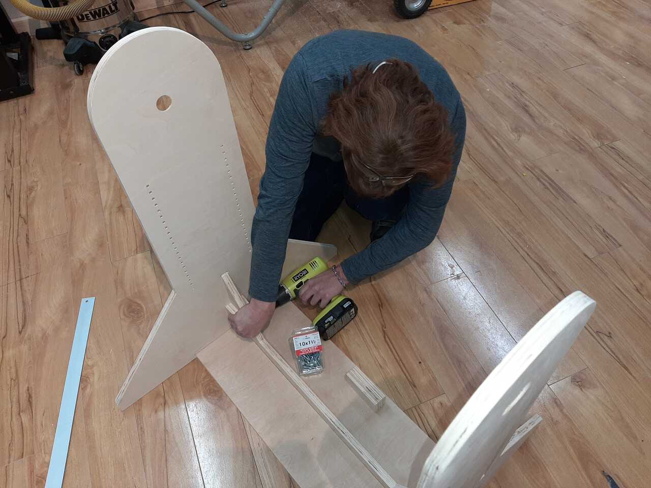
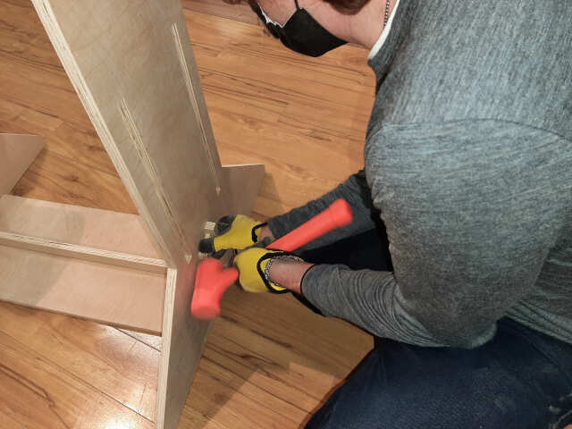
the next sub-assembly that was constructed were the frames.
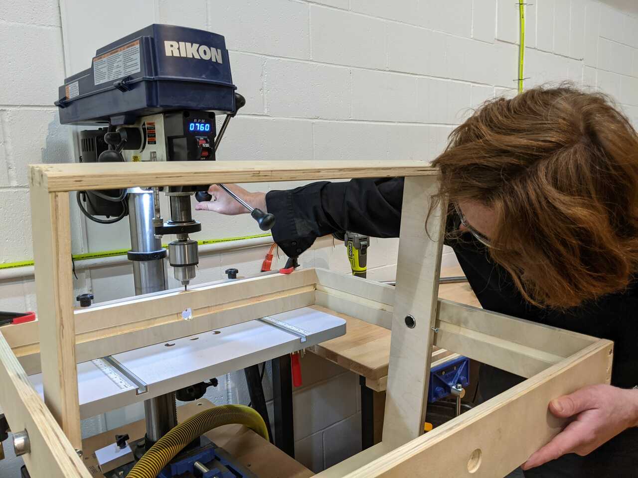
Assembly of the frames
the frames are the elements that rotate. There is an inner frame and an outer frame. The outerframe must be easily dissassembled in order to convert from the rotary casting mode to the photogrammetry mode. The frames were joined using finger joints and screws. Note some sanding was required to get the finger joints to fit properly.
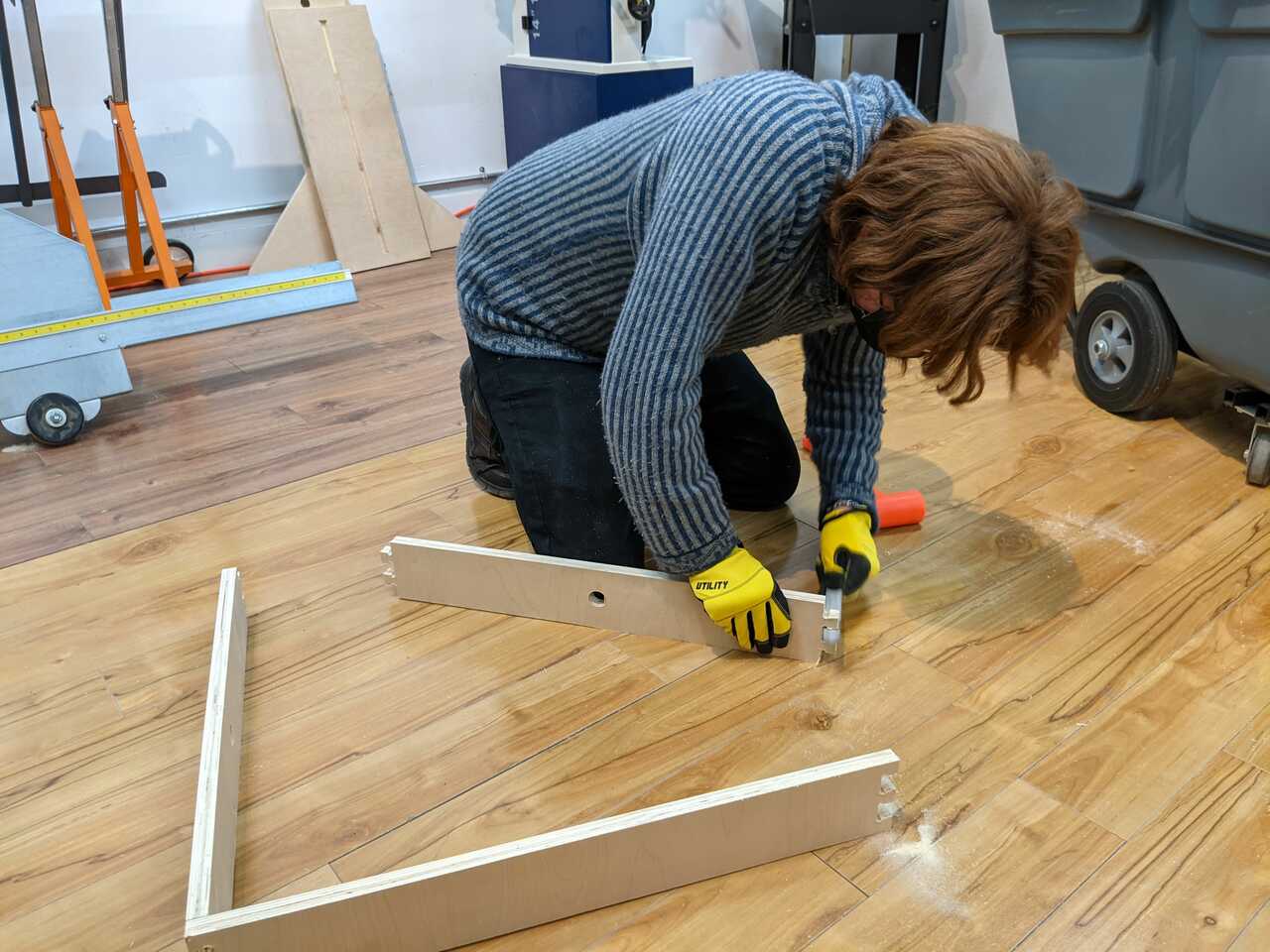
the following assembly was the assembly of shafts and bearings.
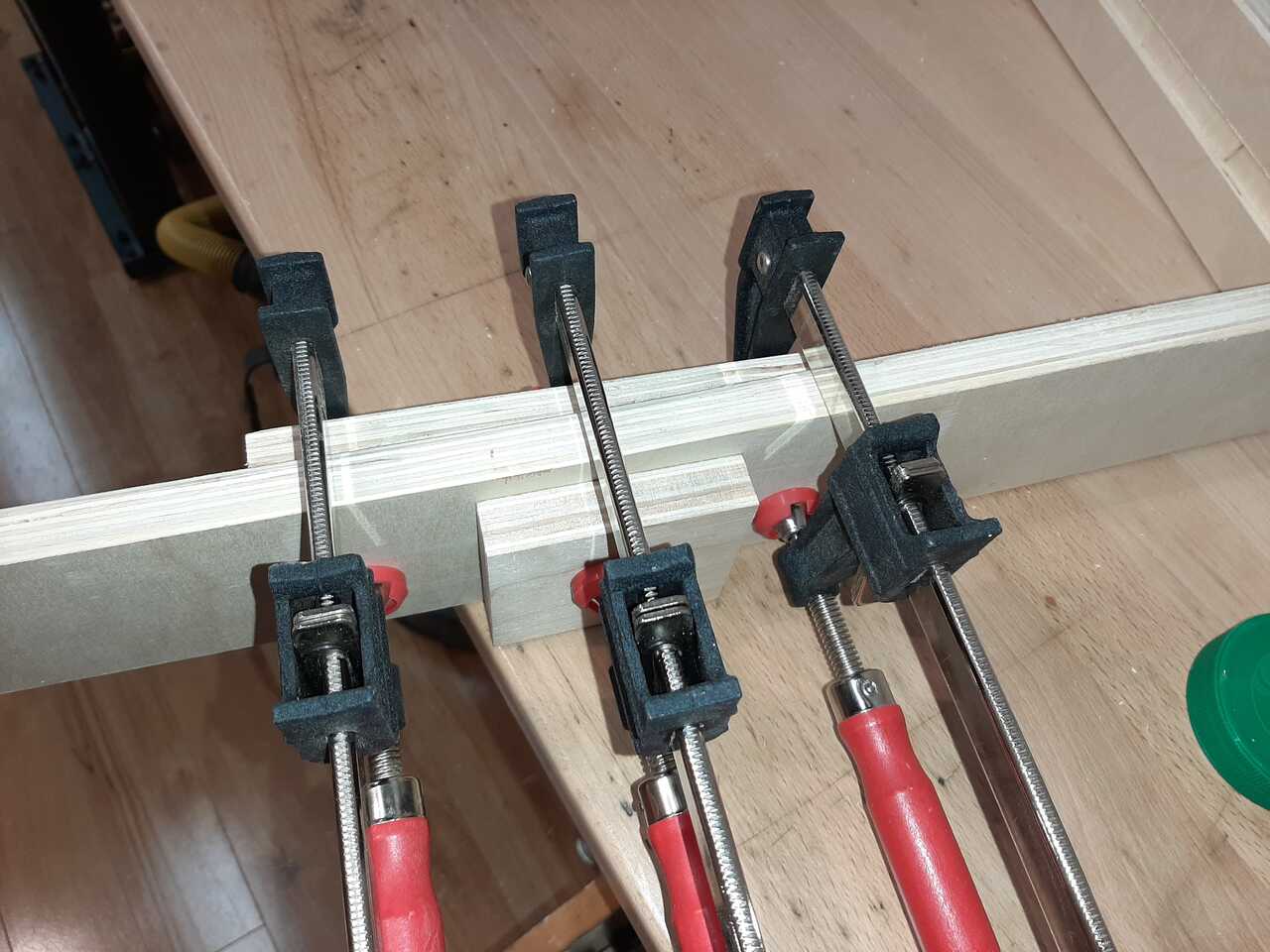
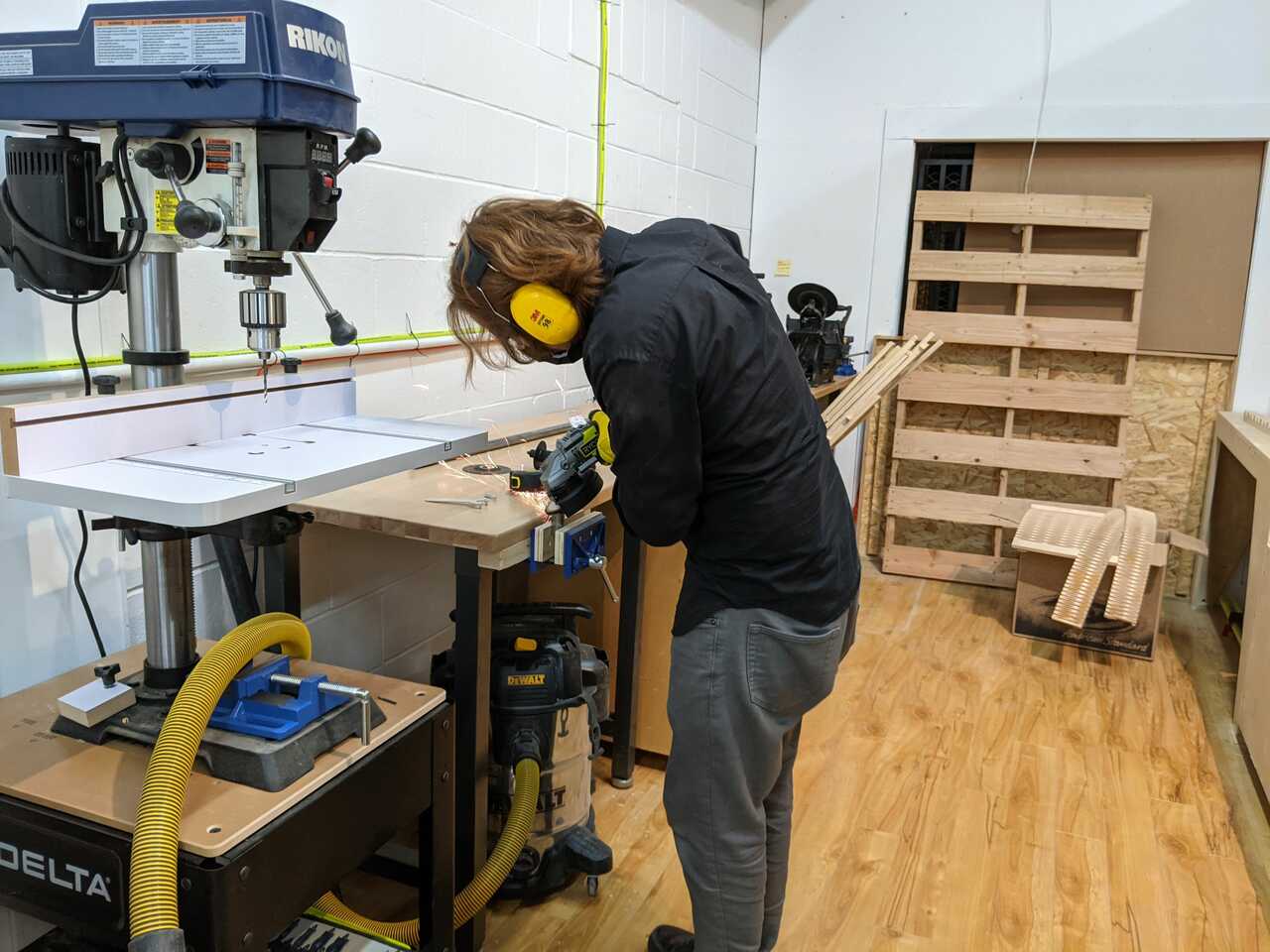
Shafts and bearings
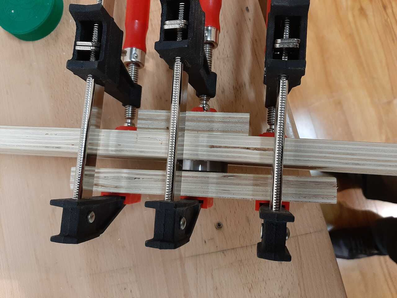
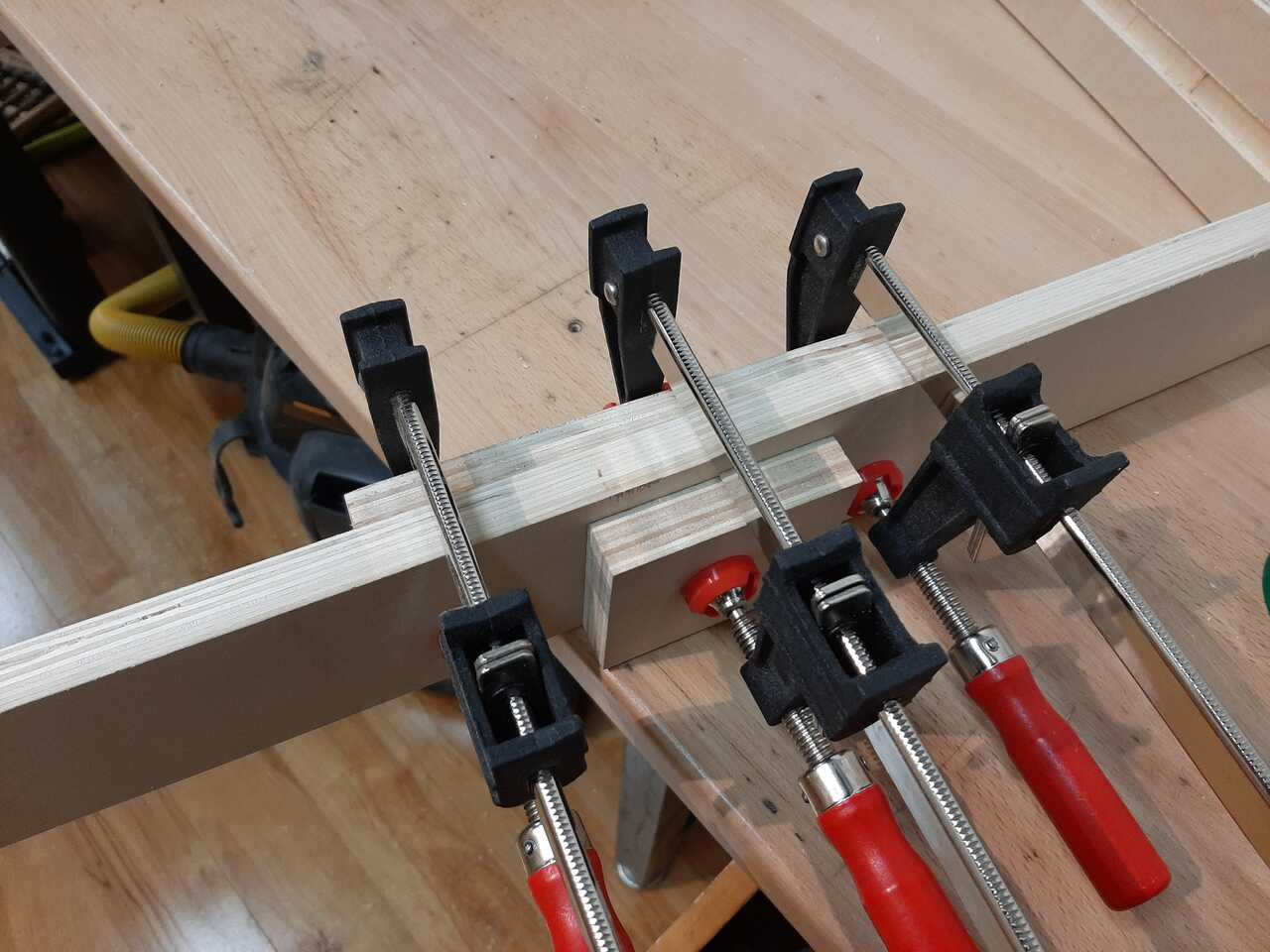
The next step in the assemly was to assemble the shats and bearings. The bearings were pressed into their pockets using clamps and the shafts were cut using a jigsaw and then tapered using a grinder and hammered into the bearings. The following photos illustrate the shaft and bearing assembly.
bearing force fit
shaft tapering and inserting
once the bearings and shafts were all in place it was time to test if it worked.
once we knew the shafts and bearings were all aligned and the clearances were all okay we moved onto motor mounts.
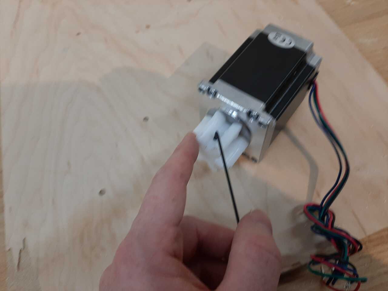
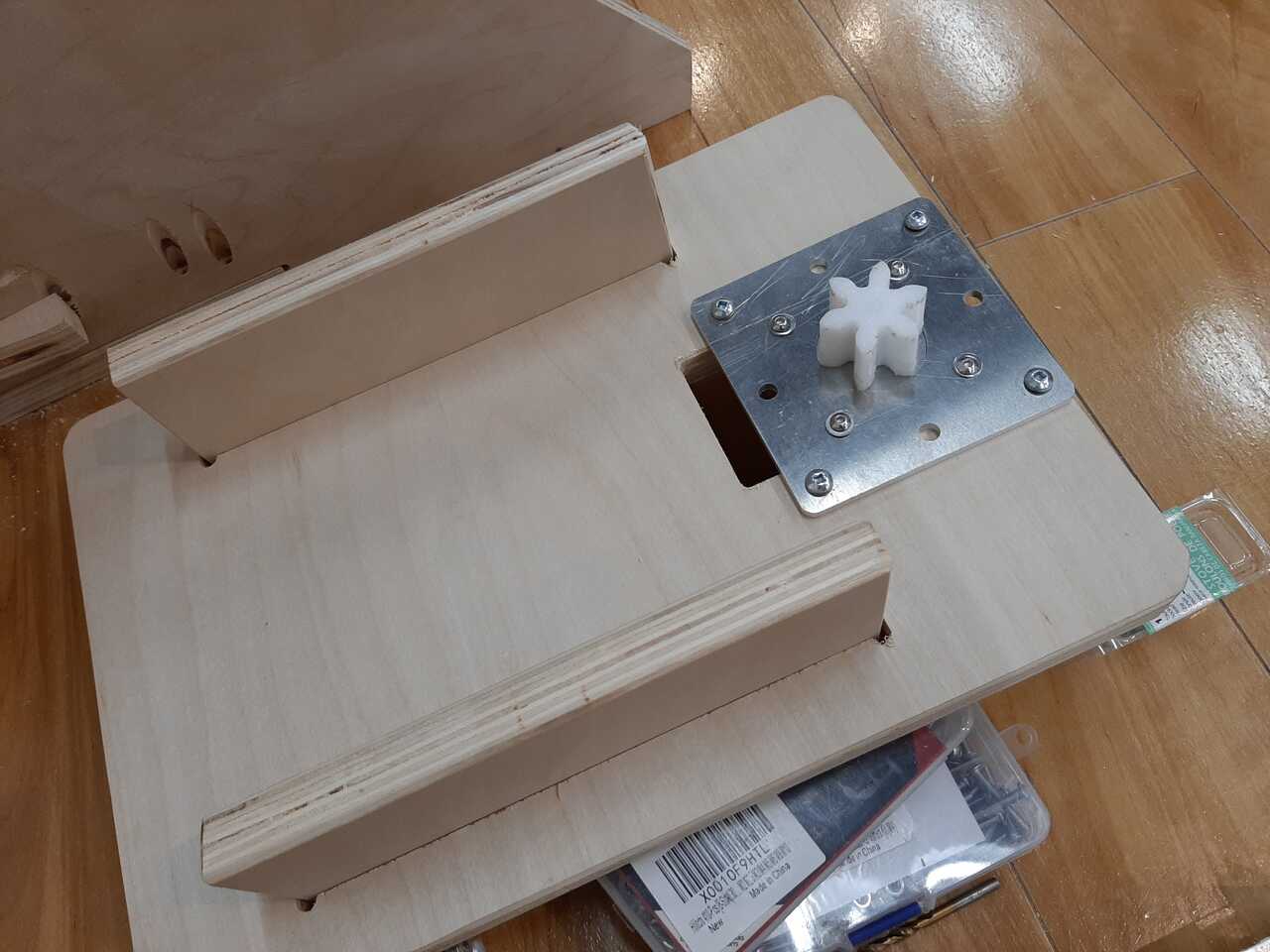
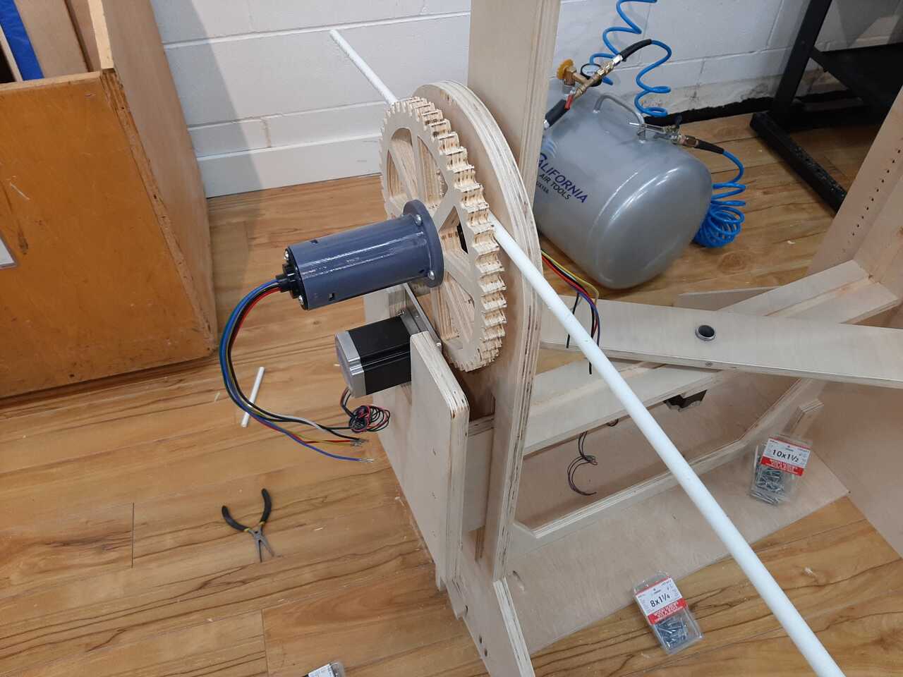
Assembly of motor mounts and gears
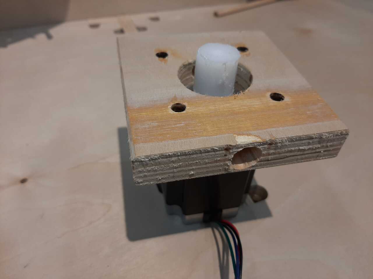
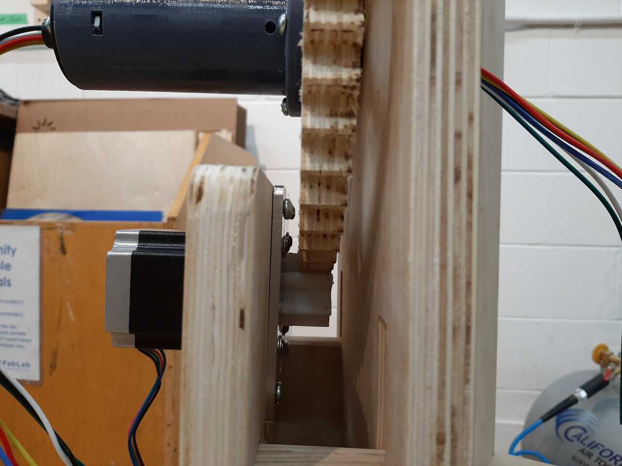
The next phase in the assembly was to assemble the motor mounts. The machine has two motors: one that is attached to the supports and uses gears to drive the outer frame to rotate on the x axis and a second motor that attaches to the outerframe to rotate the innerframe on the y axis. The photos below show the motor mount assembly. The x motor was mounted to the motorbox using a mounting plate and screwed to the side, while the y motor was mounted to the outer frame using a hollowed out piece of wood and the shaft plug.
x motor mounted to support and motor box
y motor mounted to outside frame
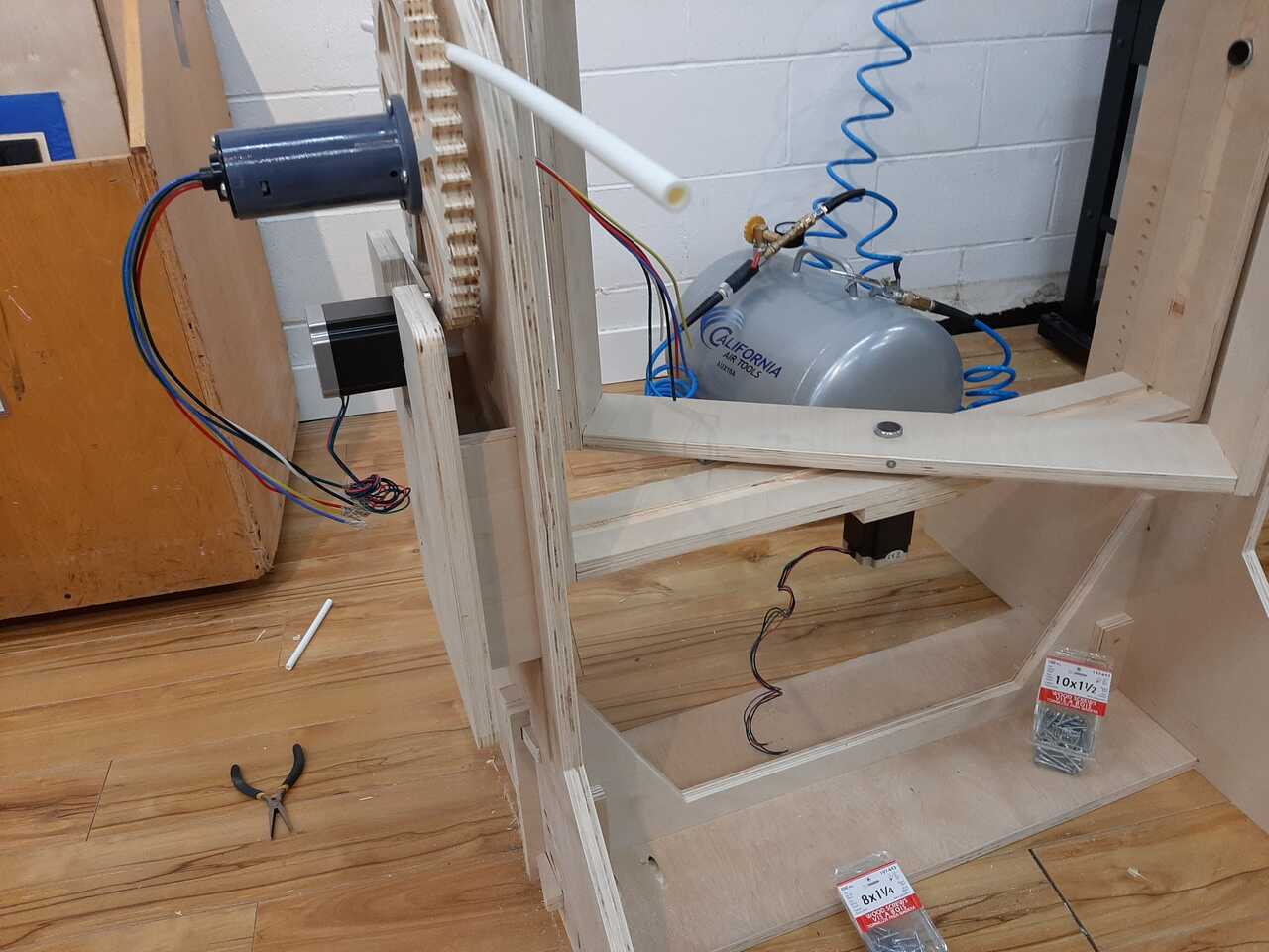
and lastly the gears were meshed and the motorbox was screwed into place to ensure that there was a snug fit between the gears. Note that the design allows for adjusting gear ratio by either changing the height of the motorplate or by changing the height of the motorbox.
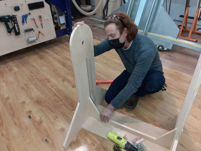
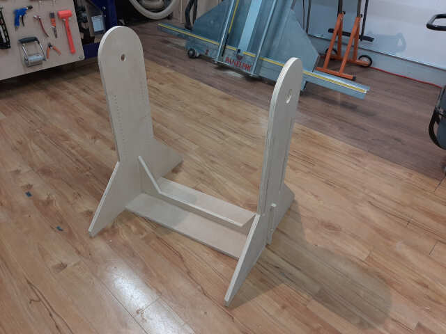
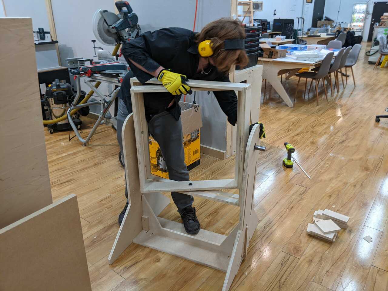
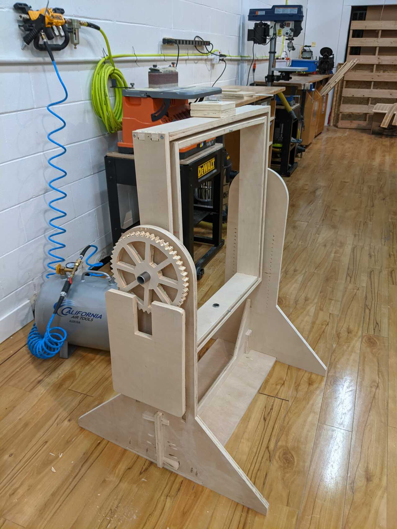
The last thing was to take a photo of the final assembly.
Final assembly
Below is a photo of the final mechanical asssembly (less the motors and gears).
The next step in the machine building process is to begin wiring the electrical.
8. Wire the electrical
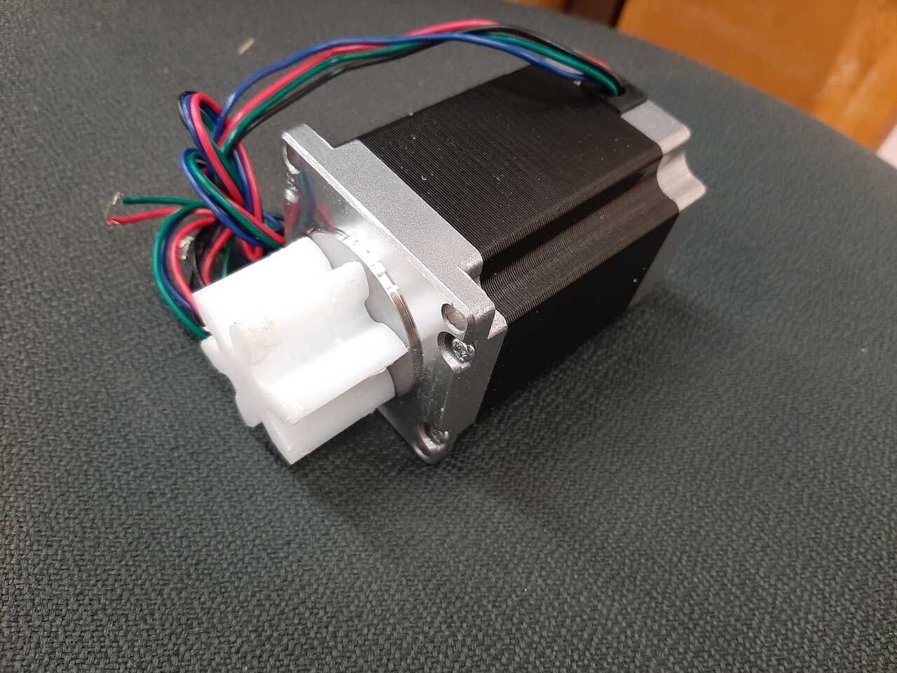
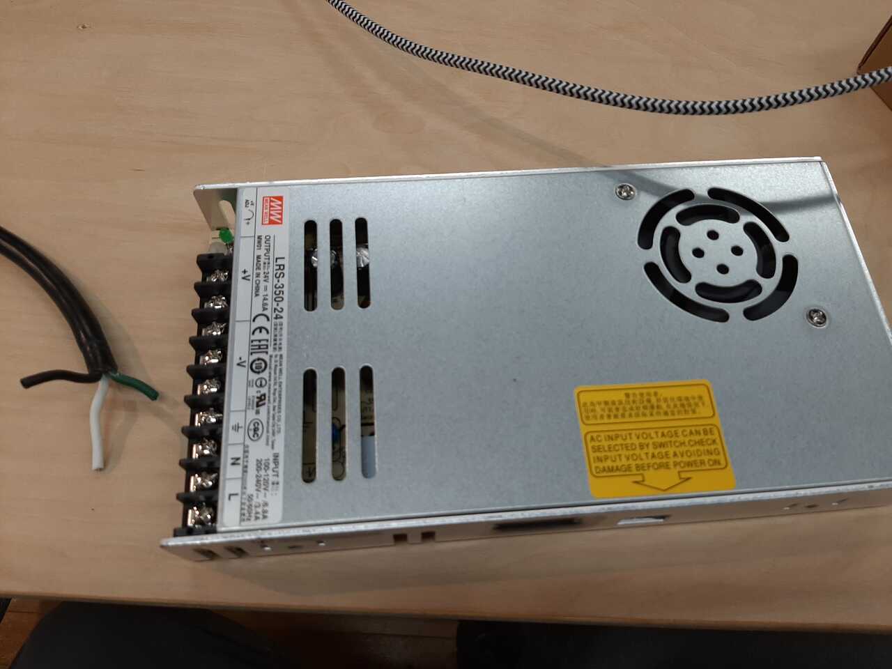
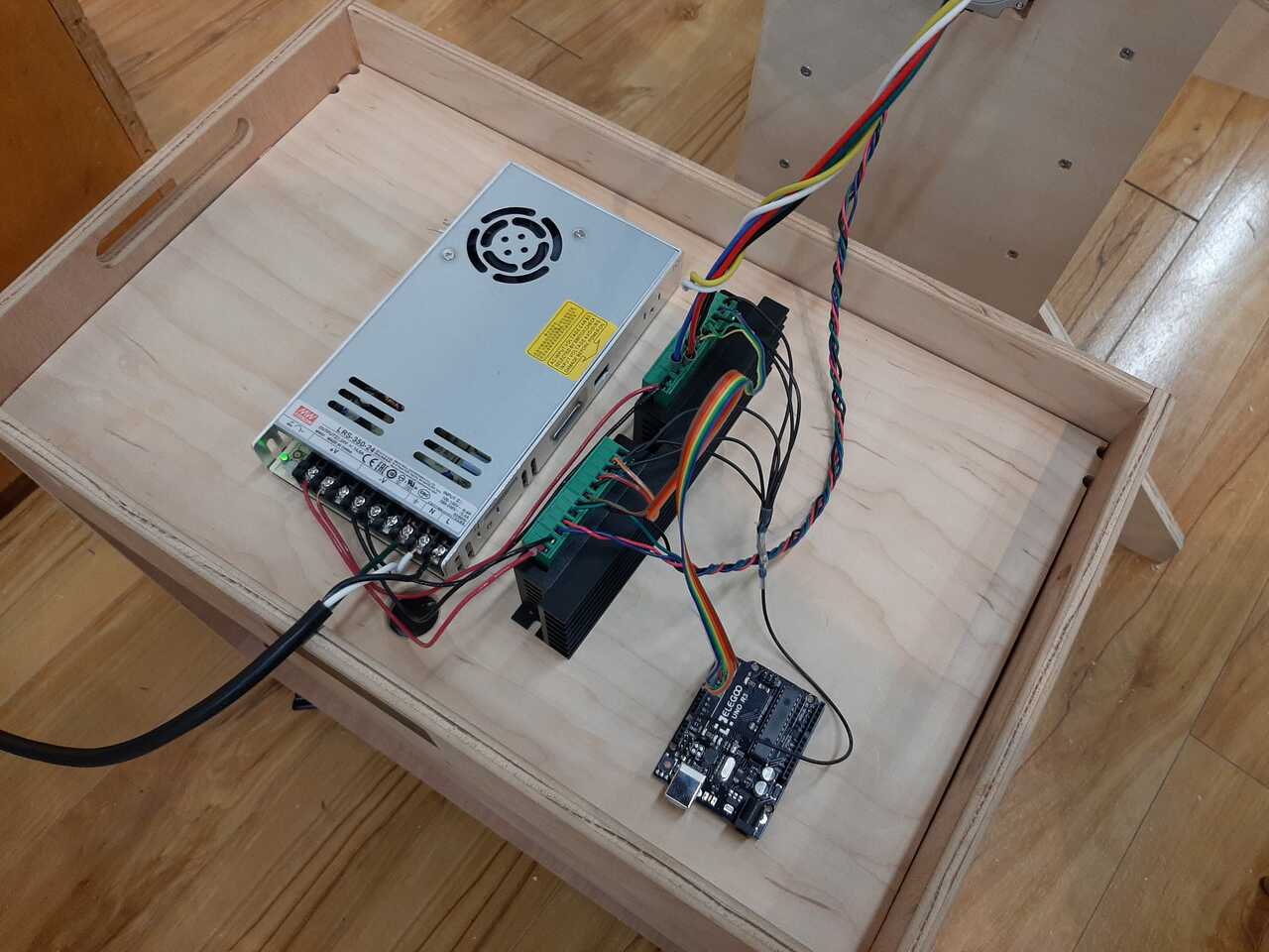
Now that the mechanical has been completed and tested it is now possible to move ahead with wiring the electrical. With this system we had two NEMA 20 motors that operate at 24 VDC. To run these we will need:
- 1 x powersupply 120 VAC -> 24 VDC
- 2 x drivers capable of operating at 24 VDC
- 2 x NEMA 20 motors
- 1 x Arduino UNO to flash grbl controller onto.
- 1 x Power cord to connect to power supply
A) connect power cable to power supply
To connect the electrical we need to connect the powersupply to the grnd neutral and live of the 120V side of the power supply.
B) connect positive and negative DC to the motor drivers
The next step is to connect the 24 VDC terminals on the power supply to the motor drivers positive and negative terminal (sometimes labelled VCC and GND).
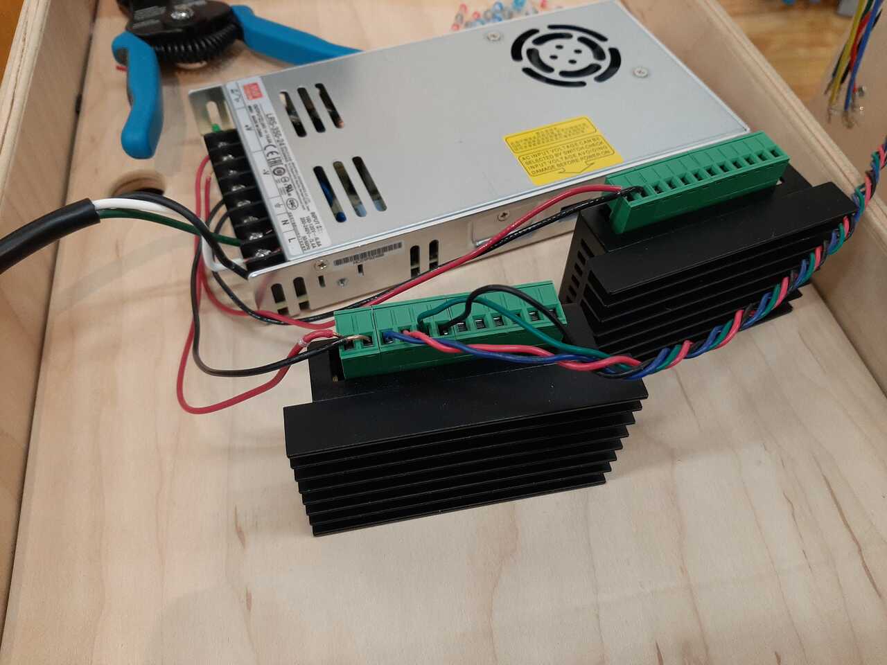
C) Determine which cables on steppers are the same pole
Next, using a voltmeter that is set to testing for continuity it is important to determine which is the A pole and B pole of the stepper motor. To do this you check which colors of cables result in a continuity trigger with the voltmeter when they are touched to it.
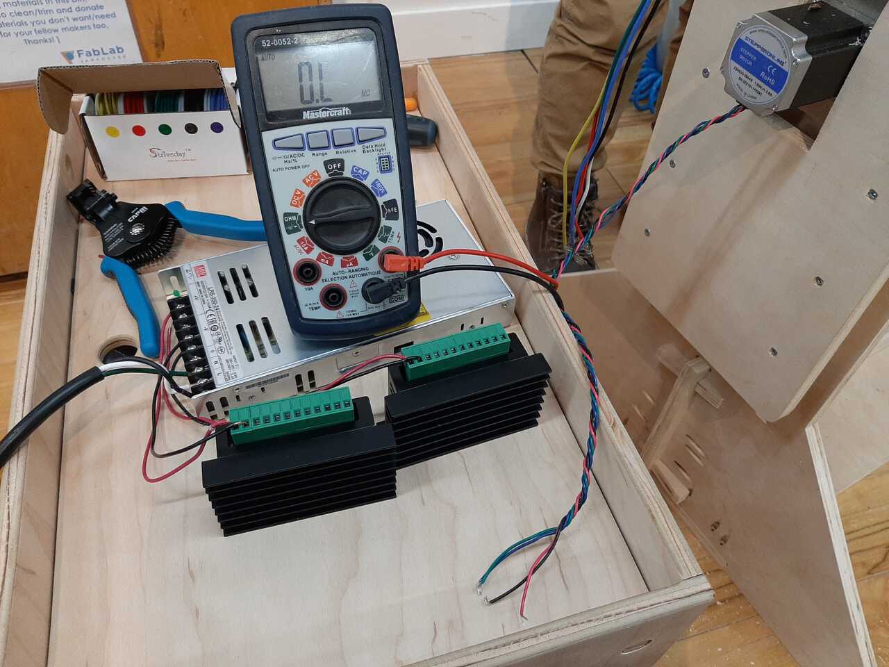
With these motors it was the red and blue making one pair and the black and green making another pair. Connect these to the A- A+ and B - B+ terminals on the driver.
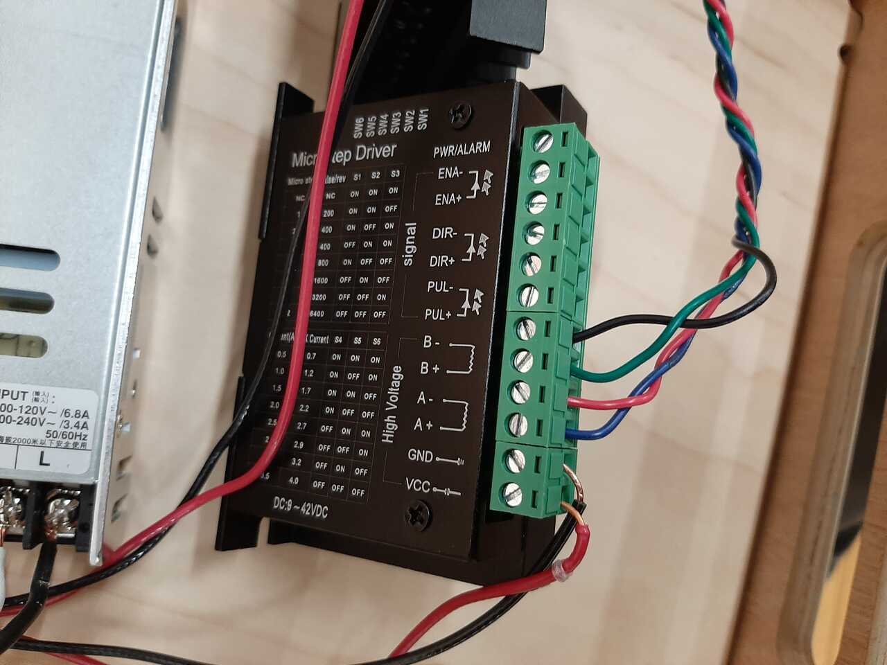
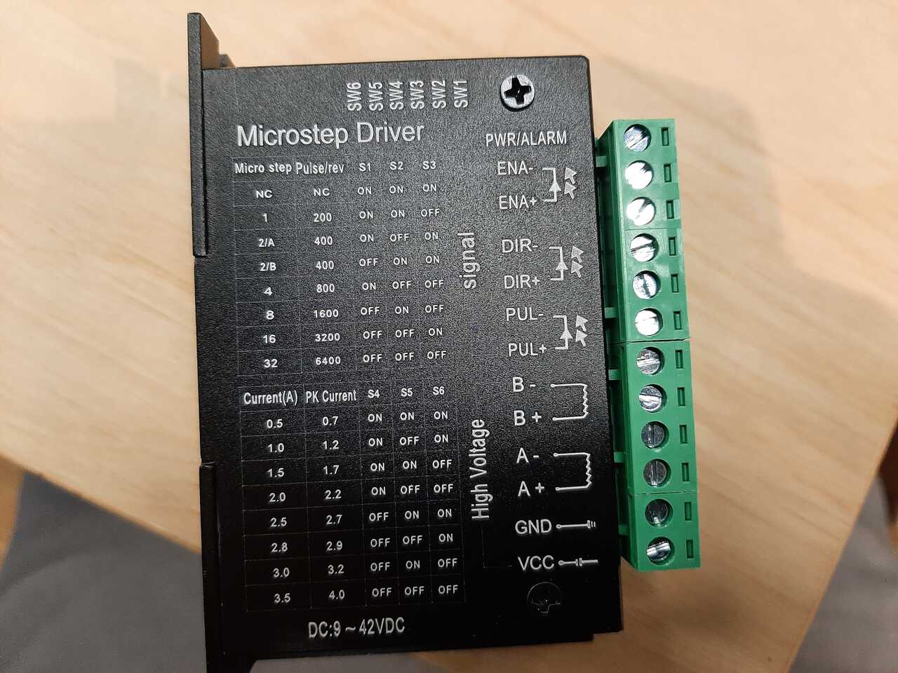
D) Connect the drivers to the arduino
Using the image below as a guide, connect the positive pulse (PUL+) direction (DIR+) and Enable (ENA+) to the respective pins in the Arduino. Connect all of the negatives together and connect them to the ground pin of the arduino.
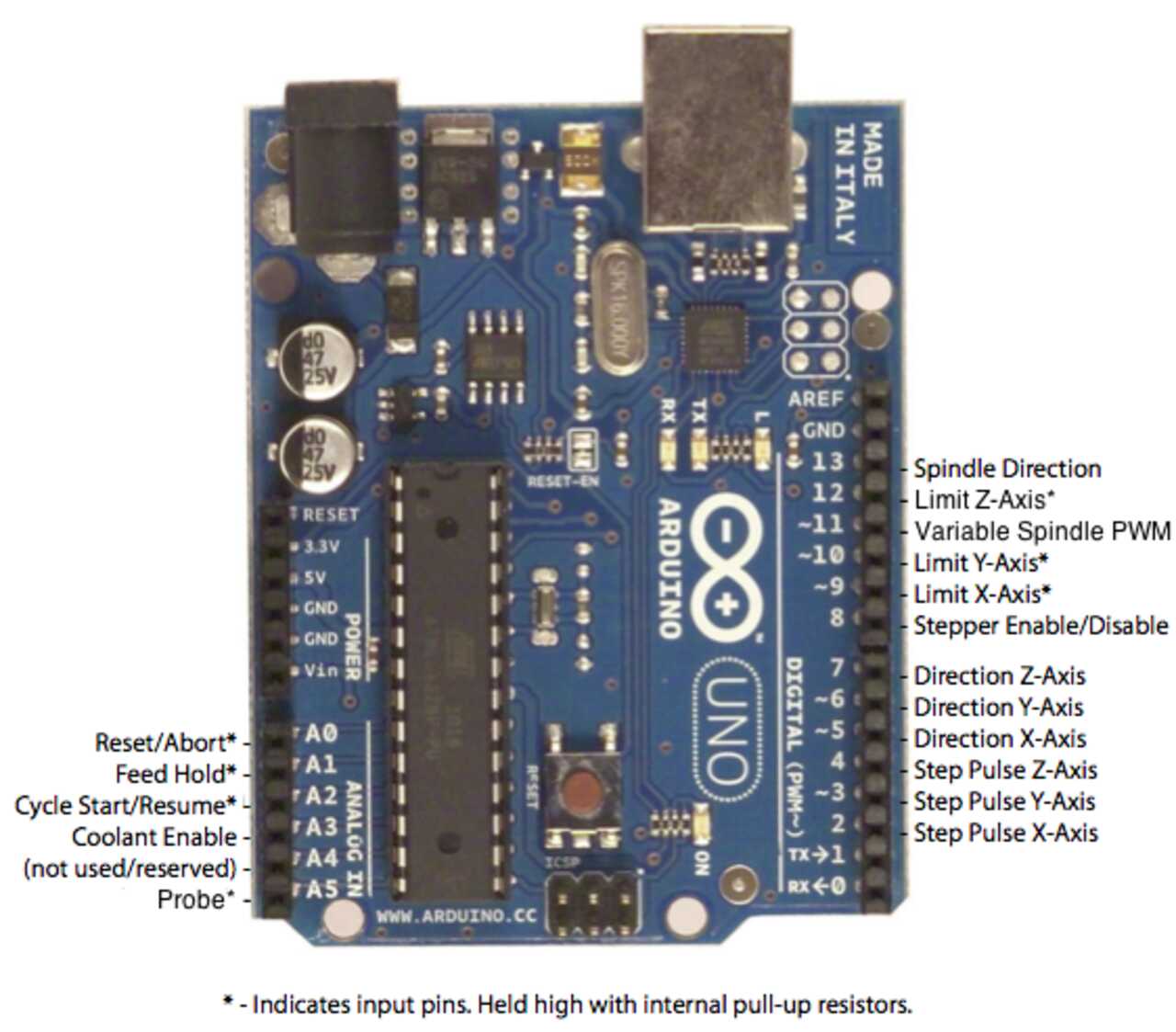
You can use the grbl GitHub page as reference if needed.
Once your Arduino is connected it is now time to program your circuit board.
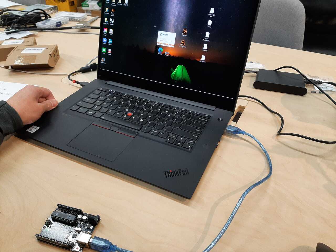
9. Program your circuit board
Programming the Arduino is very simple. All that is necessary is to simply flash the grbl program onto the Arduino by loading it as a sketch and uploading it.
The important part is programming your grbl controller which takes some of the following insight and calculations. The program we used was grbl. The instructions for downloading the controller, flashing it and much more are posted on the grbl wiki it is highly recommended that you take a look.
The interface we used to talk to the controller was the Universal Gcode sender. To program the controller we needed to know the pulse per mm (degree) to send so we used the following calculations.
A) Setting the pulse for motor x
the drivers have numerous options for Pulse/revolution based on the micro steps wanted. We were planning for an 8:1 gear ratio so we thought it would be best to chose a micro step of 8 and therefore a pulse per rev of 1600
since our motor would have to make 8 revolutions for one revolution of the frame we thus got:
1600 pul/rev x 8 = 12800 pul/rev
we then wanted to convert from one revolution to one degree so we therefore divide by 360 to yeild:
(12800 pul/rev) / 360 (deg/rev) = 35.556 pul/deg
therefore in order to obtain one revolution of the frame, the x motor (outer frame motor) had to be set at 35.556.
B) Setting pulse for motor Y
Motor Y is the motor that rotates on the inner frame. There was no gear ration with this motor. We wanted the inner frame to spin at double the rate of the outer frame. Which would essentially be four times less the speed of Motor X (8:1 gear ration divided by 2). Therefore using the same maths as above we yield:
1600 pul/rev x 2 = 3200 pul/rev
(3200 pul/rev) / (360 deg/rev) = 8.889 pul/deg
with that we can now test our machine
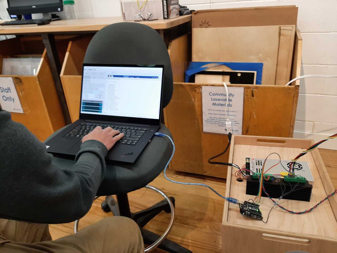
10. Test your machine
We ran numerous test by slowly increasing the speed and moving just one axis at a time. We eventually worked our way up to full speed to yield the following result.