Ninth And Tenth Week
Mechanical Design And Machine Design
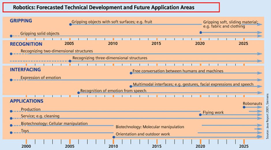
To this couple of assignment I had to design, produce and programme a kind of CNC or automatized machine. Following the trend, nowadays the developnment of technology is closer to our daily life as you can see at next picture.
I decided to create an functional CNC which can be used by content creators. I can be placed on your desk and you can dock your camera and link to your computer to control it and define the best position to you. Note: I only have a GoPro Cam with wide vision to test it.
Designing the machine
First I sketched my idea in Fusion 360.
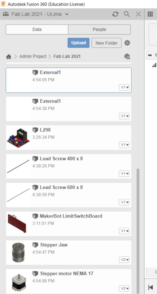
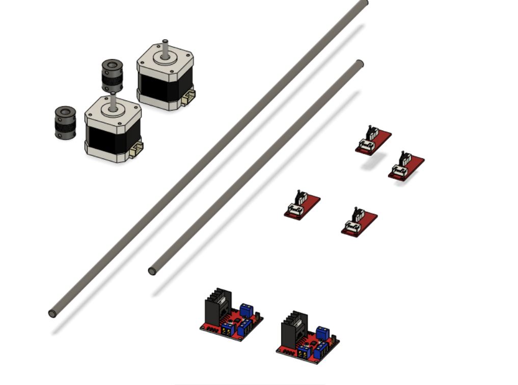
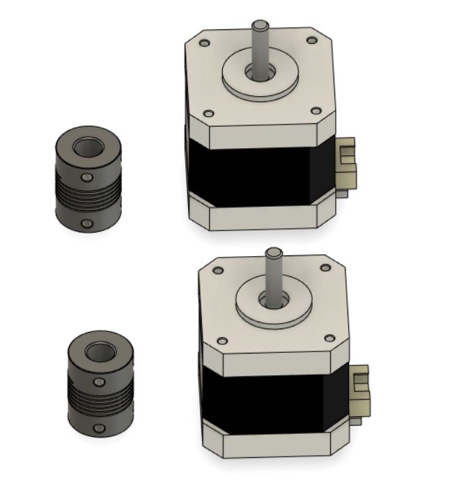
Then, I included some device to my 1st design fom GrabCad Library as ".step" files.
As you can see next I used these parts to complement.
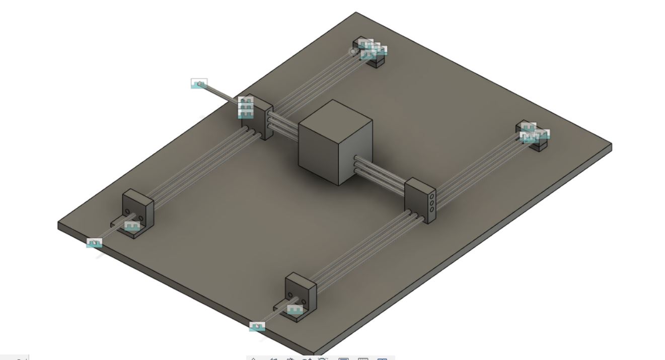
I started connecting parts to create the mechanism .
And creating some pieces and parts to complement the structure.
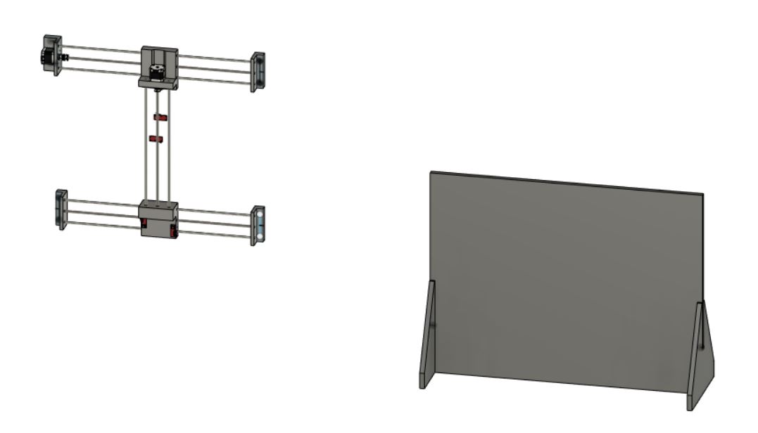
To finally started the assembly part of the process.
Final design
Ending with the design process I used a lot more pieces to make the mechanism functional.
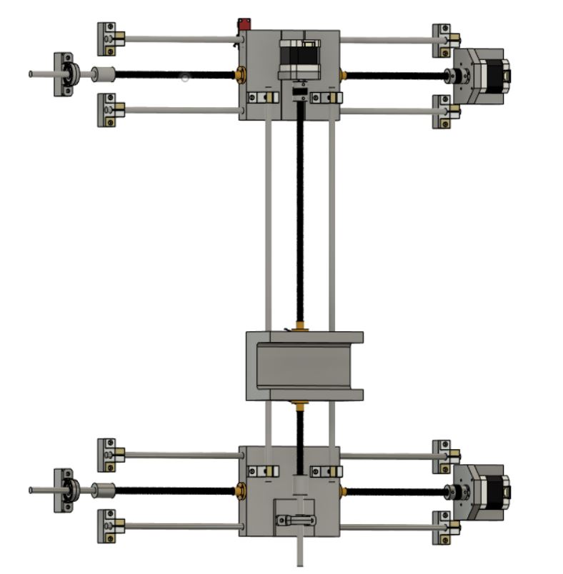
Next will be the different parts design.
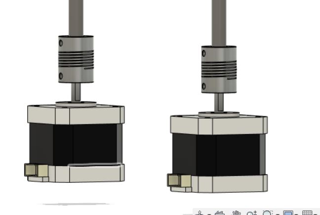
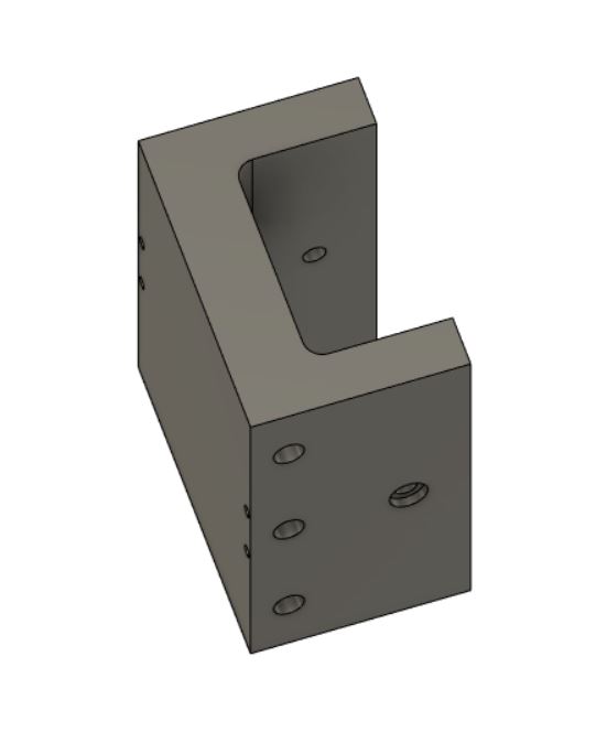
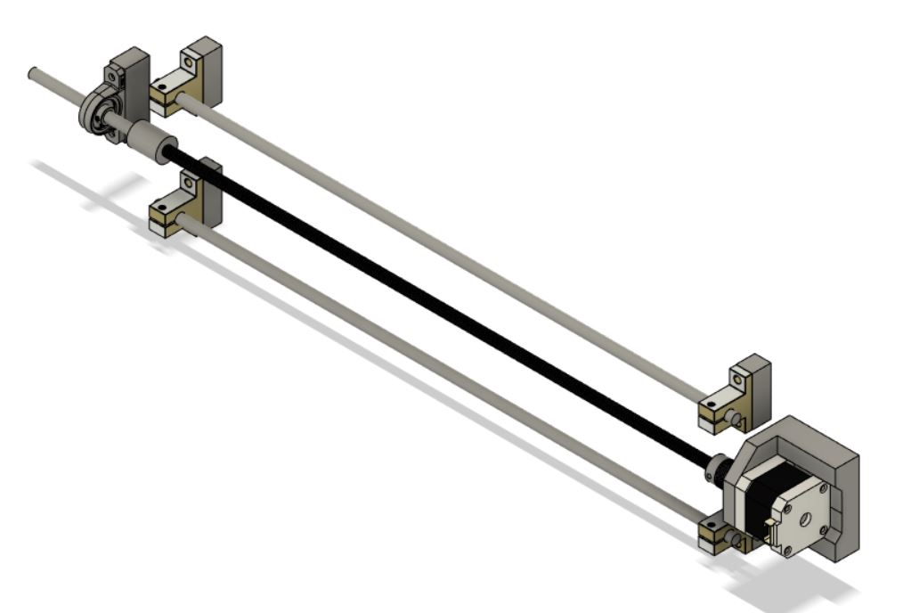
Here is the mechanism of the "X Axis"
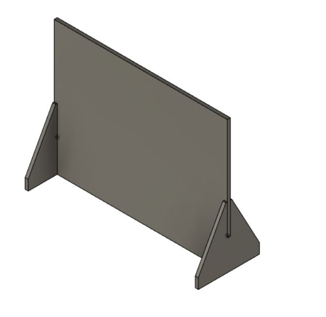
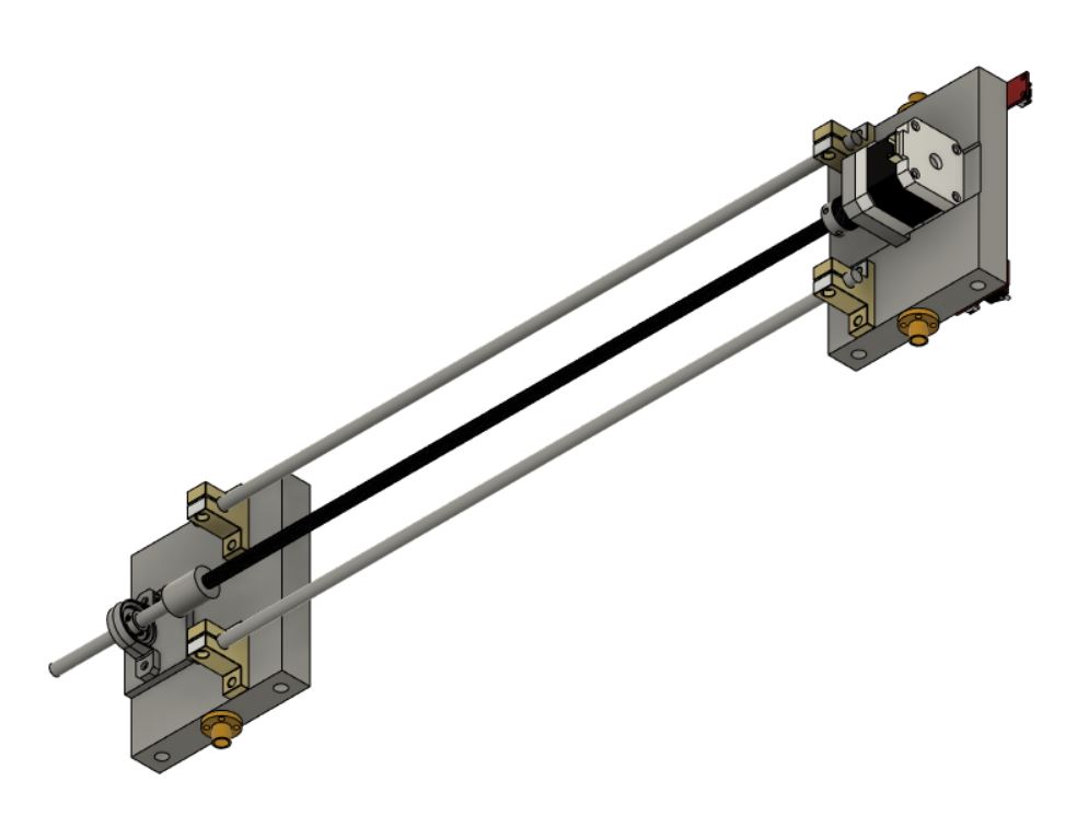
Now, the "Y Axis" mechanism
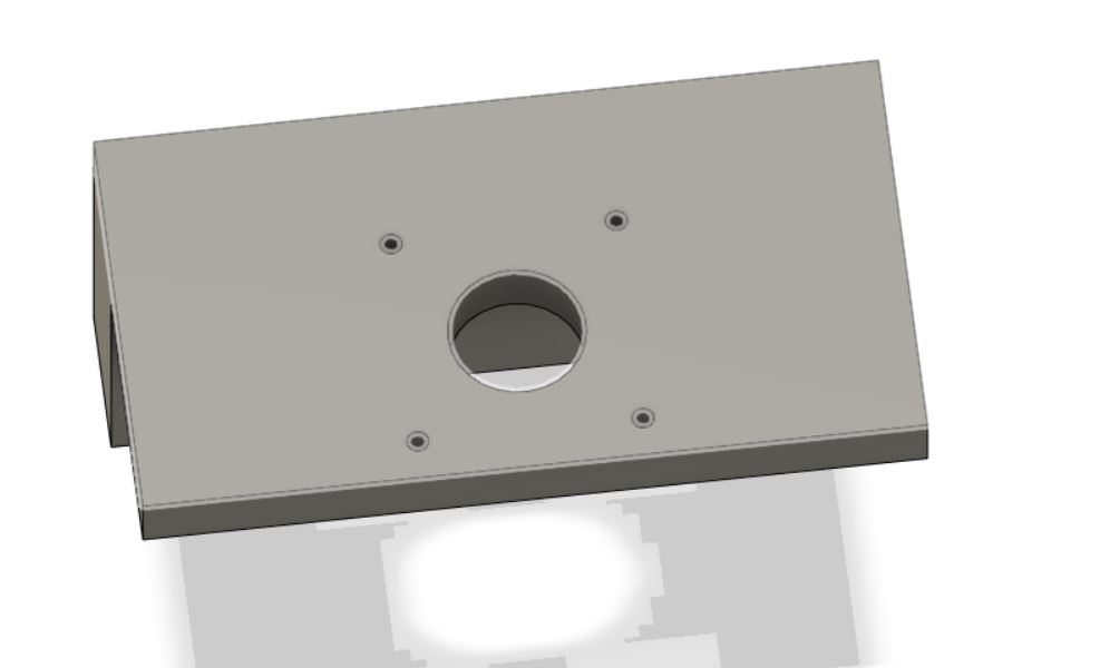
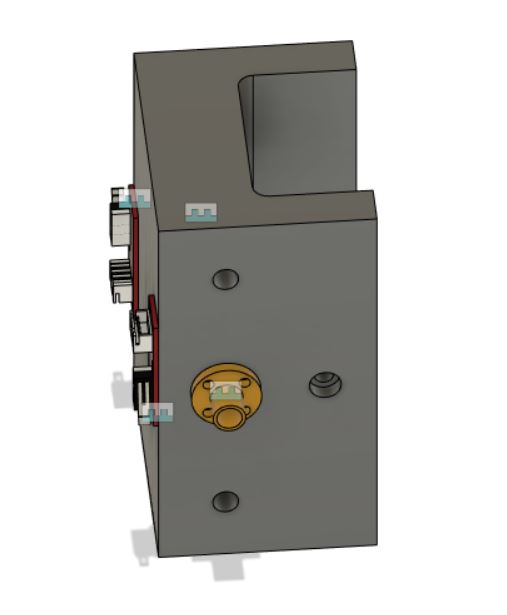
And the header of the camera
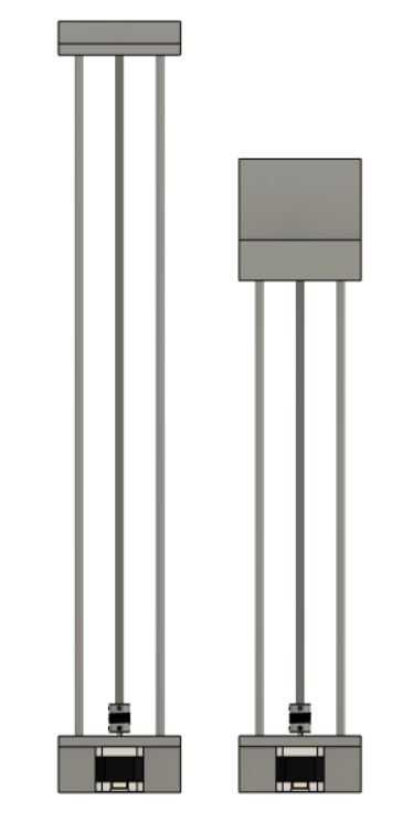
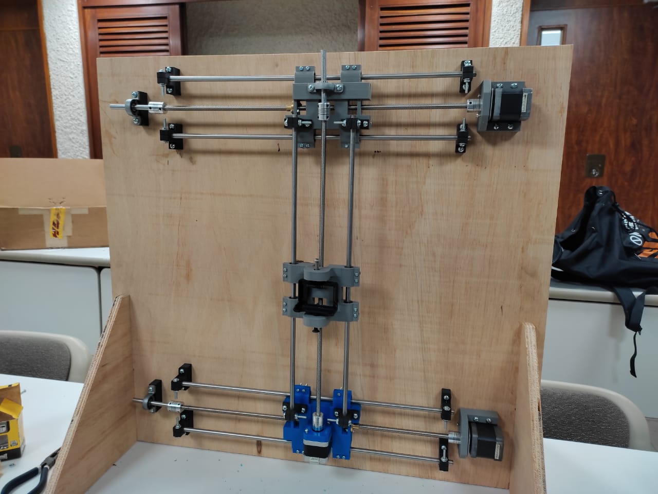
Finally assemblyng all I had this
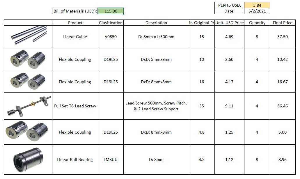
Note: Below you can find a simple table with the components I bought to create this CNC.
Time to produce
At this point I had bought all necesary material taking in consideration which I can produce and process at laboratory.
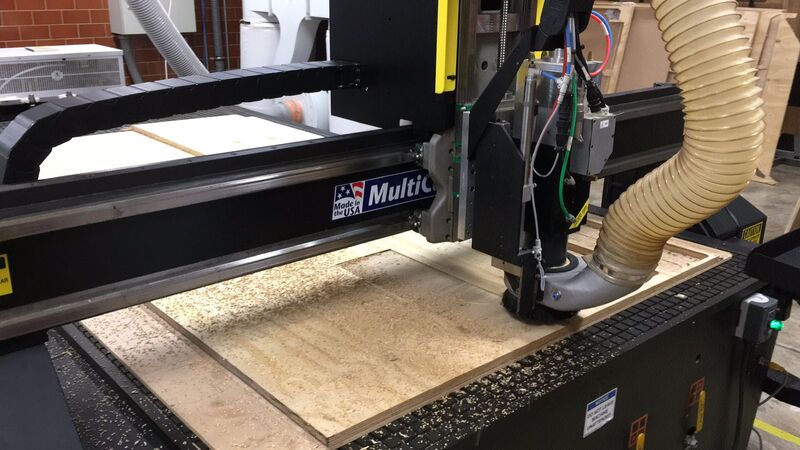
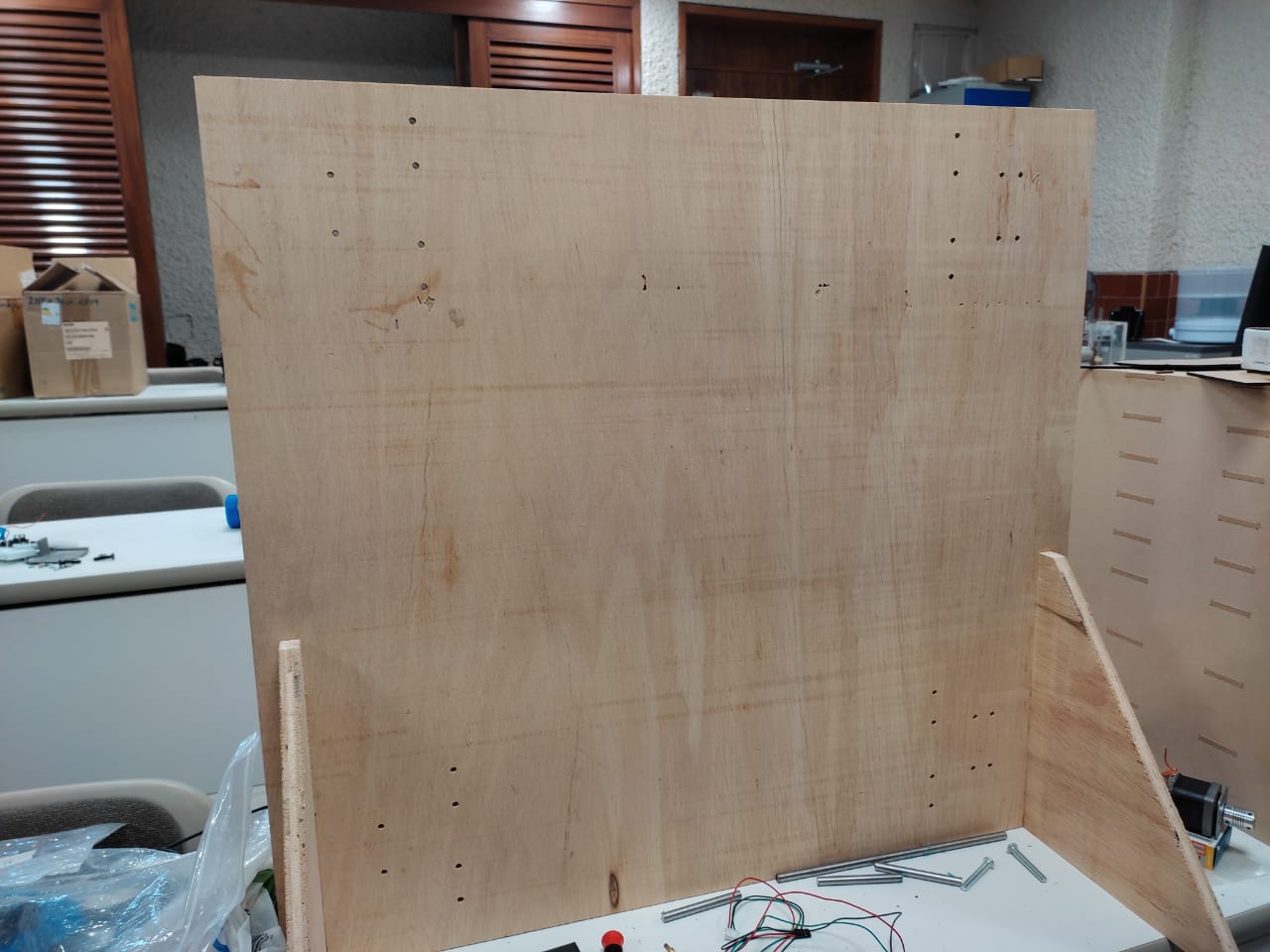
First I processed the back of my CNC with the MultiCam machine when I produced my Week 07 project using a 15mm triplay layer.
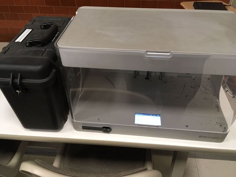
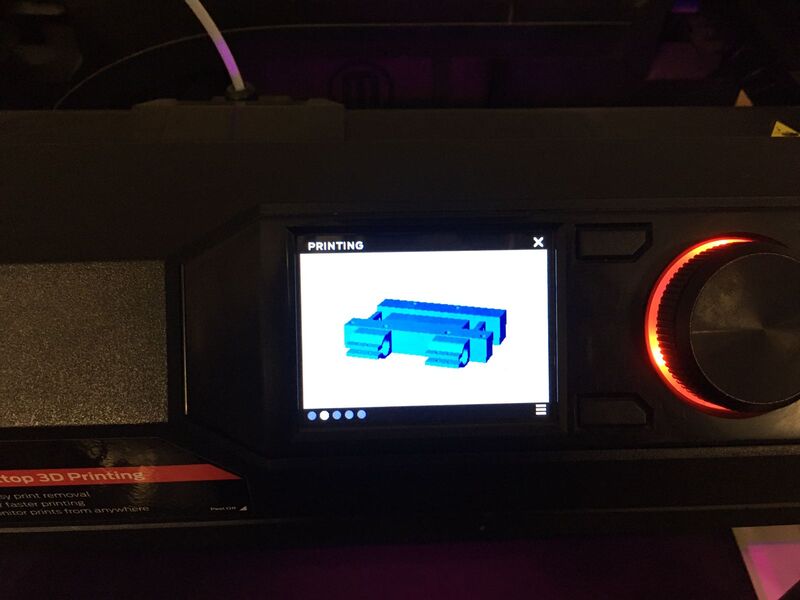
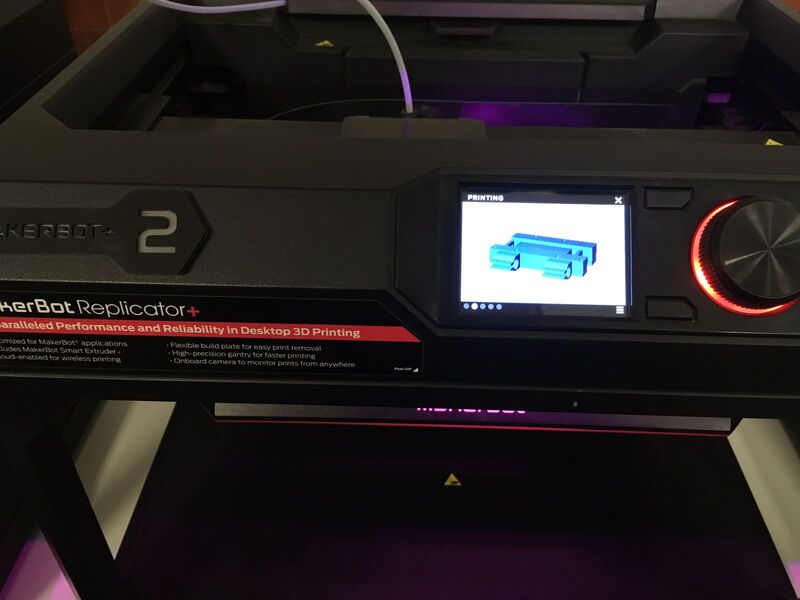
For the other part I used a replicator and, by that time, the most beautiful machine the Markforged
Which uses an online interface reducing the processing demand of the CPU using online servers.
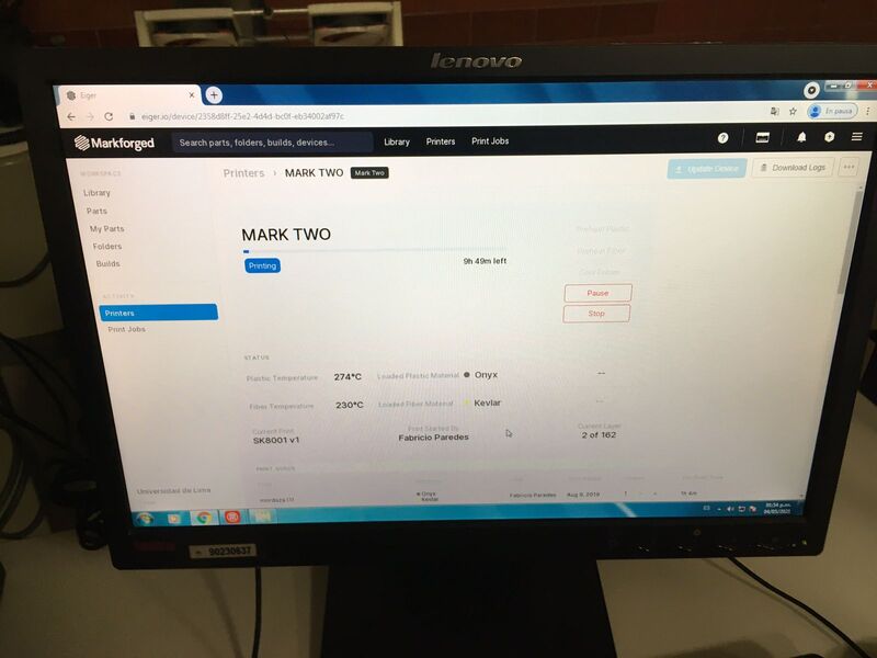
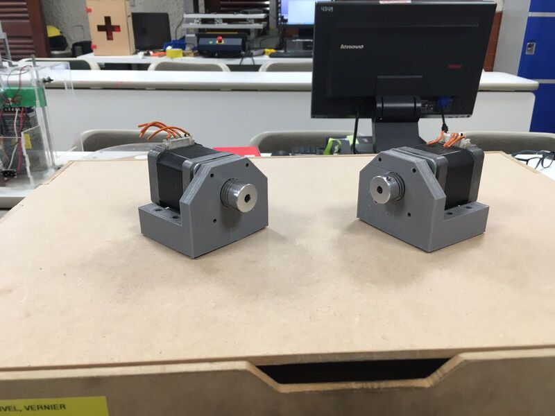
With this machine I produced my SK8 pieces and other pieces.
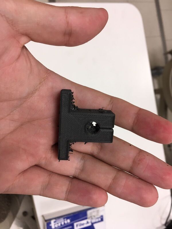
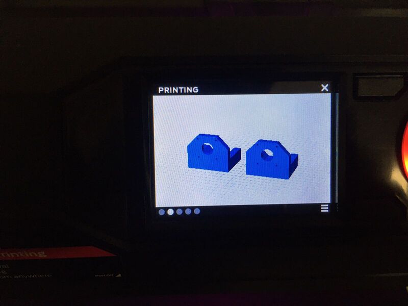
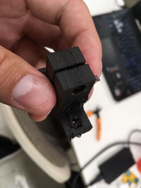
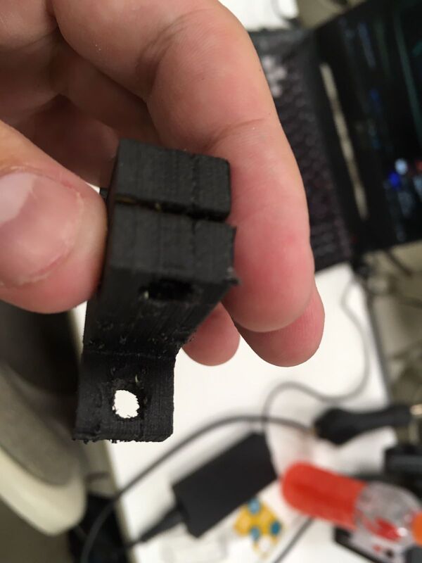
At the same time, I used 3 machines in parallel to produce 4 pieces. But before that I designed a kind of grip to test this functionality.
Source: I designed it.
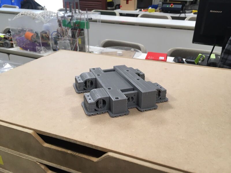
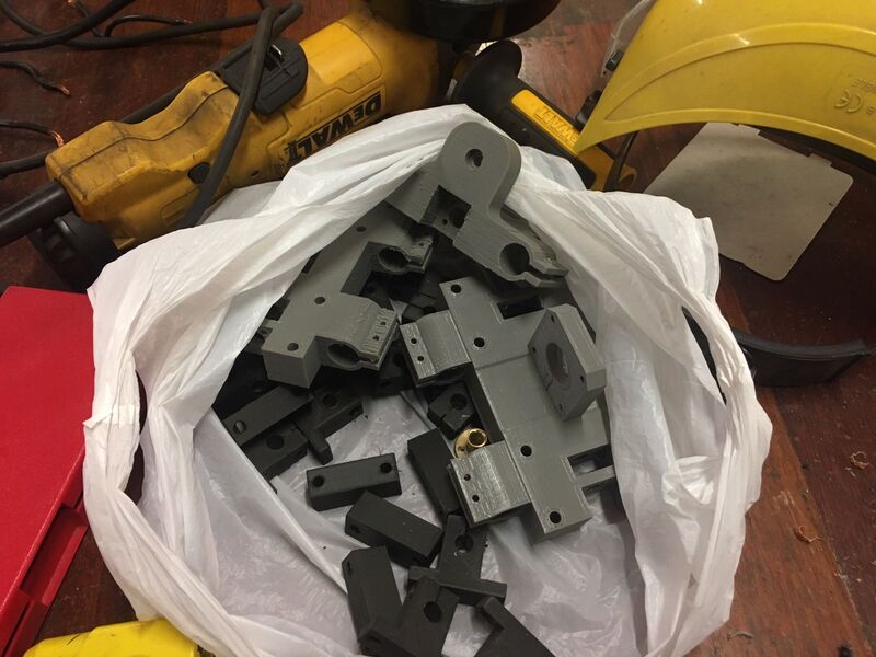
To finally have these.
Note: Unfortunally I did not realize about the picture quality of the other produced parts until was late.
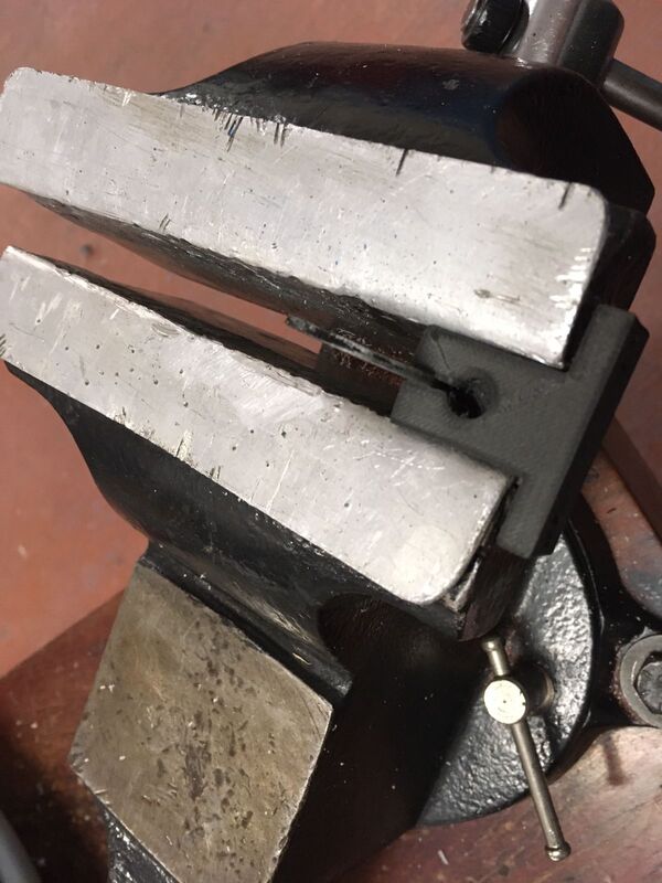
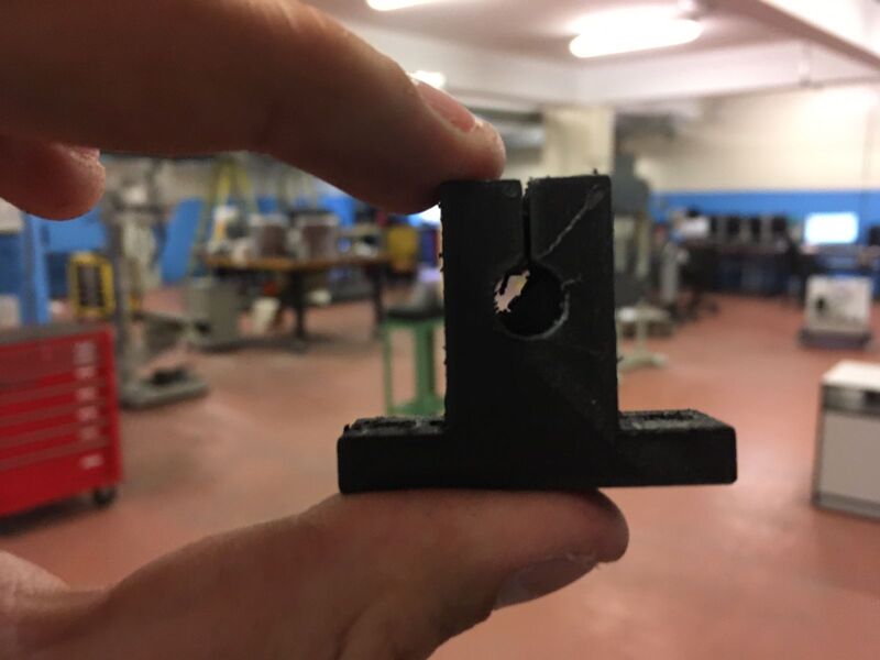
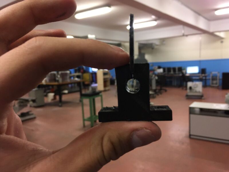
At this point I had to rectify each hole of each printed part:
so I used a bench vice:
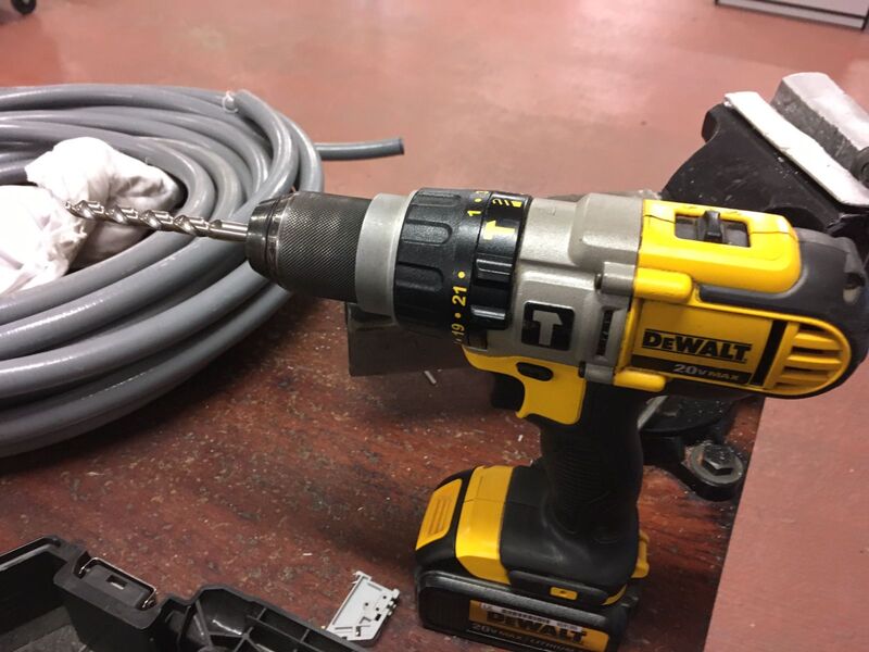
And a drill:
with some tools that the most common I used were 3mm, 4.5mm, 5mm, 6mm, 8mm, and 16mm to final have this.
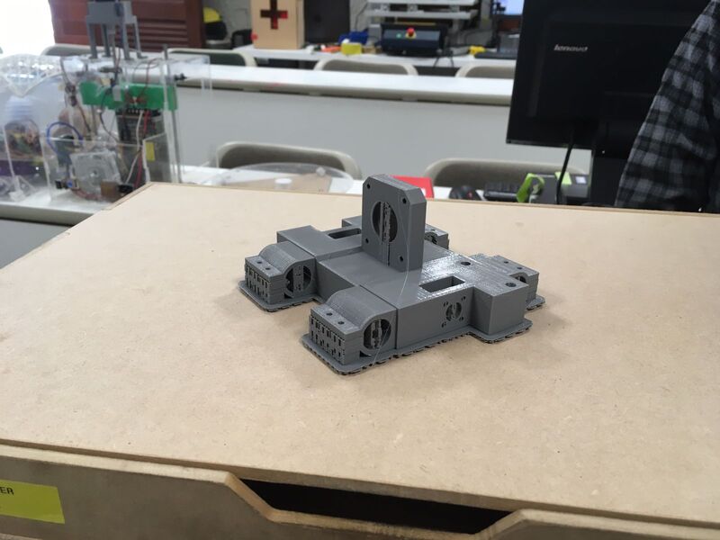
Here is the result.
Assembly time...!
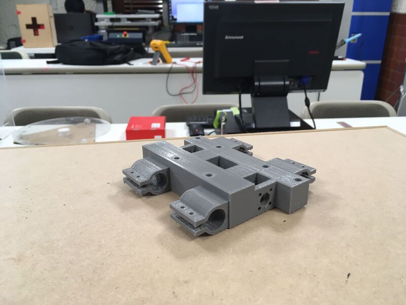
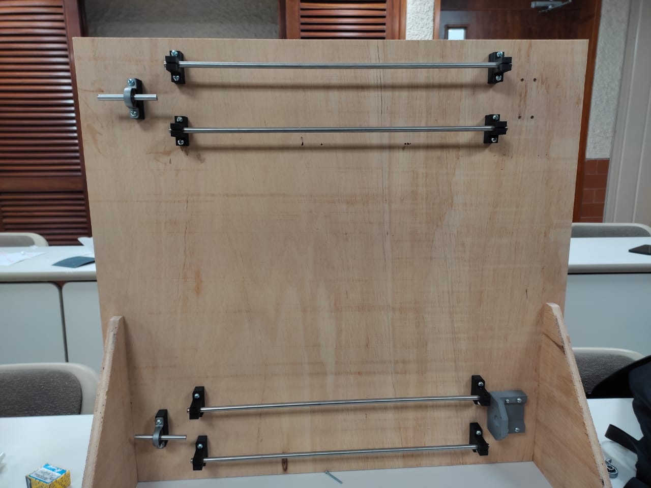
I started assembly the back of my project.
Then I put the 2 axis of the first part.
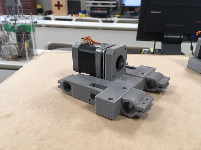
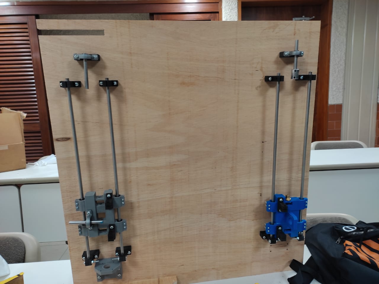
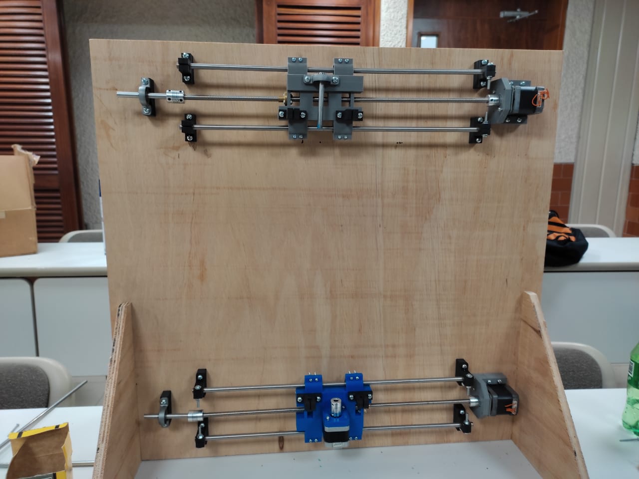
Next, I had to rotate the boady to put the nemas of those axis.
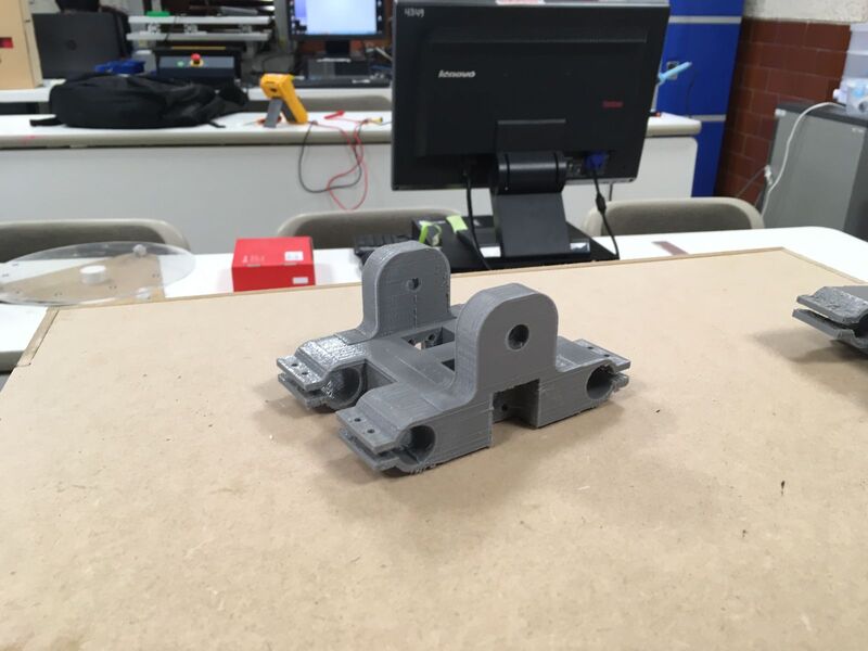
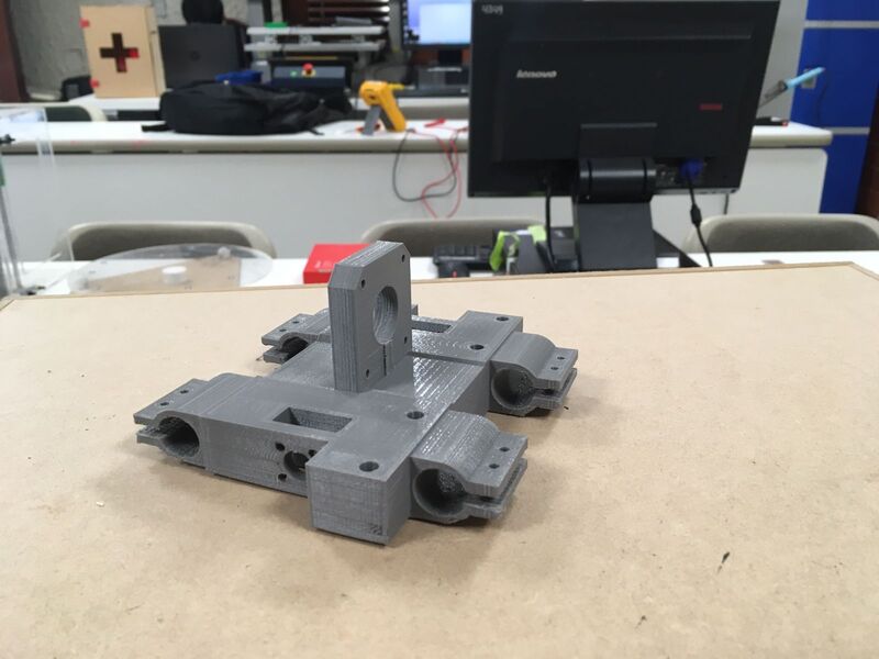
After that I assemblyied the 3rd Axis starting with the holders.
I finally had this.
Mechanical Test
Programing the machine
In this part I had to defined which drivers I will use and with what software I will control the machine.
First of all, this CNC is a 2D machine which will make possible to move and locate a VideoCam, Camera, or WebCam that in my case I own a GoPro so I design the Camera Holder based on that shape. I decided to use GRBL which is a great and practical envirnment to control your own CNC.
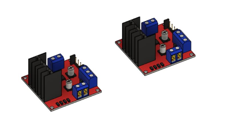
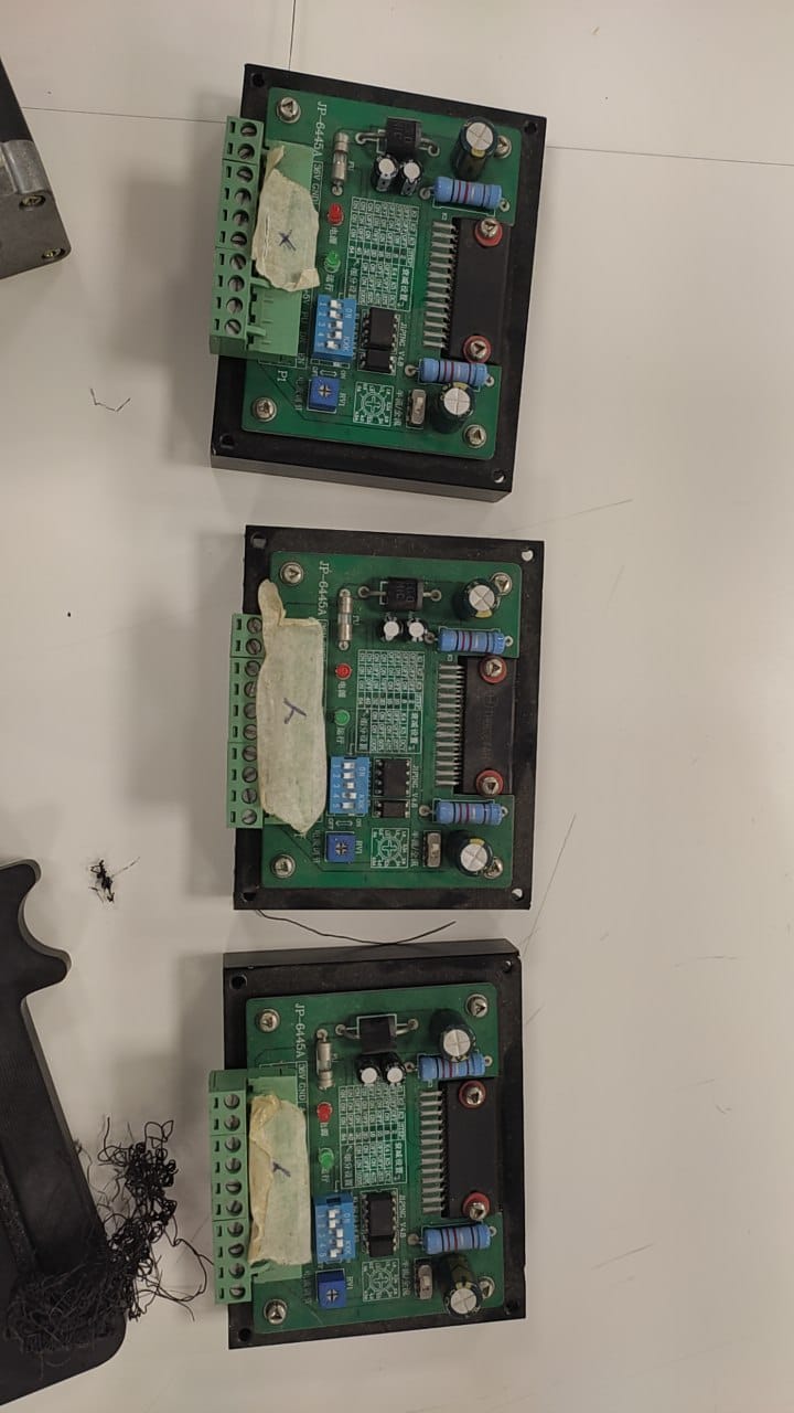
1st I used the THB6064 Drivers which our Lab has.
Then I had to wire my steppers motors so I had to recognize which wires I will use because each motor has 6 inputs. I tested in 2 ways: Using a Led and Using a Multimeter respectevely, let's check what I did.
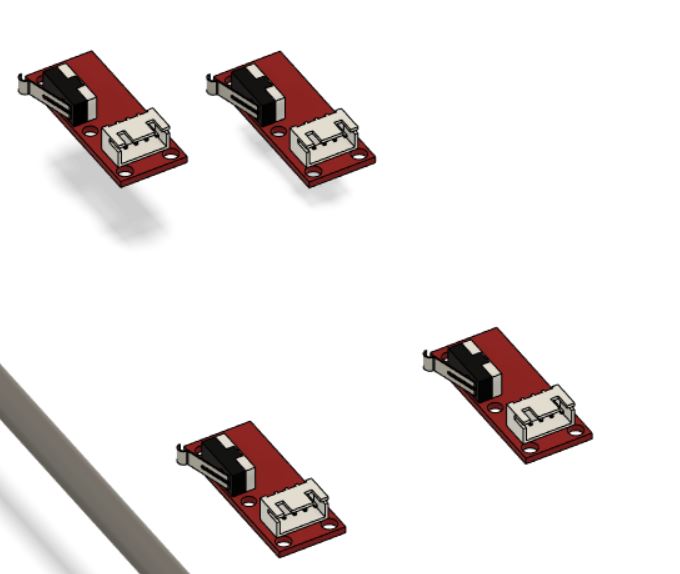
Using a Led
Note: Before start this test I soldered that female input block to plug easly the leds.
Using a Multimeter
Note: I highly recommend to use a Multimeter because is easier and you can identify which are the correct pins.
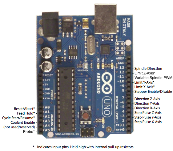
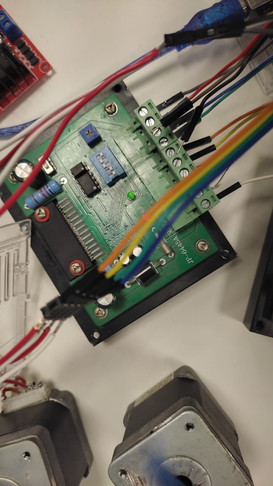
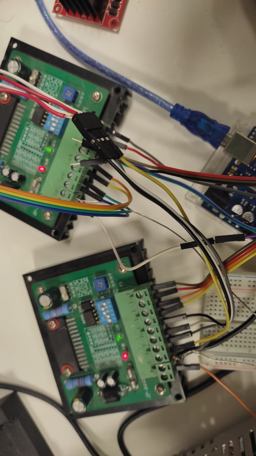
Having these configuration let me explain which I will use and which not. My drivers have 4 input each one which are plug to Arduino PCB.
2.1st. 5V: I connected these from 5V Arduino to each Driver.
2.2nd. PU: This means Step Pulse which refers the movement. I have 2 motors defined as X-Axis and 1 as Y-Axis so we can link both X-Axis' PU-Input to Arduino Pin2. And Y-Axis' PU-Input with Arduino Pin3. I left Pin4 unplugged because I don't need.
2.3rd. Dir: This is about the direction of Steppers Rotations and as PU setting I plugged together both X-Axis' Dir-Input to Arduino Pin5 and Y-Axis with Pin6.
2.4th. En: This is very important. These refer much more than enabling and disabling motors, this allows to Stepper motors changes the rotation disabling when is moment because when something is rotating in 1 direction a inmediately you change the rotation direction the motor will get break, in physics is called "Inertia". As 5v I plugged all 3 drivers enable to Arduino Pin8.
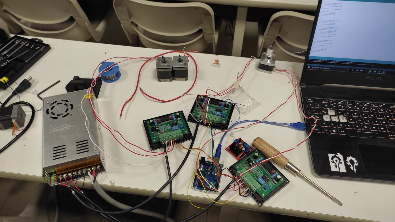
Note: As you can see at last picture I used a 24 Supplier to supply to my drivers.
Here is a video on the functionality.
3rd. Then was time to test in their final location and for this first test I retire the Y-Axis as caution action.
Note: All worked well so was time to locate the Y-Axis and do a test.
Note: I attached these test code down below.
4th. As final code and interface I decided to use GRBL and Universal G-Code Sender.
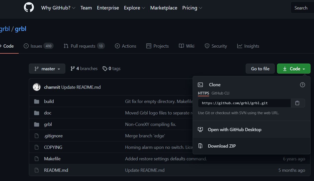
4.1st. To download GRBL we have to go to this page GRBL and download it clicking on "Code" button, then "Download ZIP".
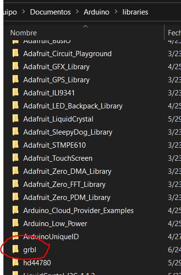
4.2nd. Then we have to Unzip and copy the "grbl" folder to Arduinos libray which mostly you can find in /Documents/Arduino/Libraries/
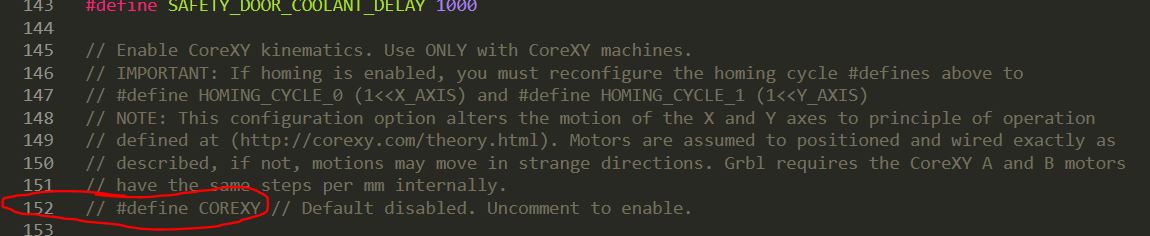
4.3rd. This part is very important. GRBL has a mode called "CoreXY" which is an other kind of CNC and do not consern to us. To check if this mode is disable we have to open an check "Config.h" file that I opened using Sublime Text 3 and check it was commented.
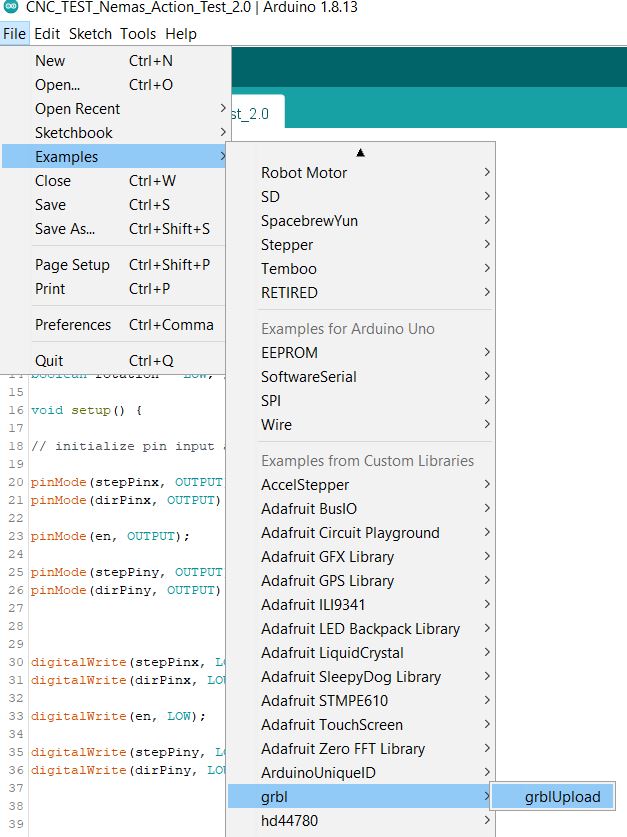
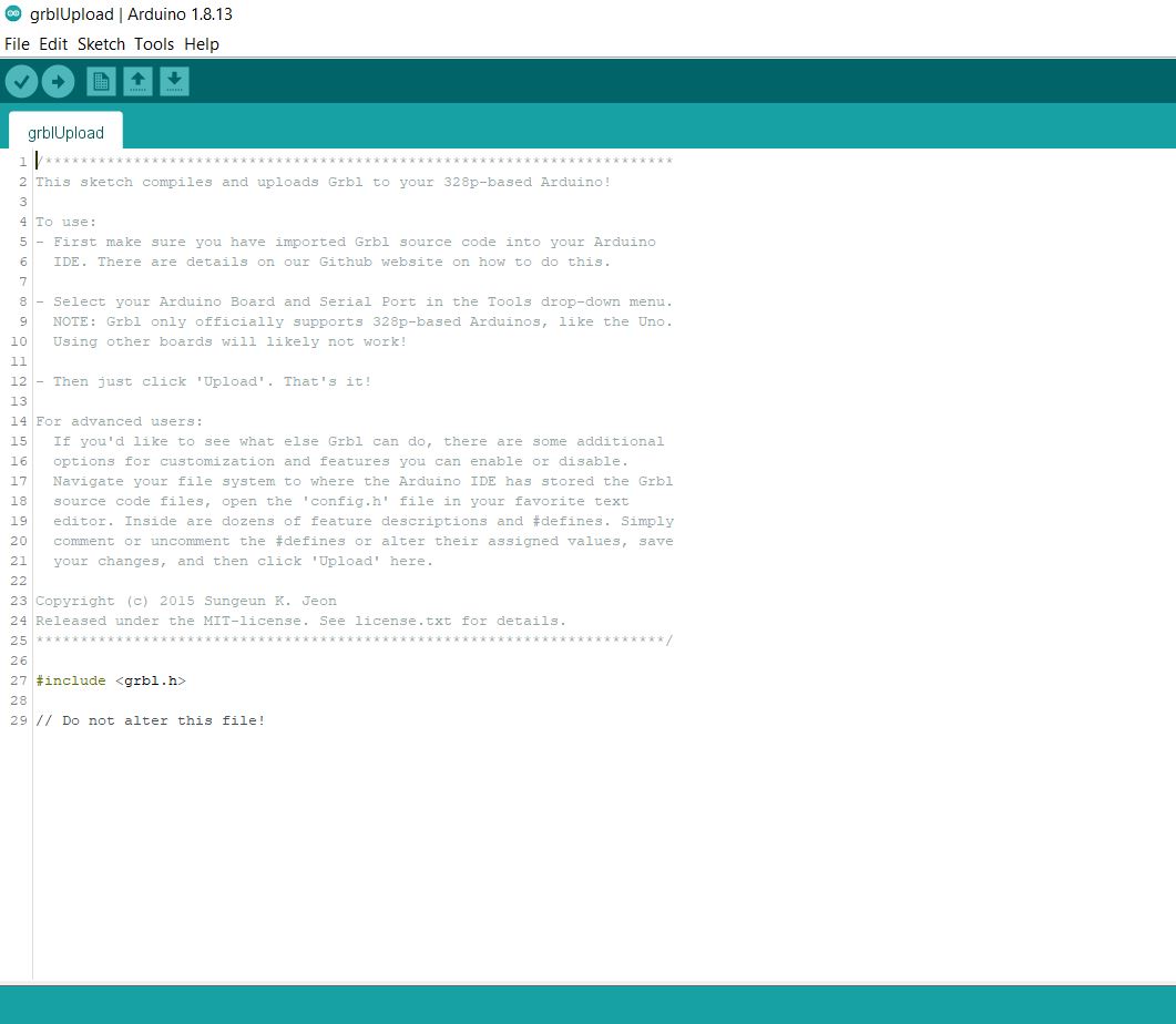
4.4th. Is time to upload to Arduino so first we have to open from Examples and then Upload.
5th. I used Universal G-Code Sender to set and use my machine. You can download this software going to the next page Universal G-Code Sender
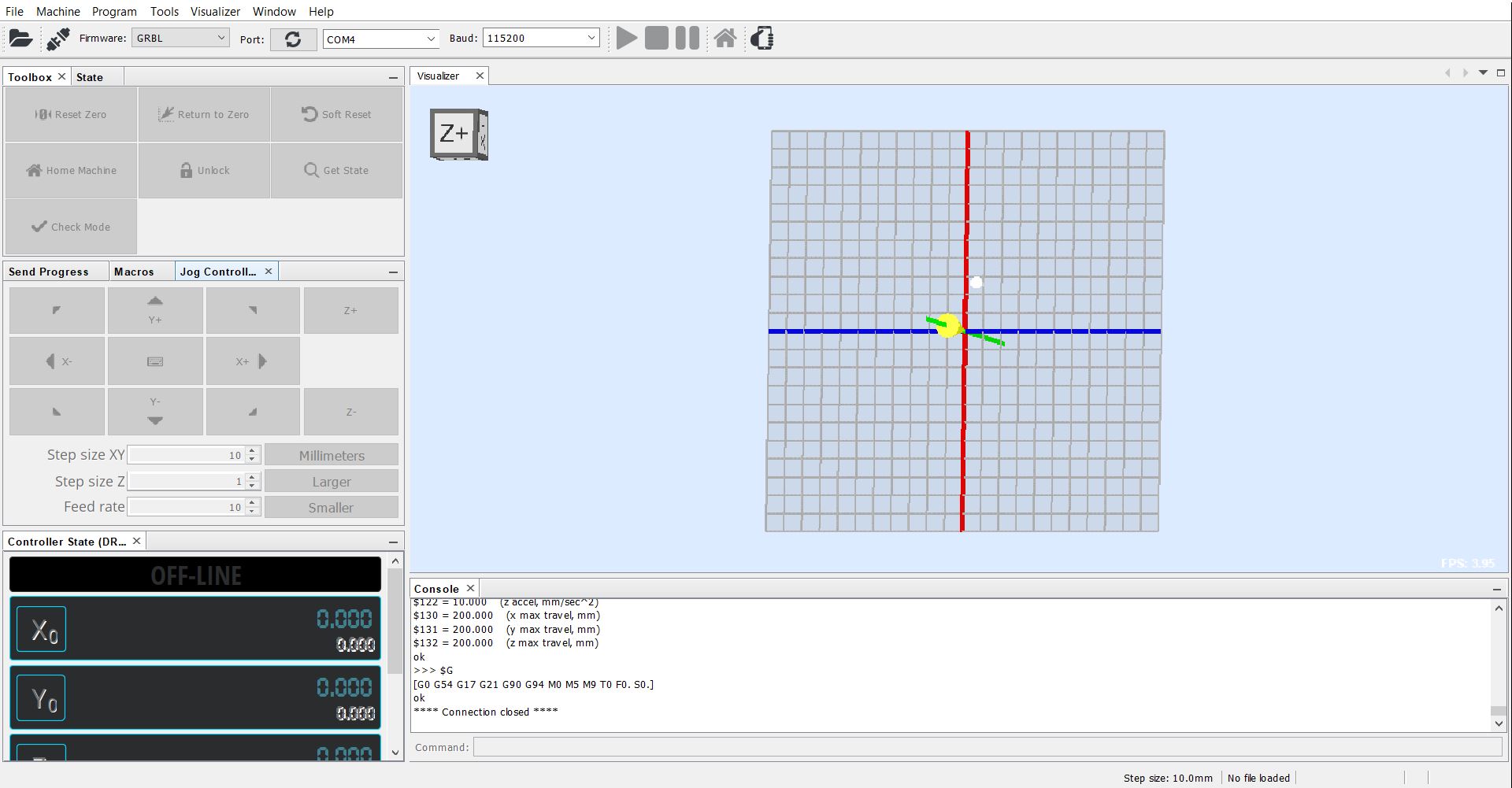
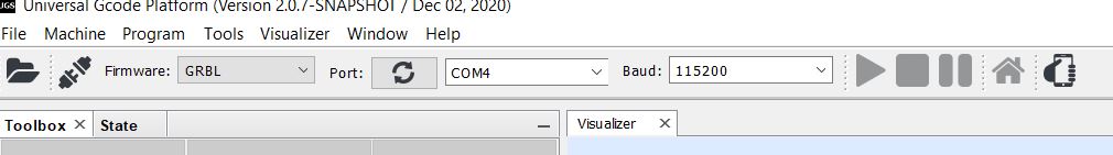
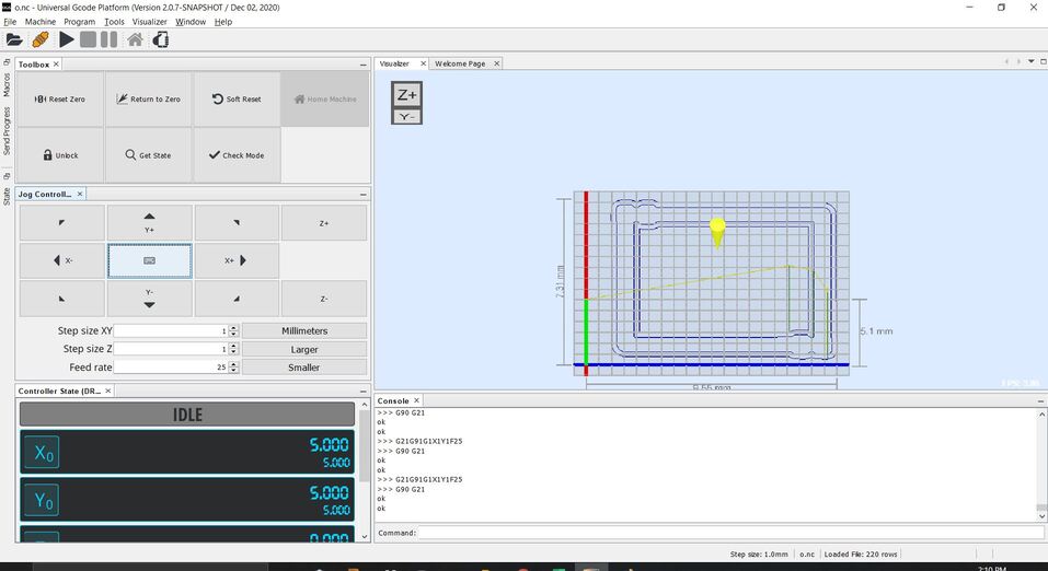
Having downloaded, unziped and opened we will see the next interface
As default we have these parameters: "Firmware:GRBL", "Port:COM4", and "Baud:115200", which are the correct settings for GRBL default settings.
And to link we have to click on the next icon
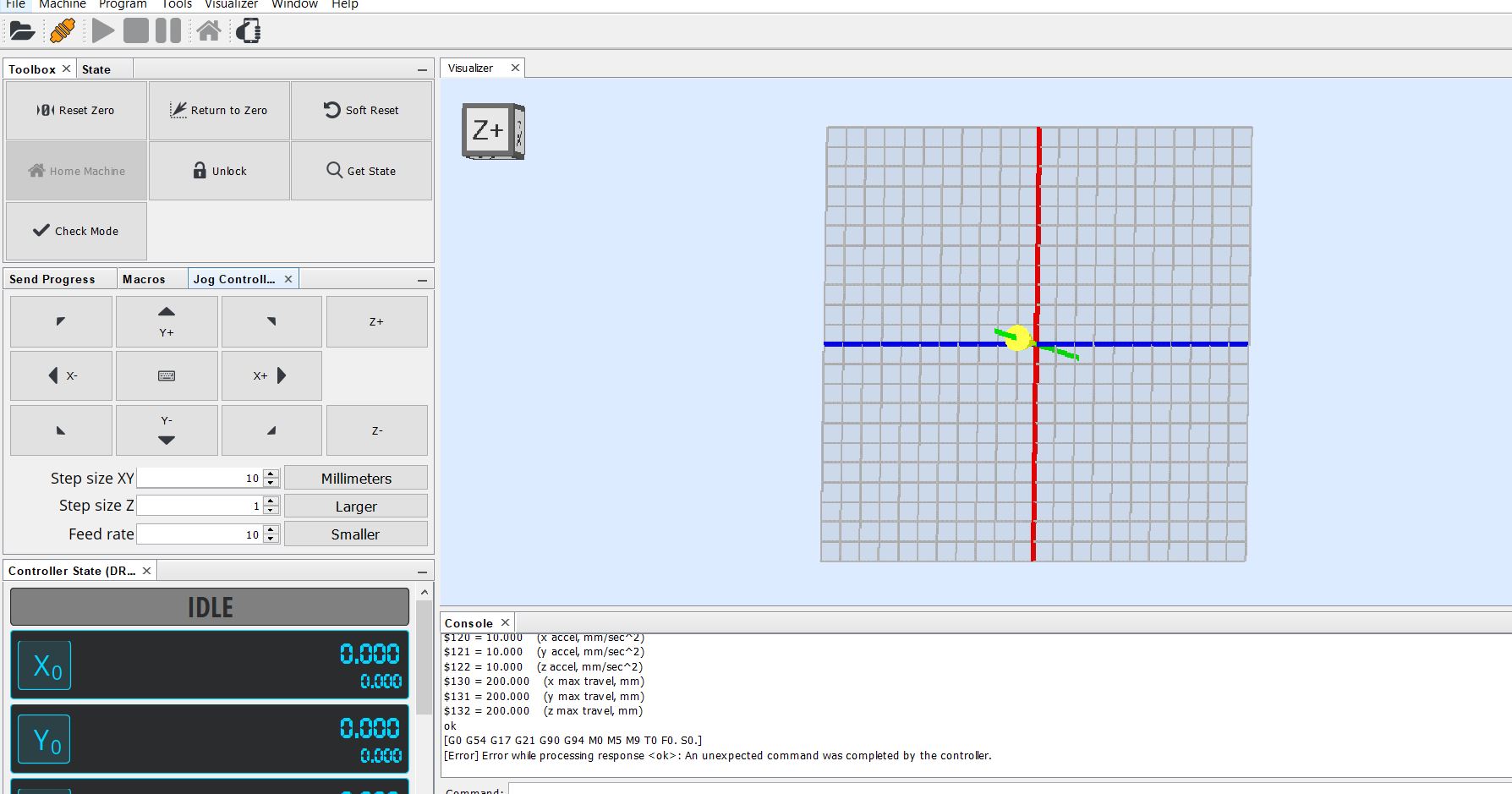
Finally is ready to use.
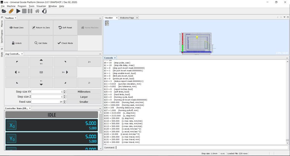
Then we have to set all our parameters typing some commands which can be find in this LINK and you will see these on a bottom-left window as next picture.
Note: Most of them start with "$" symbol.
And as additional I'm uploading a tutorial and my all my set parameters.
Note: I set 2133 steps/mm after made some tests. This was defined considering that for each 200 steps the stepper does a spin and after that my lead screw does for each spin 8 mm.
Then (200*8)steps/mm = 1600 steps/mm, isn't it?... Not, because when I tested that 8 mm was 6 in reality so I had to recalculate.
1600 steps is a 6 mm as X steps is a 8 mm. Finallly having 2133.33 steps/mm.
Ready to use!!!
Having finishing my machine which was designed, produced, cleaned, assemblyied and programmend by myself made me feel fulfilled.
Now, this is how to upload and automatized our machine
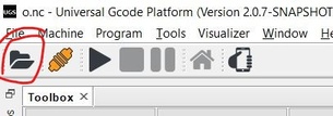
1st. At the interface we have to click on the next icon and find our file
After that you will see the process on the right screen.
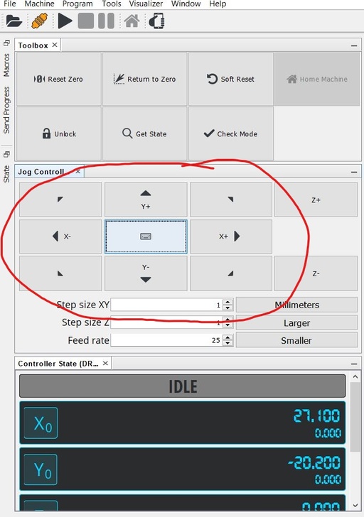
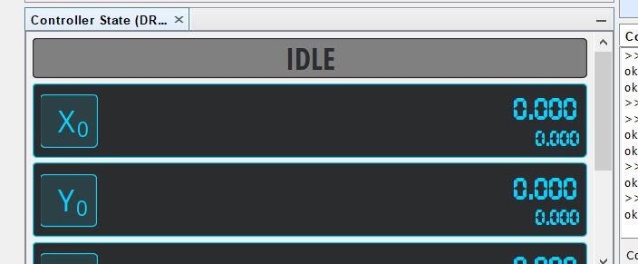
2nd. Now is time to set the start point so we have to use the panel control to move our CNC to the "Origin".
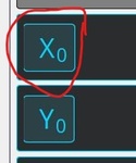
And when we had defined the origin press on the next buttons "Xo" and "Yo" to set X-Axis and Y-Axis respectively.
To have this.
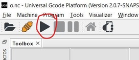
3rd. Finally is ready to start so let press.
CNCamera
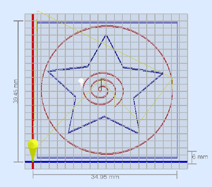
This is the path I designed to my CNCamera.
Note: I made the path on Inkscape. There are lots of tutorials which will teach you how to use Inkscape as a GCode builder.
And now I uploaded some videos of the functionality. Let's take a look.
Files
Below you will find my files which I made this week.