We started this week by discussing which type of machine we will make that will benefit our lab, the initial stage was searching at the beginning we have a lot of idea such as: food printing machine, conductive printing machine.
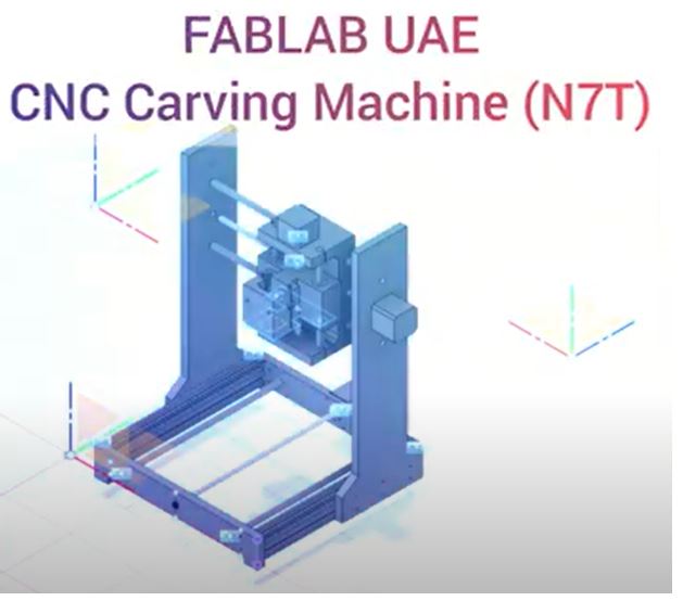
Then we decided to make a CNC Carving Machine group assignment page
The project will consist of three main parts we divided the roles according to these 3 parts:
1. Mechanical Design
2. Electronics Design
3. Software Design
Individual Contribution
I was responsible of:
1-Project initial Plan
2-Components List
3-X-axis mechanical parts: linear rail shaft support, and bed sheet
4-Machine branding
5-Machine Video production
Project initial Plan & Components List:
I design an initial plan to use while documenting the group contribution. Regarding the components list there were several designs available online, I used a reference design to prepare the components list (link) and shared it with my group members and make some improvement, we prepared the List of the components we needed as following:
● Aluminum profiles 20x20mm 600mm long (X2)
● Nuts
● Screws (M6 x 25mm - M5 x 10mm - M5 x 16mm - M3 x 20mm - M3 x 12mm)
● 8mm Linear Ball Bearing x12
● 8mm x 200mm Cylinder Linear Rail Linear Shaft Optical Axis x2
● 8mm x 400mm Cylinder Linear Rail Linear Shaft Optical Axis x4
● Lead Screw 400mm X 8mm Lead Screw with Anti-Backlash Nut x2
● Lead Screw 200mm X 8mm Lead Screw with Anti-Backlash Nut x1
● 4mm x 8mm Aluminum Flexible Shaft Coupling OD19mm x L25mm x3
● 8mm Bore Diameter Zinc Alloy Pillow Block Flange Linear Bearing x6
● CNC Kit
● 500W Brushless Spindle Motor With 55mm Clamps and Power Supply Speed Governor Speed Control Device
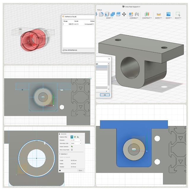
Design & Build X-axis mechanical parts:
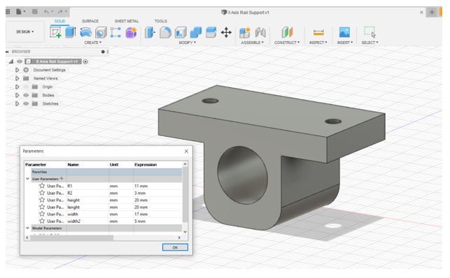
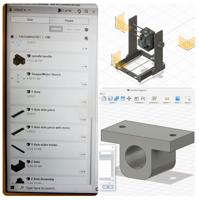
I design The linear rail shaft support, and bed sheet design using fusion 360, I started my design by setting the parameters, to editing the sizes later on according to the requirements.
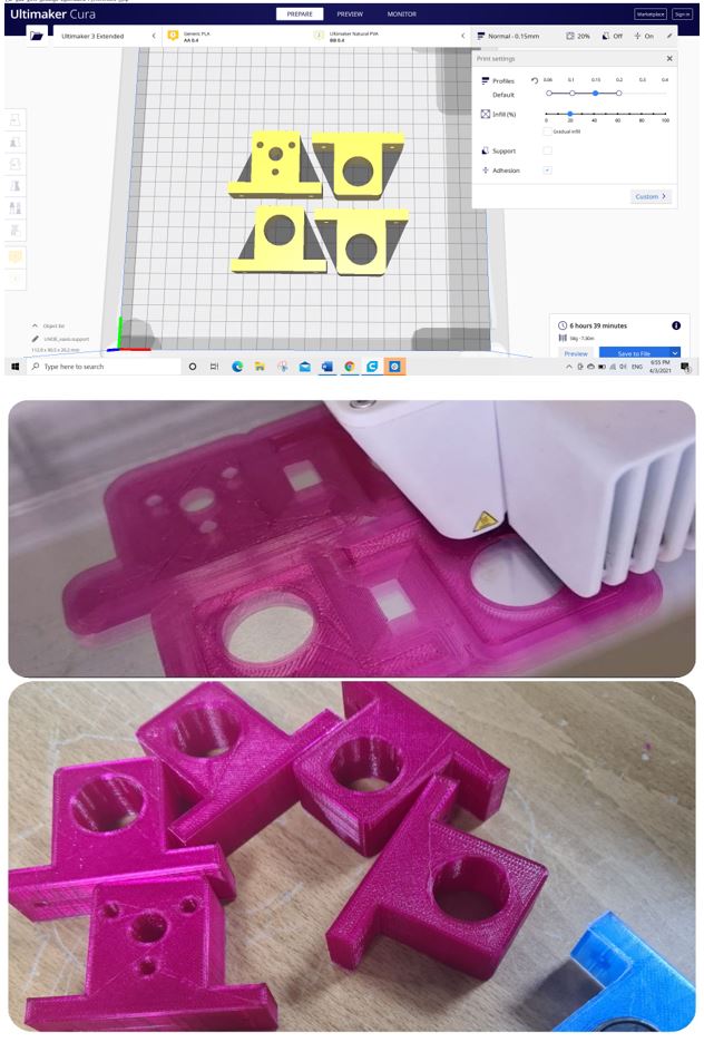
Then upload the parts to Cura and 3D printing using Ultimaker 3
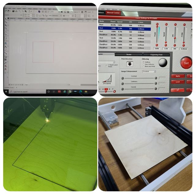
Designing the bed sheet was a piece of cake. Then cutting it using 3mm MDF sheet with Universal Laser PLS6MW Laser, settings the power= 100%, speed=2.6%, PPI=300
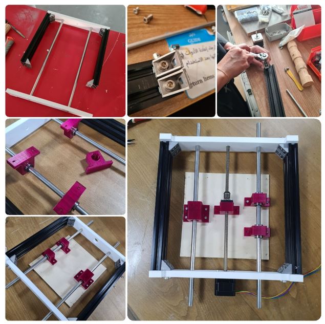
Assembling:
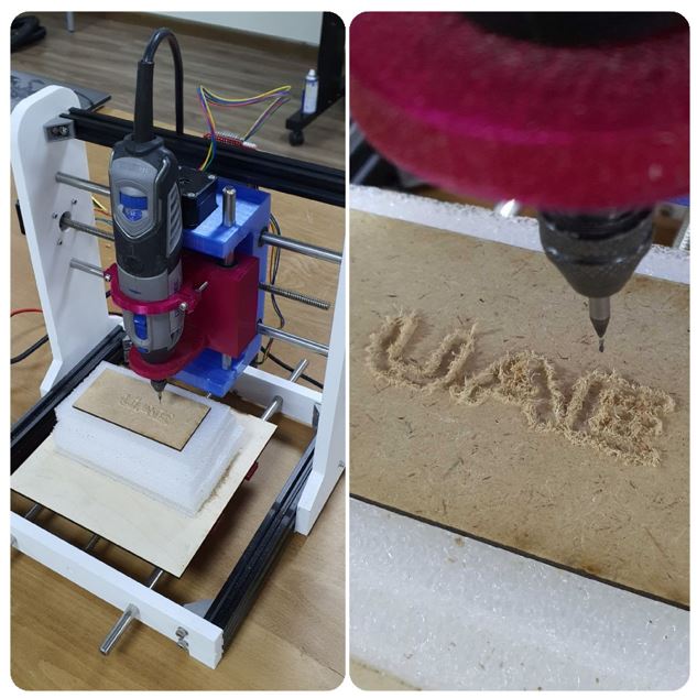
Then there was the process of screwing and assembling all the designed elements together. All the group members contribute in assembling the machine, I assembled the X-axis.
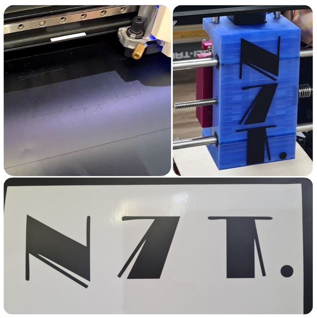
Machine Branding:
Our machine brand name is (N7T) which is Arabic name for (carving) writing in Arabic Internet Chat Language.
I used our Vinylcutter to cut the brand name and stick it on the machine.
Machine Video Production:
We recorded our journey in creating the CNC Carving Machine, then I edited the videos and produce the below video.
Challenges:
In the beginning I faced a problem with uploading my design in the group project in fusion 360 because my account didn't allow me to access this feature. Therefore, I make another account to access the group project.
After finishing my design, the X-axis linear rail shaft support, Eng.Mohammad tried to assembled all the parts but there were two issues:
1- Bearing is not fitting in the support
2- the support shorter than the Y-axis which will affect the movement of the X-axis
I solved this issue by changing the parameters of the design, it is very important to set all the parameters before designing it will save alot of time.
Finally let me introduce you to our CNC Carving Machine (N7T)