Group assignment
(Link)In this Group assignment we will compare the programs of various programming languages and programming environments as possible.
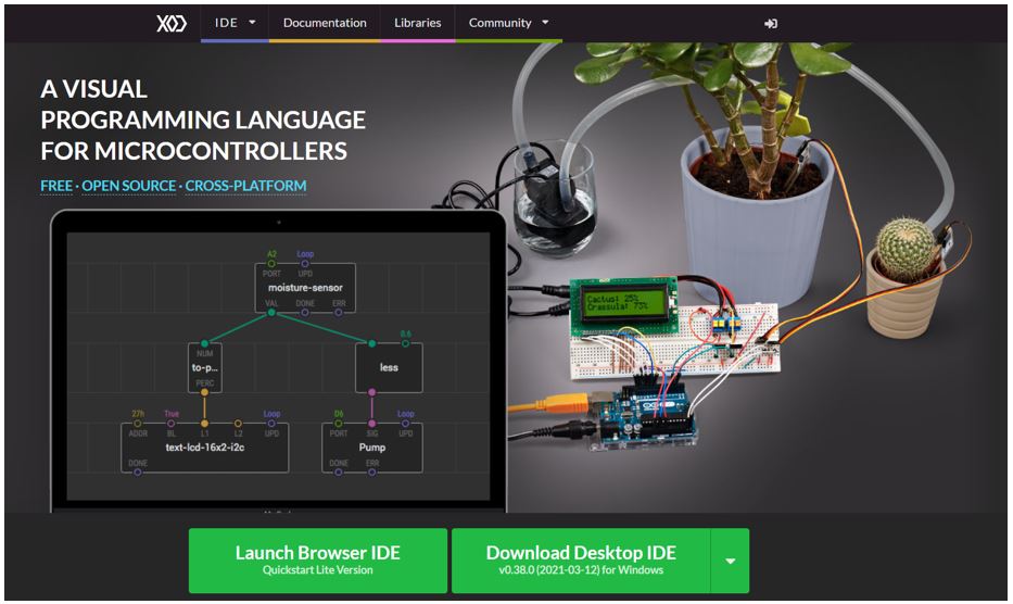
I used XOD which is a visual programming environment that enables you to program an Arduino without writing any code by only manipulate objects called “nodes” in a wide working area that's called a “patch” that can includes one or more patches. Once your program is finished you deploy it to the Arduino as if you are using the Arduino IDE. Therefore, XOD is ideal for ppl who don’t know how to write a code to be able to rapidly develop Arduino projects if you have an idea in mind and don’t want to be stuck writing the software.
What I like:
•visual programming environment
•free open-source
•the connection shown in clear path flow
•easy to learn & use
what missing:
•not supporting attiny microcontroller
Individual assignment
This week is continuing of our learning path of Week6: Electronics Design we will be programming the board we design.
1. read a microcontroller data sheet
Datasheets are essentially the manuals for electronic components. They are the key to figuring out how to use a component and to make sure it will work. Therefore, we have to know how to read this complicated fellow, while searching I found a great page the give simple steps for embedded programming & reading Datasheets. (5 Steps to Getting Started with Embedded Programing)
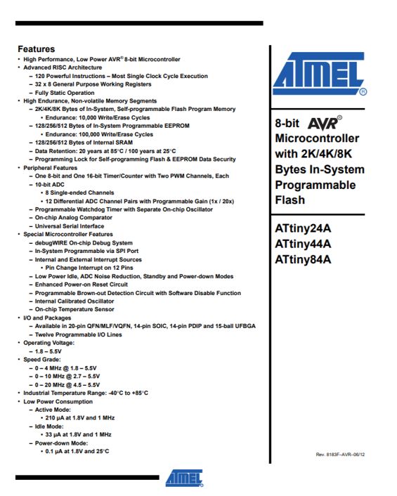
DATASHEET FOR ATTINY44: The primary page is typically a summary of the part’s function and features. this can be where you'll quickly find an outline of the part's functionality, the essential specifications and sometimes a functional diagram that shows the central functions of the part. This page will often offer you a decent first impression on whether potential part will work for your project or not.
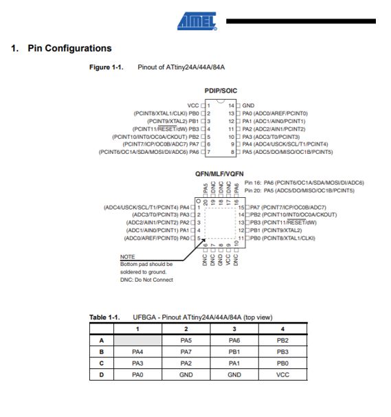
A pinout lists the part’s pins, their functions, and where they’re physically located on the part for various packages the part might be available in. Notice the distinct marks on the part to define where pin 1 is (this is very important after you plug the part into your circuit!), and the way the pins are numbered.
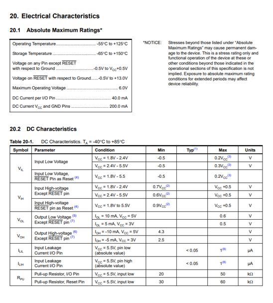
Detailed tables of electrical specifications follow. These will frequently list the maximum ratings that shouldn’t be exceeded for a component or it will be damaged. You'll also see the more normal recommended operating conditions. These may include voltage and current ranges for various functions, and other useful performance information.
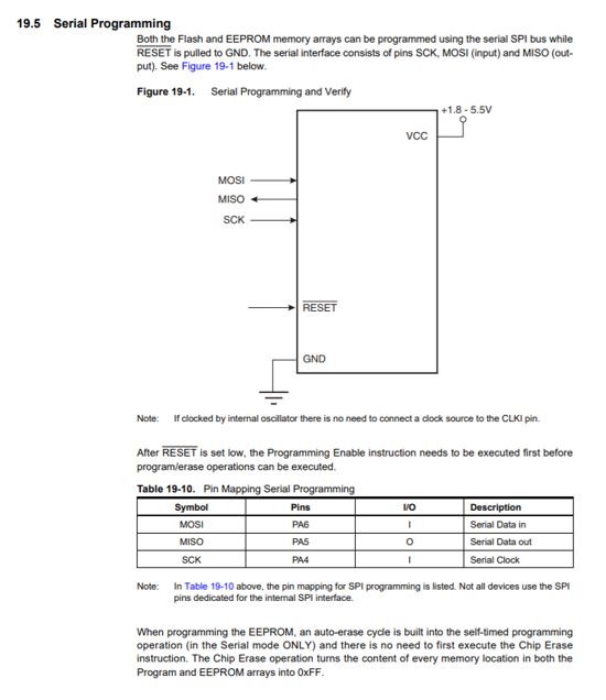
During our lessons previous weeks, we can briefly touched on how to program our 'hello world' board. Using the ISP (2x3) cable to program the AVR chip, we want to map to those six pins (VCC, GND, MOSI, MISO, RESET and SCK).
So to sum it up A datasheet is the best place to find what voltage a part needs to run, how fast a part will run, and how to communicate with a part.
2.Program your board to do something
ATtiny 44 Hello echo board programming
Hardware require :
Programmer (ISP) : FabTinyISP (that I design on week4)
Target Board : Hello World board
Cable : Ribbon Connecter
Step 1: first download Arduino IDE 1.8.13
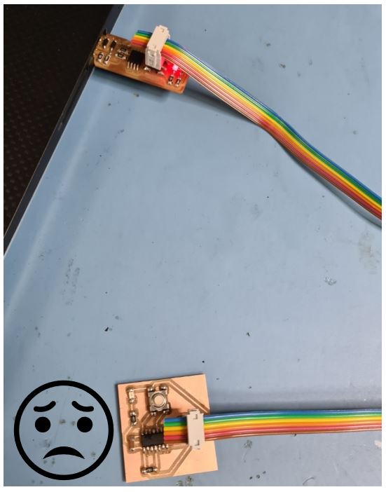
Step 2: insert the FabTinyISP in the PC and connect it with my PCB through ribbon connector.
Step 3: open Arduino IDE then add ATtiny44 in the software through File > Preferences > go down to Additional Boards Manager URLs > paste the following URL “https://raw.githubusercontent.com/damellis/attiny/ide-1.6.x-boards-manager/package_damellis_attiny_index.json” > Ok
Step 4: Tools> Programmer>Set Programmer to "USBTinyISP"
Step 5: Tools > Board> ATtiny Microcontrollers > ATtiny24/44/84
Step 6: Tools > Processor > ATtiny44
Step 7: Sketch > Upload Using Programmer
Step 8: Tools > Burn Bootloader
Step 9: Open an Aurdino example on "Blinking LED" and modify from there. lunch the default Arduino example to blink the led to check if the toolchain working.
Step 10: Then alter the code number within the pin that connected to the LED according to the schematic design by using the layout shown below to map Arduino PINs.
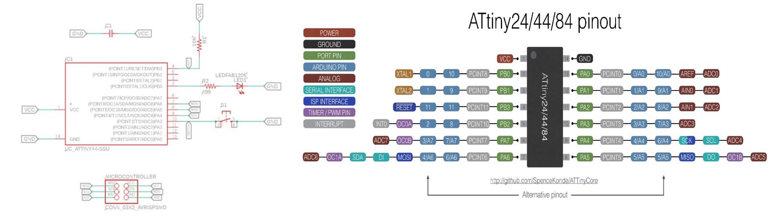
the code I used & modified is as following, the code explained in each code line.
/*
  Blink

  Turns an LED on for one second, then off for one second, repeatedly.

  Most Arduinos have an on-board LED you can control. On the UNO, MEGA and ZERO
  it is attached to digital pin 13, on MKR1000 on pin 6. LED_BUILTIN is set to
  the correct LED pin independent of which board is used.
  If you want to know what pin the on-board LED is connected to on your Arduino
  model, check the Technical Specs of your board at:
  https://www.arduino.cc/en/Main/Products

  modified 8 May 2014
  by Scott Fitzgerald
  modified 2 Sep 2016
  by Arturo Guadalupi
  modified 8 Sep 2016
  by Colby Newman
modified 24 Mar 2021
  by Ohood Walid


  This example code is in the public domain.

  https://www.arduino.cc/en/Tutorial/BuiltInExamples/Blink
*/

// the setup function runs once when you press reset or power the board
void setup() {
  // initialize digital pin LED_BUILTIN as an output.
  pinMode(10, OUTPUT);
}

// the loop function runs over and over again forever
void loop() {
  digitalWrite(10, HIGH);   // turn the LED on (HIGH is the voltage level)
  delay(1000);                       // wait for a second
  digitalWrite(10, LOW);    // turn the LED off by making the voltage LOW
  delay(1000);                       // wait for a second
}
Step 11: Click the 'Verify/Compile' button to check your code. This button check and compile your code.
Unfortunately, it didn’t work. Time to search for the problem >_<
With the help of our instructor Eng.Waleed he highlight the issue was because of the resistor I put the wrong one, therefore, I removed it then I soldered the right resistor
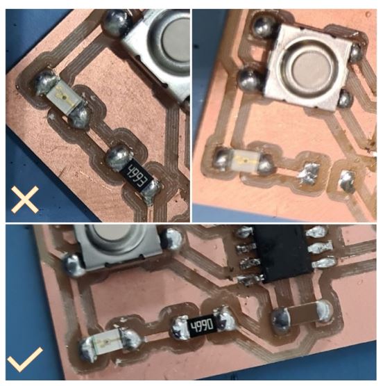
Then repeating the previous steps & finally it worked
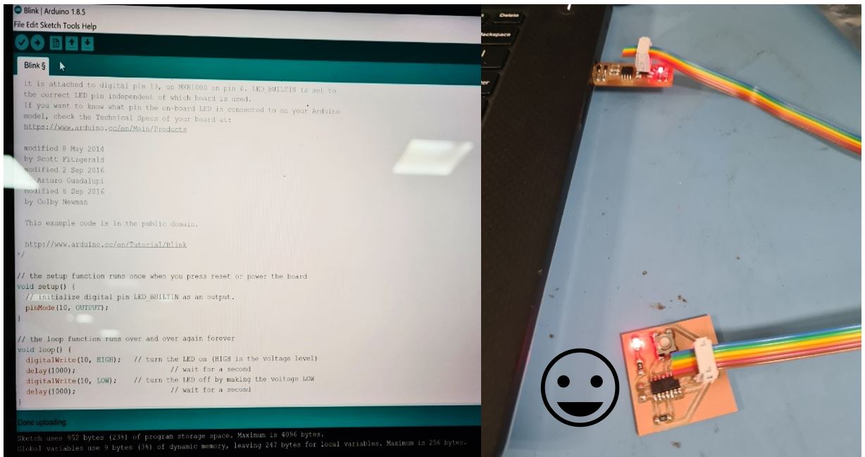
video shows my board working
(XOD) visual programming Language
exploring different programming languages, I used XOD.
XOD is a free open-source visual programming environment that enables the user to program an Arduino without writing any code by only manipulate objects called “nodes” in a wide working area that's called a “patch” that can includes one or more patches. Once the program is finished then deploy it to the Arduino as if using the Arduino IDE.
Therefore, XOD is ideal for ppl who don’t know how to write a code to be able to rapidly develop Arduino projects if you have an idea in mind and don’t want to be stuck writing the software.
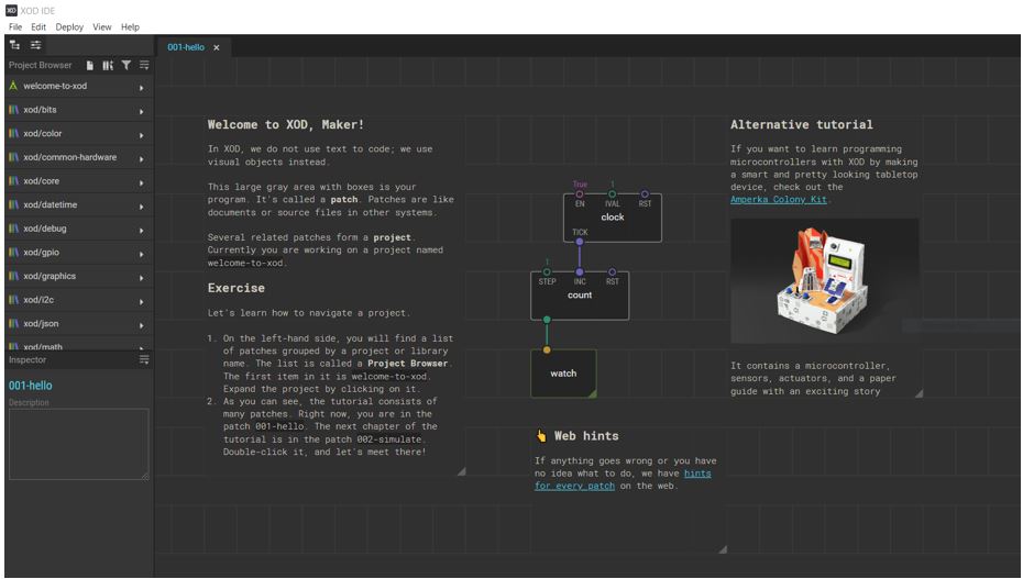
First, I download the program from this link, then I used this websiteto guide me through XOD. Then I lunched the XOD & follow the tutorial to have an idea how to use it.
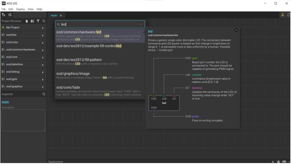
Then I opened a new project from file menu, then I double click on the patch area & write Led to search and insert the led nodes in the working area “patch”
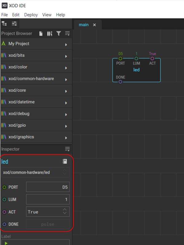
To start programming I connected the board to my computer, then change the value that shown in the red box below by adding the digital port for the led. Then change the value of tweak-number in the range from 0 to 1 to switch on or off the led.
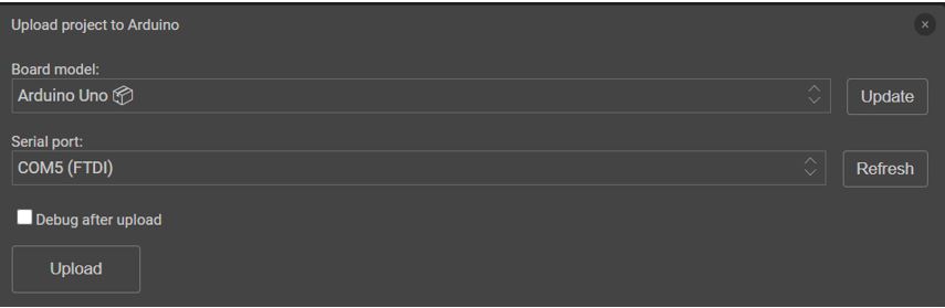
From the main menu click Deploy > Upload to Arduino.
Then chose Arduino uno for the board model and the port then click on Upload.
It is working very simple and easy as shown in the video below, I’d like to thank the person who develop this program that make the life easy.