Individual assignment
This week we learned how to use Eagle CAD to PCB Design.
I download Eagle CAD but I faced some difficulty in lunching EAGLE so I tried to uninstall it then reinstall EAGLE still no use :(
so I used EasyEDA until I solve the Eagle issue. (you can find the EasyEDA documentation at the end of this page)
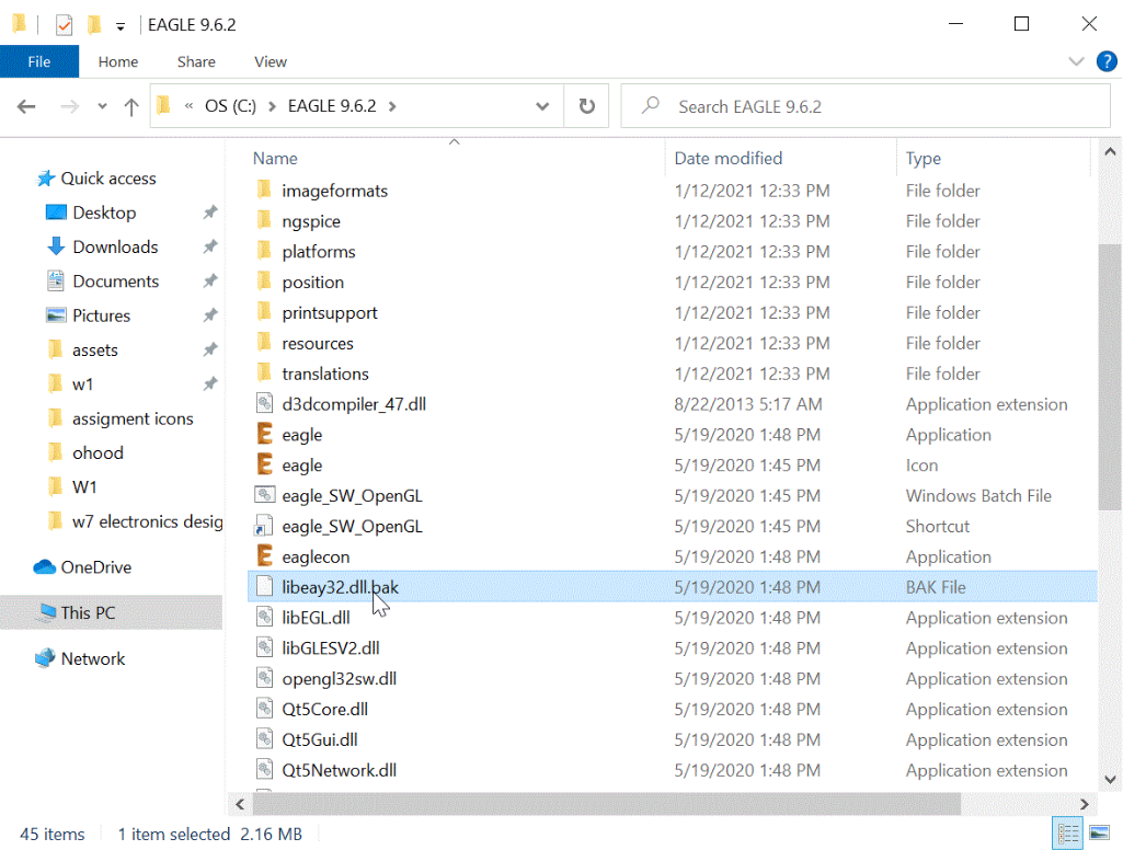
Thankfully Eng.Maha helped me in fixing the issue by going to the setup file of EAGLE in the C drive then search for a file name (libeay32.dll) & adding BAK File Extension (.bak) to retrieve the original contents of the file. Then I tried to lunching it again and it worked
Create a new project folder was the first step in creating a circuit
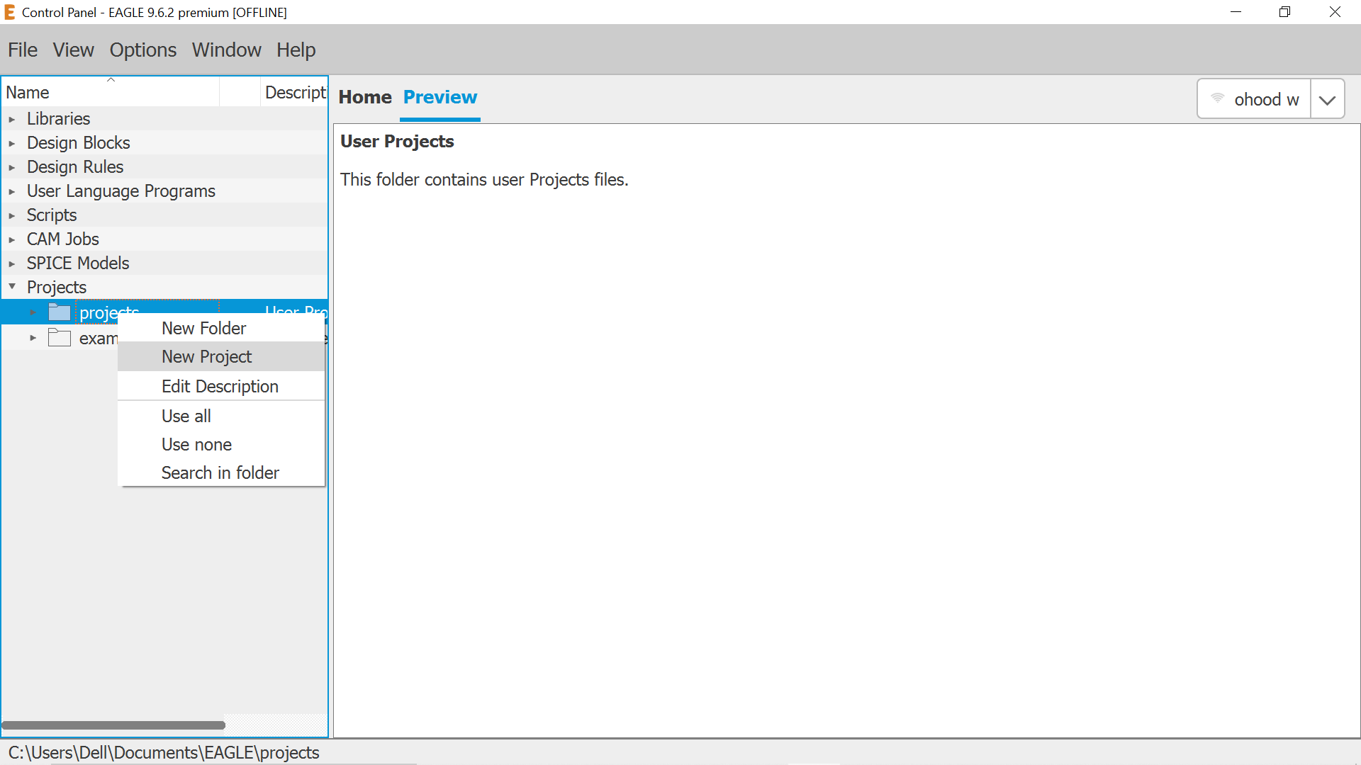
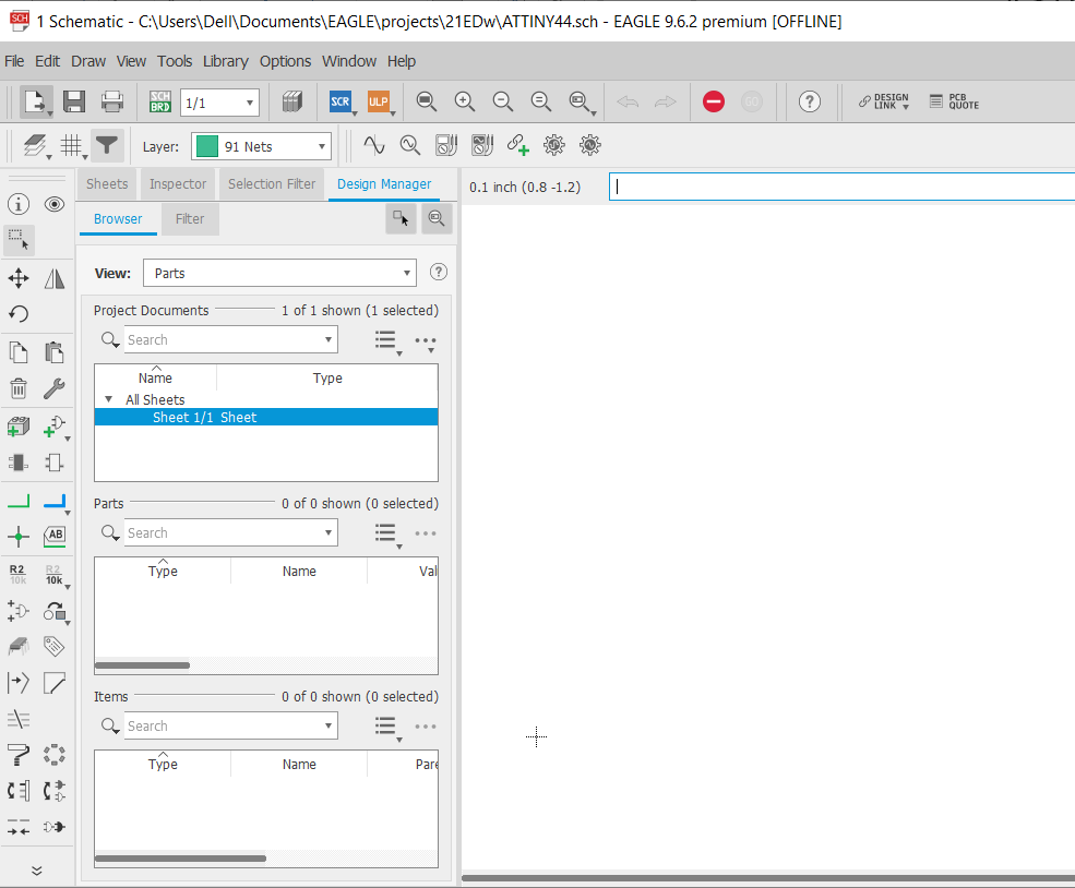
then create a new schematic project file
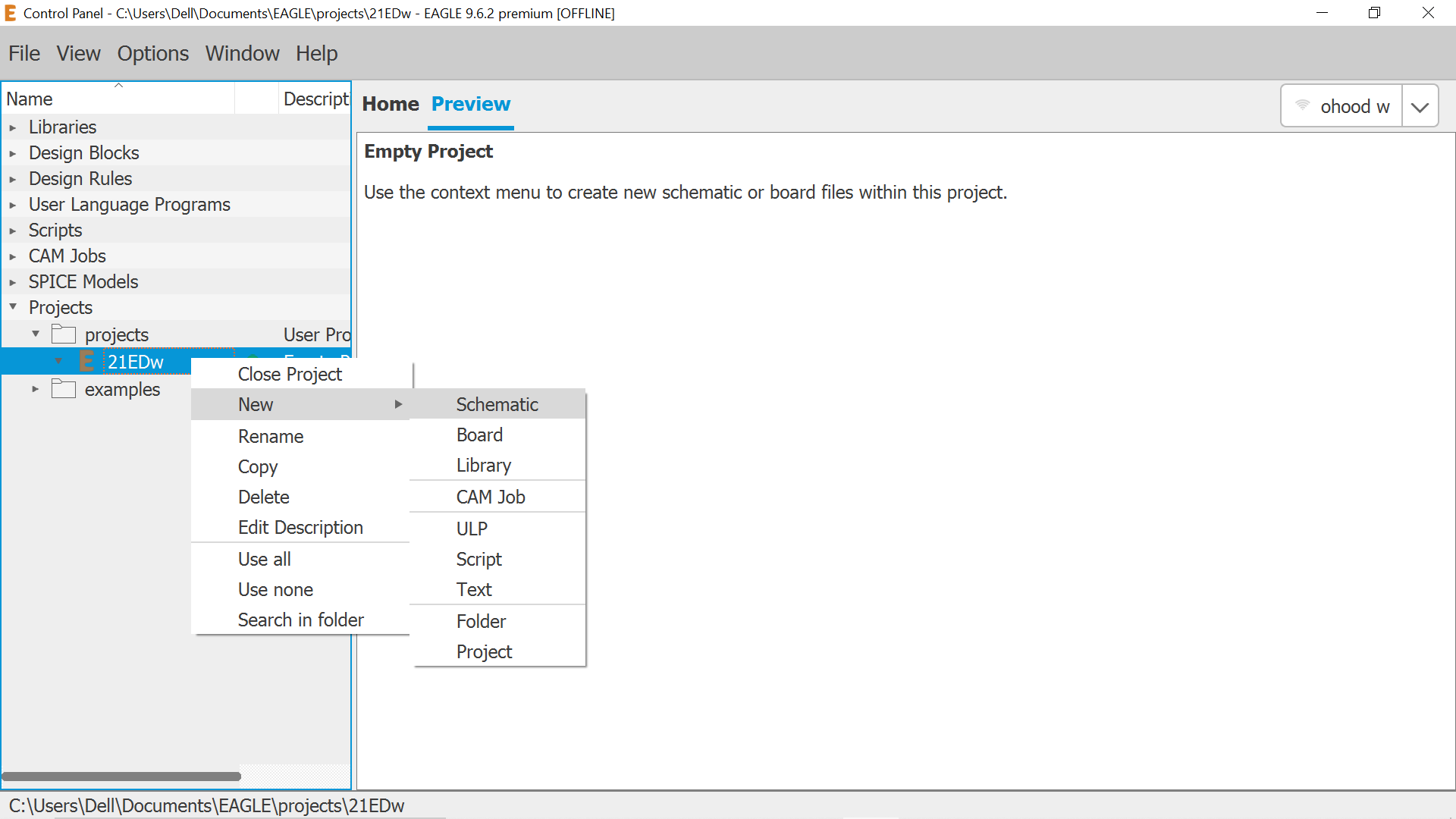
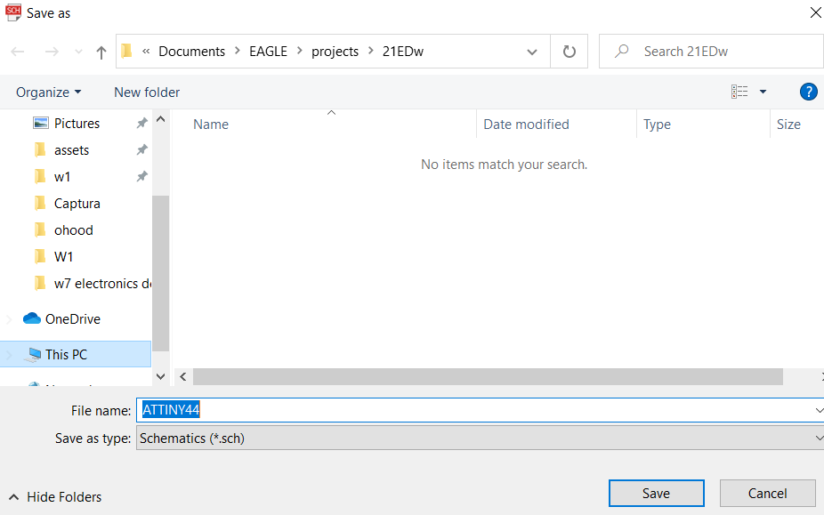
Save it
Ready to draw
to start designing my electronic circuit first I download the library to have all the required files such as the circuit parts by clone the electronics library provided by FabAcademy
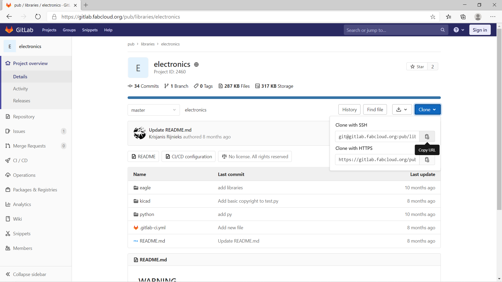
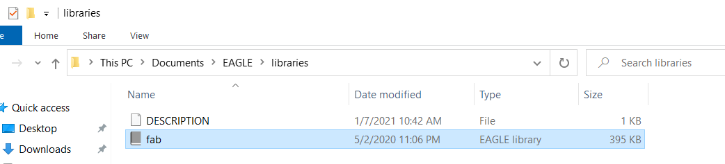
Then add the file (fab) to EAGLE library
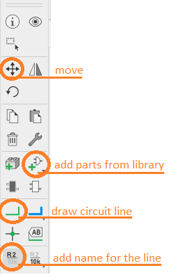
then circuit creation started by using the following navigation bar
Added ATTINY44 from library
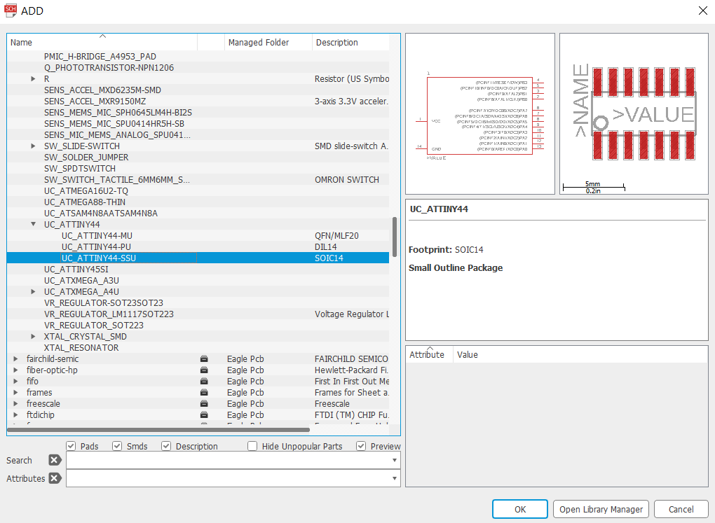
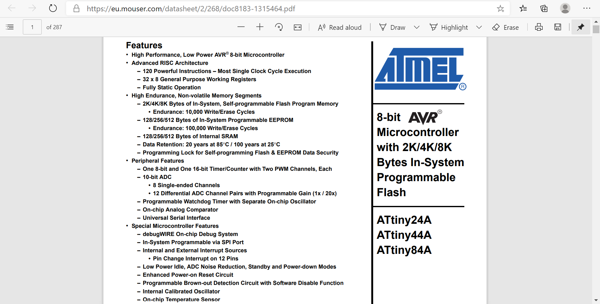
Following Eng. Hashim advice, I searched the datasheet for ATTINY44 to know more about it
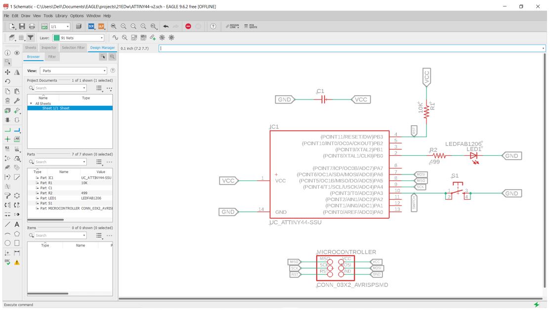
Then I started to draw the attiny44 board include one LED with current limiting resistor
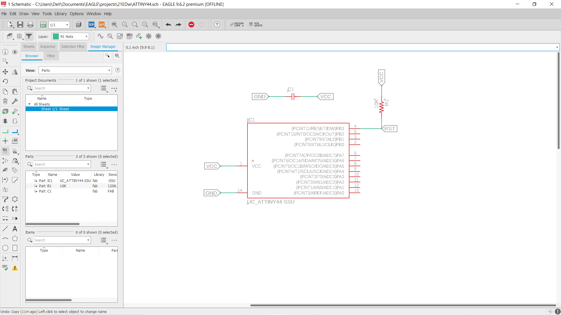
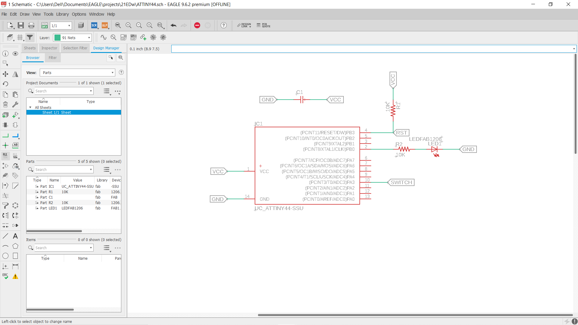
Adding the microcontroller & linked it to ATTINY44. Also adding some different inputs and outputs such as (on/off switch & LED light) and link it to the circuit.
after I created the schematic, it’s time to switch our view to board with the button on the top left (Generate/switch to board)
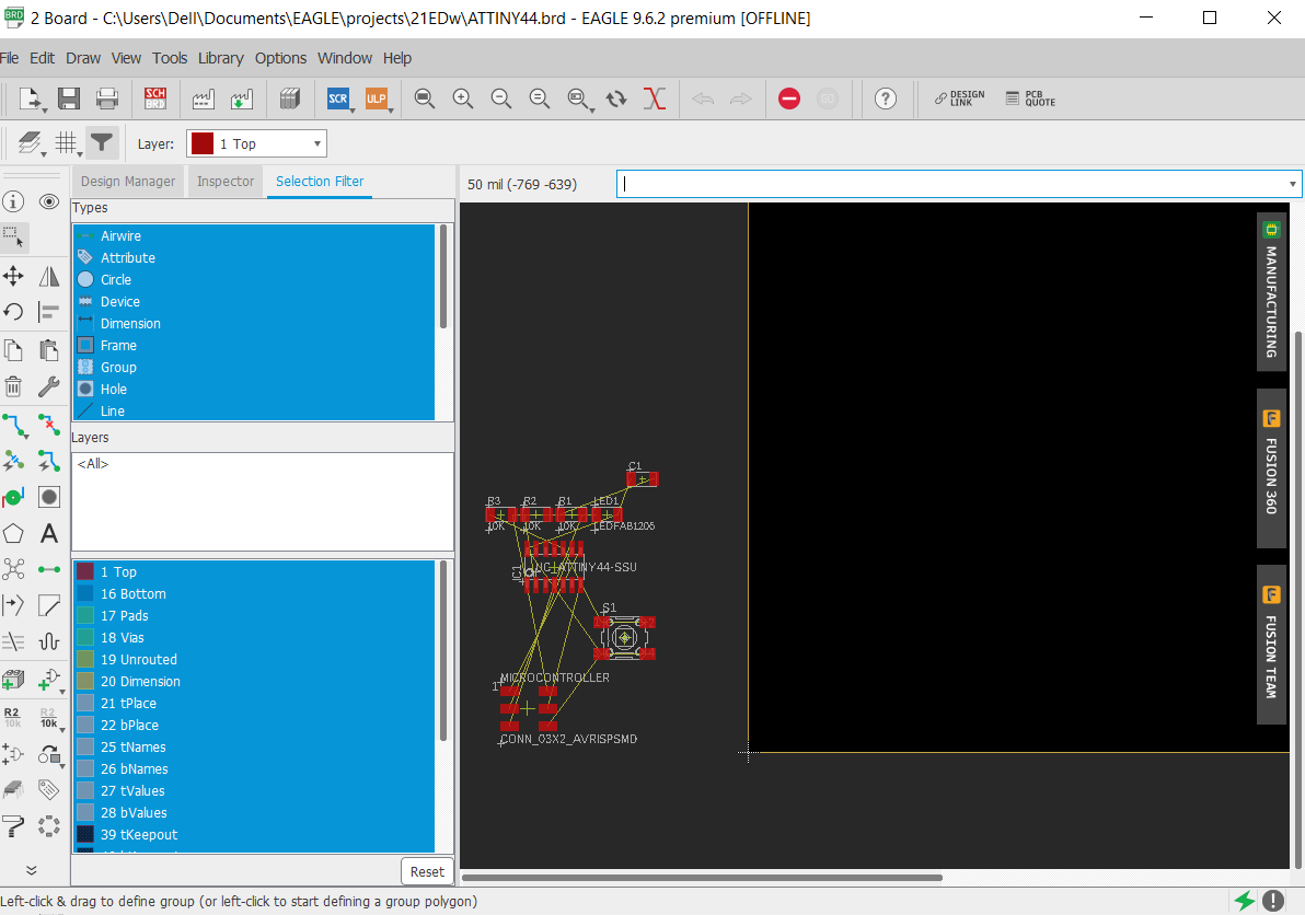
I reorganized the parts & connected them by using (Route Airwire) tool on the left bar
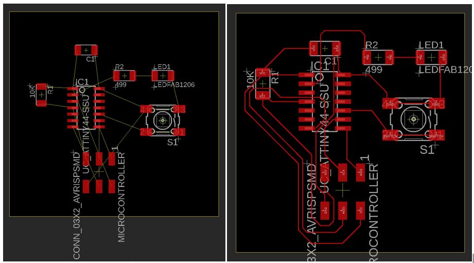
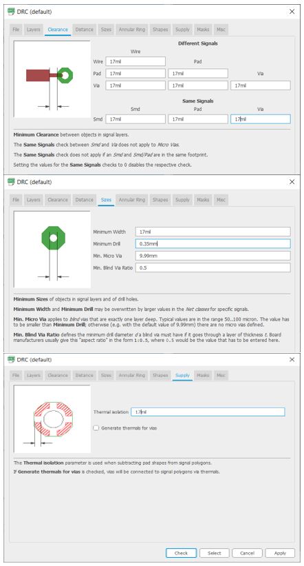
Unfortunately, I didn’t adjust the DRC before drawing so I have to delete all the Route Air wire & draw again after editing the following as shown below:
(Clearance, Sizes, & supply) > 17mil
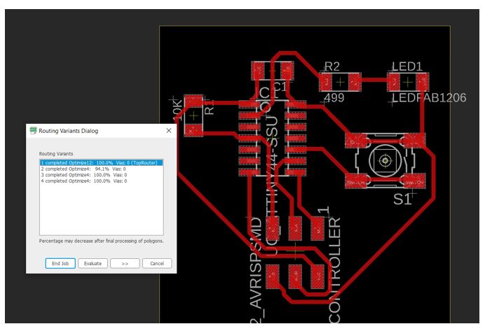
Trying “Auto Routing” was useful but I had to redraw some lines.
To save the traces follow the below steps:
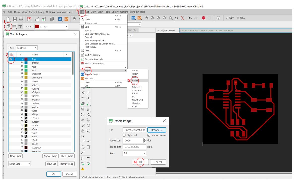
Open “Visible Layers” & select all then hide all the layer > show only “Top” layer
Open “File” > Export > Image PNG
Click “Browse” to choose the location > select “Monochrome” > Resolution= 2000dpi > OK
Repeat the steps to save the Outline (Dimension)
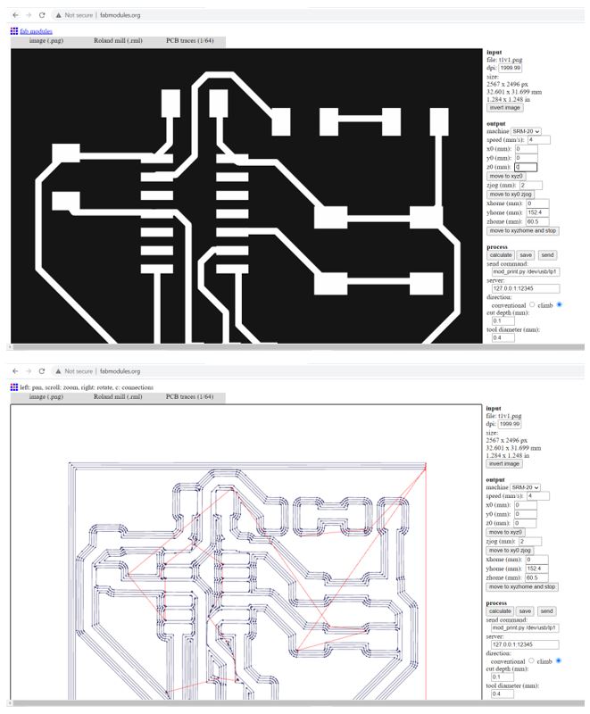
Then upload the image in fab modules to convert the files to (.rml) following these steps
1-Traces: Upload image .png > chose machine “Roland mill” > PCB traces (1/64) > Machine= SRM-20 > X0, Y0, Z0 = 0 mm > calculate > Save
2-Outline: Upload image .png > chose machine “Roland mill” > PCB outline (1/32) > Machine= SRM-20 > X0, Y0, Z0 = 0 mm > calculate > Save
Roland SRM-20 was used to mill the PCB board, the milling wasn’t good it was shallow (the copper wasn’t removed properly) so I increase the cut depth.
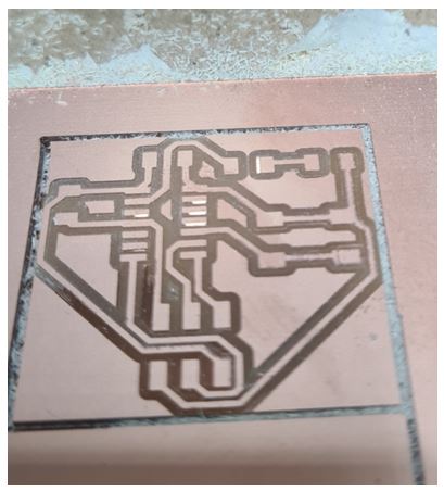
The second milling was much better, then soldering the components in the correct orientation
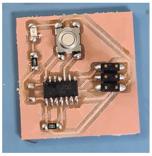
Done with the soldering then using multimeters to check the connectivity of PCB
this is a video that shows my board is working
EasyEDA
I download Eagle CAD but I faced some difficulty in lunching EAGLE so I search for another solution and I found this website
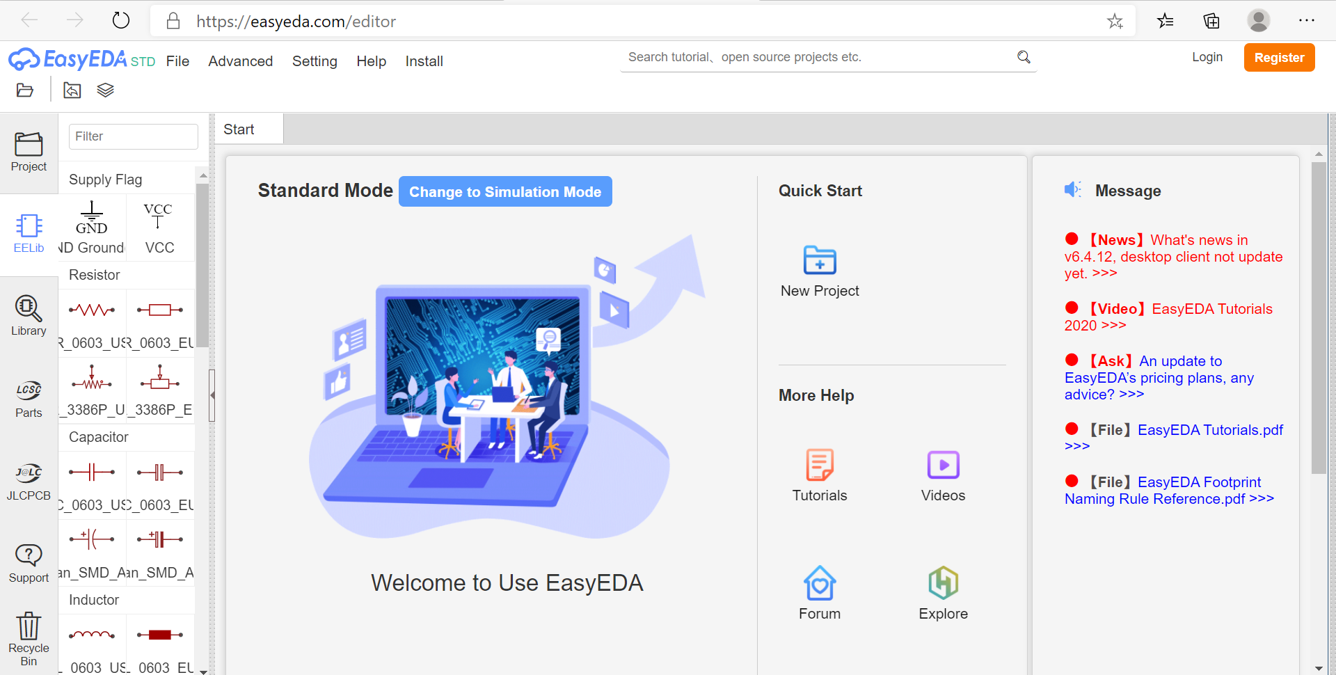
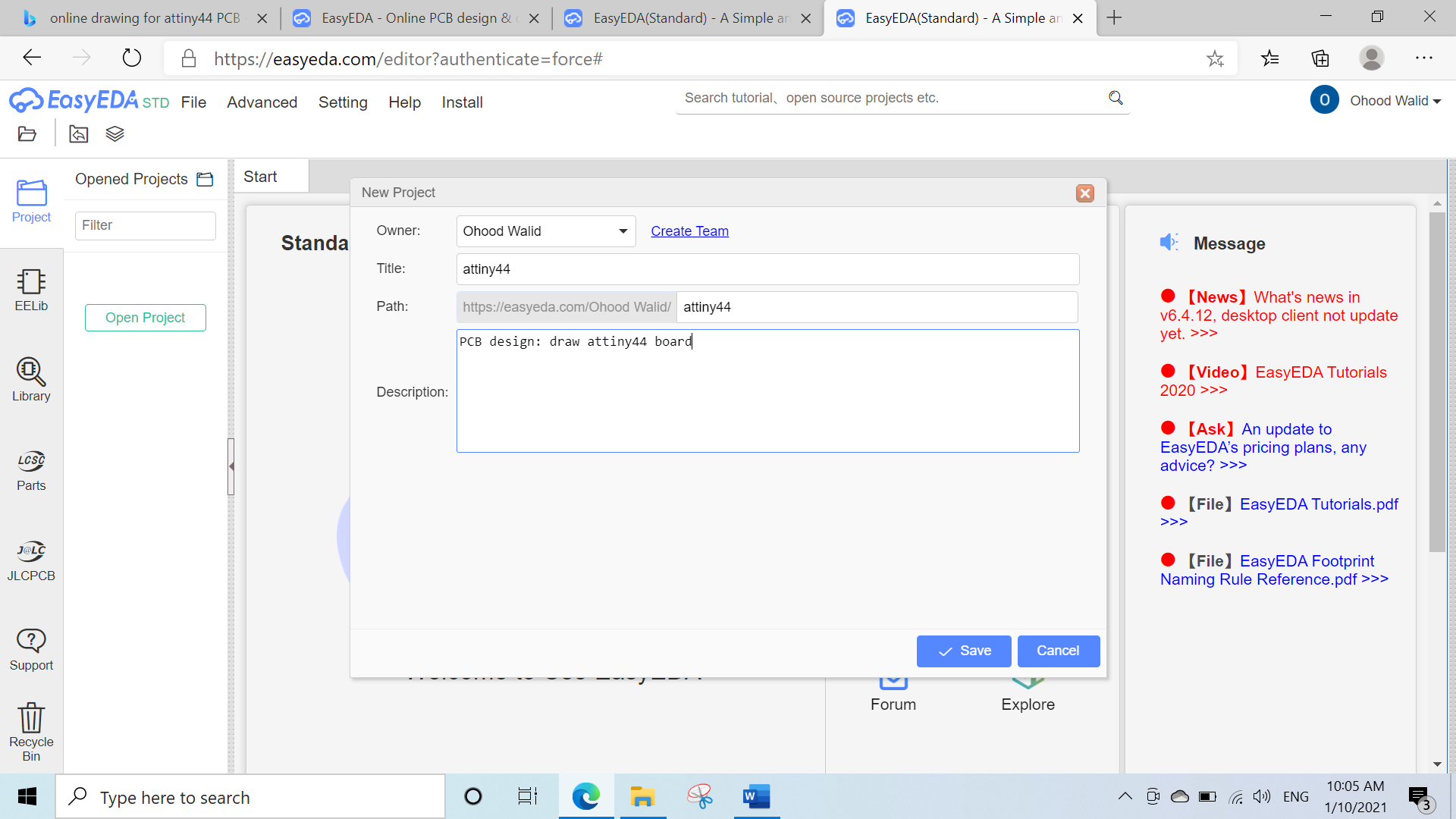
I started by creating a new project
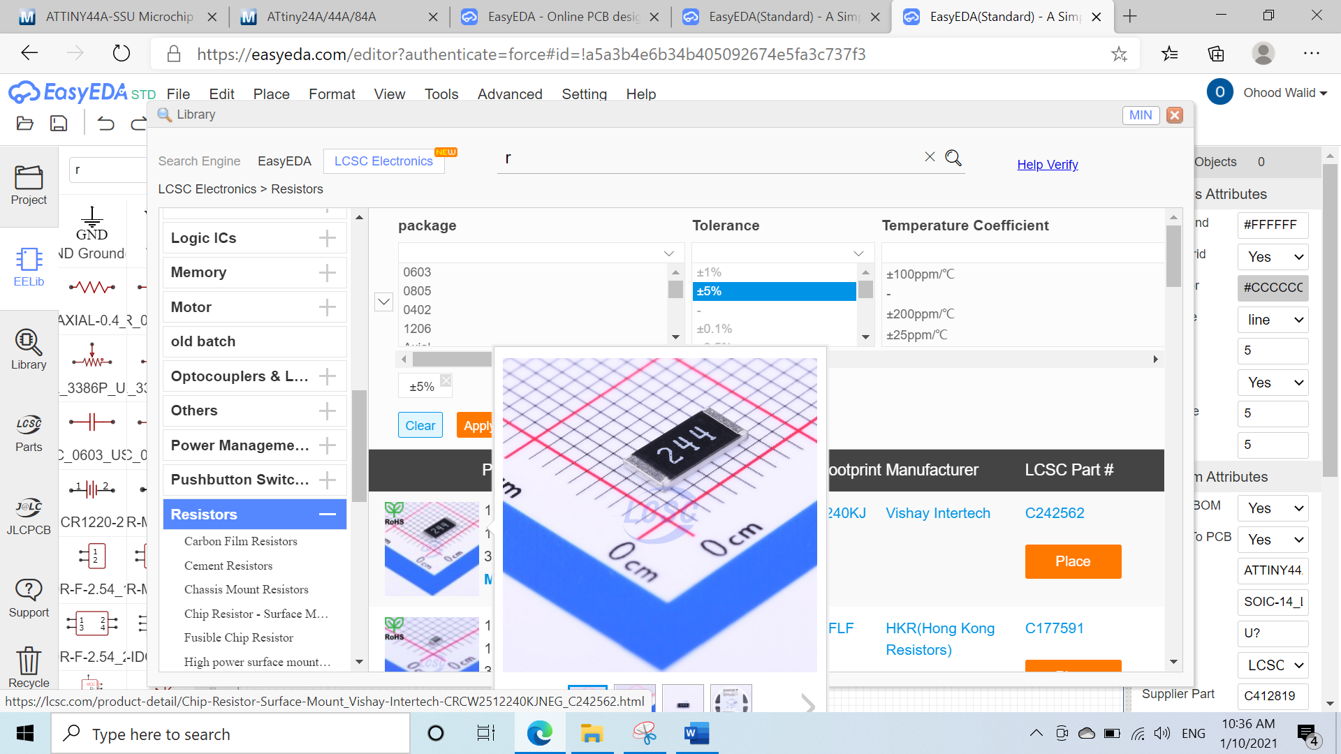
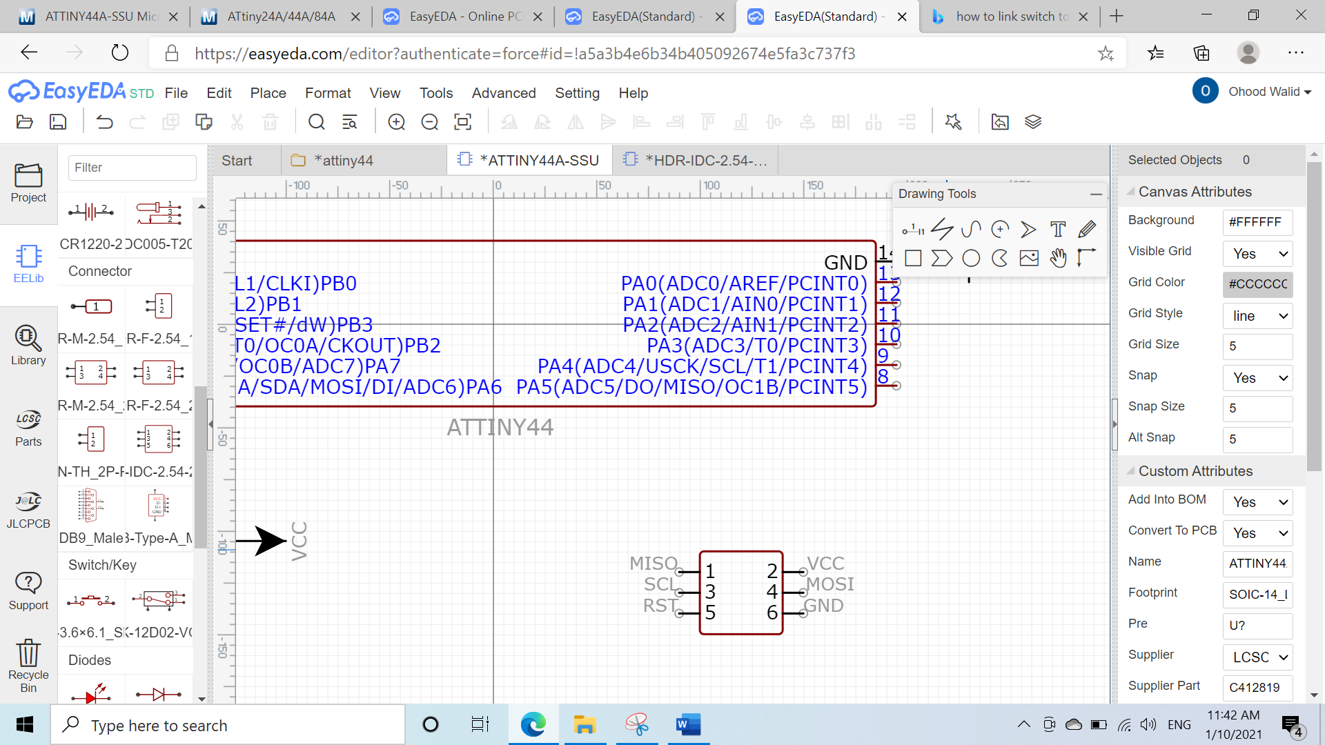
Then I chose ATTINY44 from the library in the left options
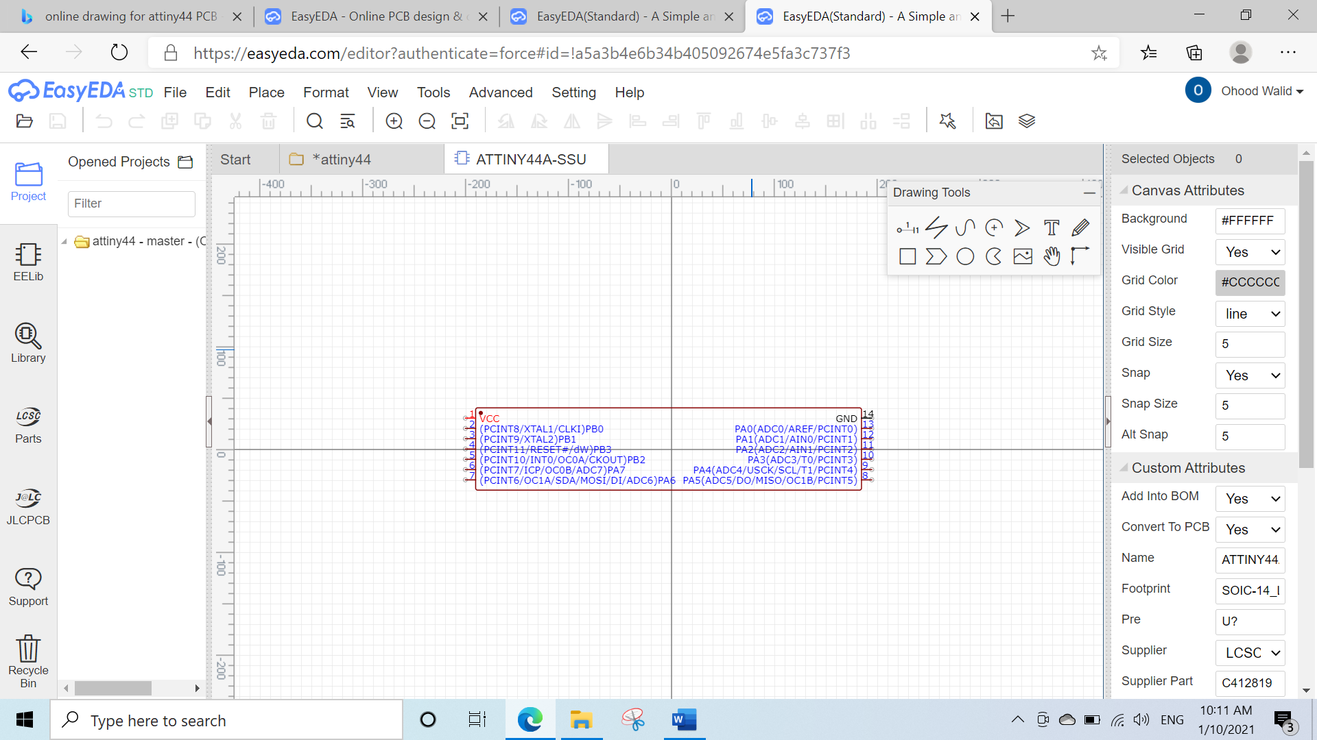
This website provides all information about all the electronics parts
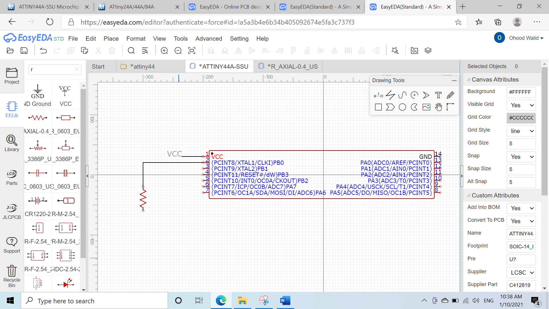
Then I started to redraw the attiny44 board include one LED with current limiting resistor and one button by navigating through the bars shown below
EELib= scroll through to select the electronics parts
Drawing Tools= tools to draw the electronic circuit
Selected Objects= to edit the attributes of selected electronics parts
R-click= rotate the objects

Adding the current limiting resistor
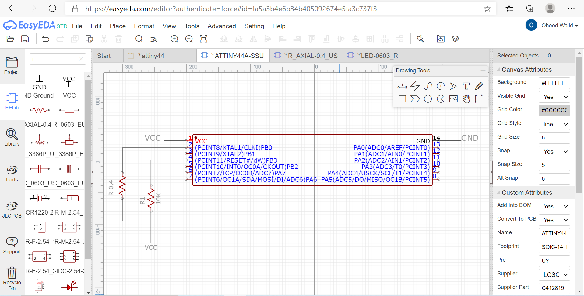
Then adding the LED
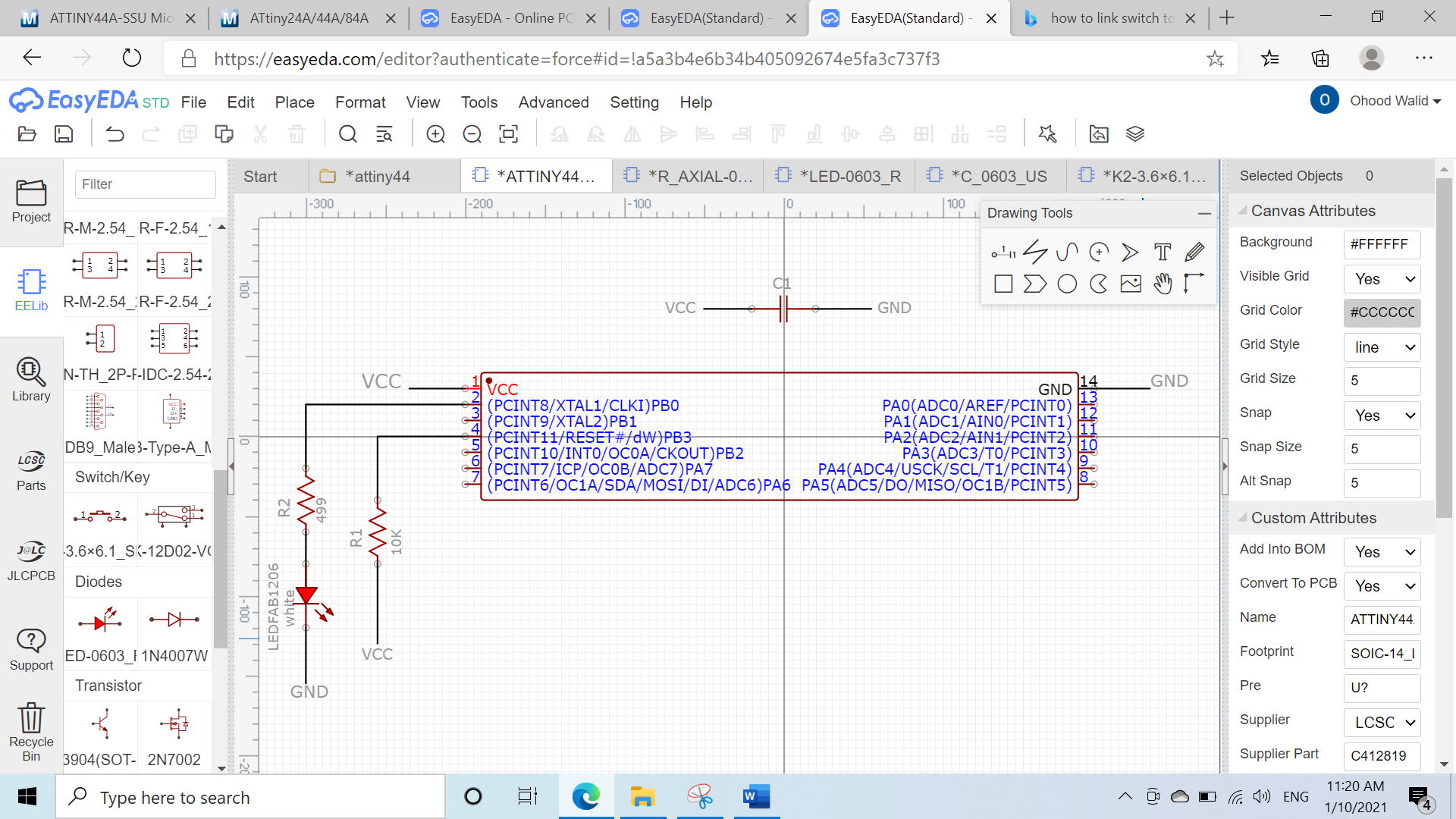
Drawing the switch
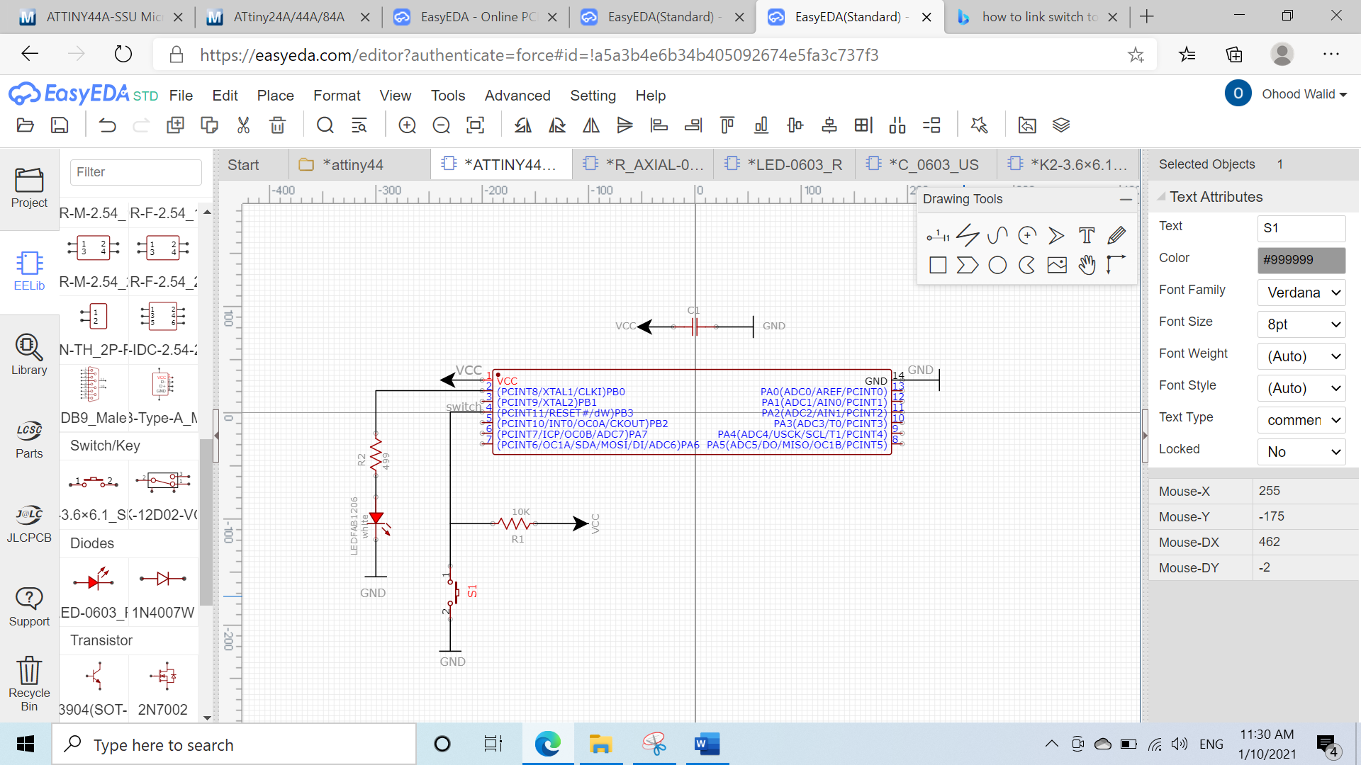
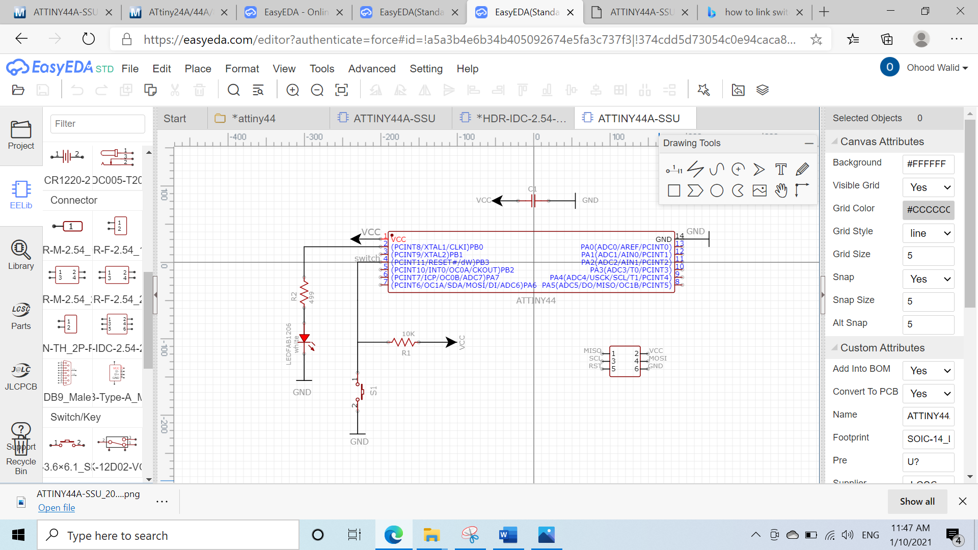
Then I draw the source programmer & added the links names
I completed the drawing of the circuit
Group assignment
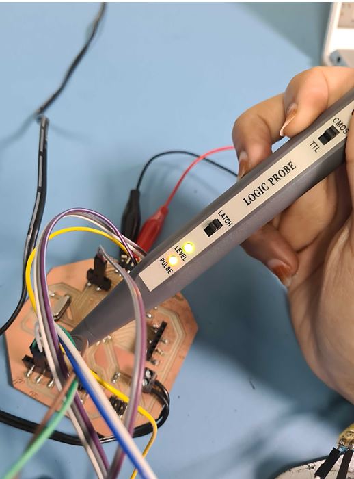
(Link)In this week group assignment, I’m measuring & testing the input digital circuits using Logic Probe measurements tool.
The logic probe one of the low-cost tools that easy to use help in testing the digital circuits with very basic information.
So if the green light appear it mean that that the logic high which state that it is able to detect digital pulses as shown when I tested the digital flow in my board.
also I used multimeters to check the connectivity of my PCB