Group assignment
(Link)our group assignment is to measure the power consumption of our board after connecting with all the outputs. I used WANPTEK machine which is a adjustable DC voltage regulated power supply to measure my ATMEGA328P board connected with the screen, buzzer, and led.
then using this equation (P=IV):
Power = Voltage X Current
Power = 5 X 0.1
Power = 0.5 watts
Individual assignment
This week is continuing of our learning path of Week6 & Week8. I will be programming diffrent example of outputs as following.
LED
Lunch Arduino IDE 1.8.13
insert the FabTinyISP in the PC and connect it with my PCB through ribbon connector.
go to Tools> Programmer>Set Programmer to "USBTinyISP"
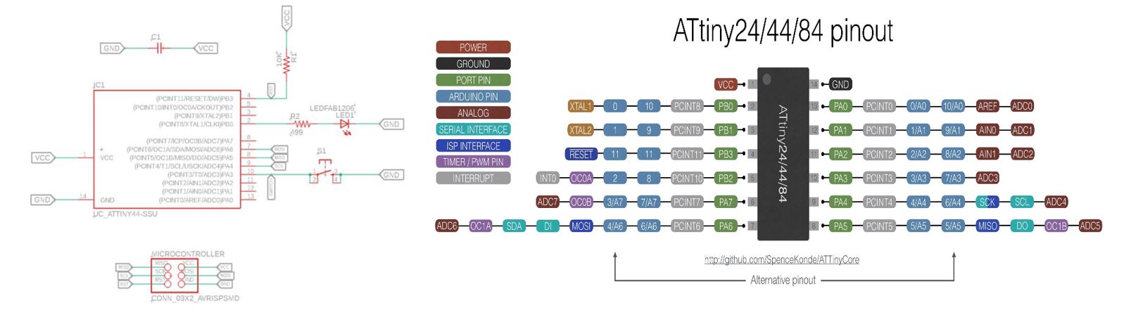
go to Tools > Board> ATtiny Microcontrollers > ATtiny24/44/84
go to Tools > Processor > ATtiny44
Then write the code to turns on the LED controlled by pushbutton I got the code from this link
/*
  Button
*/

// constants won't change. They're used here to set pin numbers:
const int buttonPin = 3;     // the number of the pushbutton pin
const int ledPin =  10;      // the number of the LED pin

// variables will change:
int buttonState = 0;         // variable for reading the pushbutton status

void setup() {
  // initialize the LED pin as an output:
  pinMode(ledPin, OUTPUT);
  // initialize the pushbutton pin as an input:
  pinMode(buttonPin, INPUT);
}

void loop() {
  // read the state of the pushbutton value:
  buttonState = digitalRead(buttonPin);

  // check if the pushbutton is pressed. If it is, the buttonState is HIGH:
  if (buttonState == HIGH) {
    // turn LED on:
    digitalWrite(ledPin, HIGH);
  } else {
    // turn LED off:
    digitalWrite(ledPin, LOW);
  }
}
Mapping ATTiny44 Pin with Arduino PIN number by refering to the 'Arduino and ATTiny Pin Layout Diagam' shown below & alter the code number in the pin that connected to the LED according to the schematic design, then go to Tools > Burn Bootloader Then Sketch > Upload Using Programmer
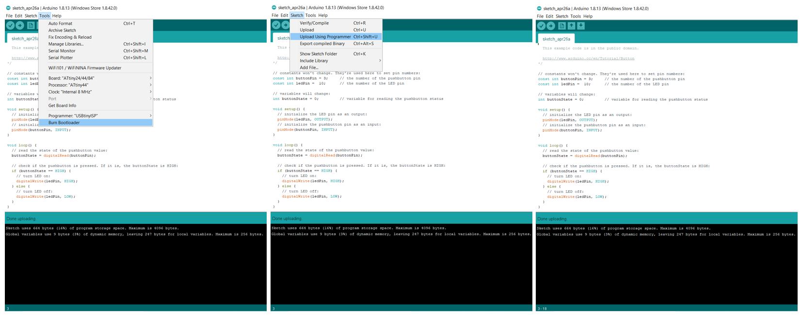
it worked successfully
Wave project outputs
In this example my outputs are screen, buzzer, led. The screen to show the real time with notification when the alarm activated, also the buzzer & led work when the alarm activated.
I will start programming the RTC following the steps from this link. I will be explaining the code.
First, I need to mention the libraries I added in the code as following
#include <DS3231.h>  //RTC library
#include <Wire.h> //I2C communication
#include <Adafruit_GFX.h>  //LCD
#include <Adafruit_SSD1306.h> //LCD library
Then add the code for the LCD that display the real time (output)
#include <Adafruit_SSD1306.h> //LCD library
#define SCREEN_WIDTH 128 // OLED display width, in pixels
#define SCREEN_HEIGHT 64 // OLED display height, in pixels
Then specified the variable that I will use in the code and for an SSD1306 display connected to I2C, Also specified the buz pin & led pin from checking my board diagram
Adafruit_SSD1306 display(SCREEN_WIDTH, SCREEN_HEIGHT, &Wire, -1);
DS3231  rtc(SDA, SCL);
Time  t;
#define buz 6
#define Led 7
int Hor;
int Min;
int Sec;
Then I set the date & time for the RTC, also this setting will be written once because the RTC has a battery which will keep the real time even if it is not powered
void setup()

{
  Wire.begin();
  rtc.begin();

  // The following lines can be uncommented to set the date and time

  //rtc.setDOW(TUESDAY);     // Set Day-of-Week

 // rtc.setTime(19, 26, 0);     // Set the time to 12:00:00 (24hr format)

  //rtc.setDate(6, 15, 2021);   // Set the date

  //delay(2000);

}
Then in the loop I write the code to get the time from RTC and save it in the variable so I can use it when I set the alarm time.
void loop()
{
  t = rtc.getTime();
  Hor = t.hour;
  Min = t.min;
  Sec = t.sec;
To preview the time on the LCD screen I added this code
  display.clearDisplay();
display.setTextSize(2.5);
display.setTextColor(WHITE);
display.setCursor(0, 30);
// Display static text
display.print(Hor);
display.print(":");
display.print(Min);
display.print(":");
display.println(Sec);
display.display();

//display.clearDisplay();
//display.setTextSize(1);
//display.setTextColor(WHITE);
//display.setCursor(0, 10);
//// Display static text
//display.println(t);
//display.display();
digitalWrite(6, HIGH);
digitalWrite(7, HIGH);
Then I added this code to compare the current time with the alarm. So when the alarm start the screen will show the specified text “Hi, Take Med!” and the buzzer & led will start working
 if( Hor == 19 &&  Min == 39) //Comparing the current time with the Alarm time
{

Buzzer();

Buzzer();

light();

light();

display.clearDisplay();
display.setTextSize(1.5);
display.setTextColor(WHITE);
display.setCursor(0, 25);
//// Display static text
display.println("Hi, Take Med!");
display.display();

Buzzer();

Buzzer();

light();

light();

}

 delay(1000);

}
Combining all codes as following
#include <DS3231.h>

#include <Wire.h>

#include <Adafruit_GFX.h>
#include <Adafruit_SSD1306.h>

#define SCREEN_WIDTH 128 // OLED display width, in pixels
#define SCREEN_HEIGHT 64 // OLED display height, in pixels

// Declaration for an SSD1306 display connected to I2C (SDA, SCL pins)
Adafruit_SSD1306 display(SCREEN_WIDTH, SCREEN_HEIGHT, &Wire, -1);


DS3231  rtc(SDA, SCL);

Time  t;

#define buz 6
#define Led 7

int Hor;

int Min;

int Sec;

void setup()

{
if(!display.begin(SSD1306_SWITCHCAPVCC, 0x3C)) { // Address 0x3D for 128x64
    Serial.println(F("SSD1306 allocation failed"));
    for(;;);
}
  Wire.begin();

  rtc.begin();


  pinMode(6, OUTPUT);  //Buz

  pinMode(7, OUTPUT);  //Led


  // The following lines can be uncommented to set the date and time

  //rtc.setDOW(TUESDAY);     // Set Day-of-Week to SUNDAY

 // rtc.setTime(19, 26, 0);     // Set the time to 12:00:00 (24hr format)

  //rtc.setDate(6, 15, 2021);   // Set the date to January 1st, 2014

  //delay(2000);

}


void loop()

{


  t = rtc.getTime();

  Hor = t.hour;

  Min = t.min;

  Sec = t.sec;

display.clearDisplay();
display.setTextSize(2.5);
display.setTextColor(WHITE);
display.setCursor(0, 30);
// Display static text
display.print(Hor);
display.print(":");
display.print(Min);
display.print(":");
display.println(Sec);
display.display();

//display.clearDisplay();
//display.setTextSize(1);
//display.setTextColor(WHITE);
//display.setCursor(0, 10);
//// Display static text
//display.println(t);
//display.display();

digitalWrite(6, HIGH);
digitalWrite(7, HIGH);

 if( Hor == 19 &&  Min == 39) //Comparing the current time with the Alarm time

{

Buzzer();

Buzzer();

light();

light();

display.clearDisplay();
display.setTextSize(1.5);
display.setTextColor(WHITE);
display.setCursor(0, 25);
//// Display static text
display.println("Hi, Take Med!");
display.display();

Buzzer();

Buzzer();

light();

light();

}

 delay(1000);

}


void Buzzer()

{

digitalWrite(6,HIGH);  // turn the buzzer on

delay(500);

digitalWrite(6, LOW);  // turn the buzzer off

delay(500);

}

void light()

{

digitalWrite(7,HIGH);    // turn the LED on

delay(500);

digitalWrite(7, LOW);   // turn the LED off

delay(500);

}
this video shows that all the outputs are working successfully