Group assignment
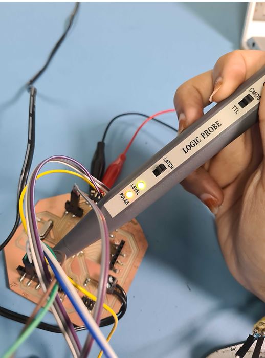
(Link)In this week group assignment, I’m measuring & testing the input digital circuits using Logic Probe measurements tool.
The logic probe one of the low-cost tools that easy to use help in testing the digital circuits with very basic information.
So if the green light appear it mean that that the logic high which state that it is able to detect digital pulses as shown when I tested the digital flow in my board.
Individual assignment
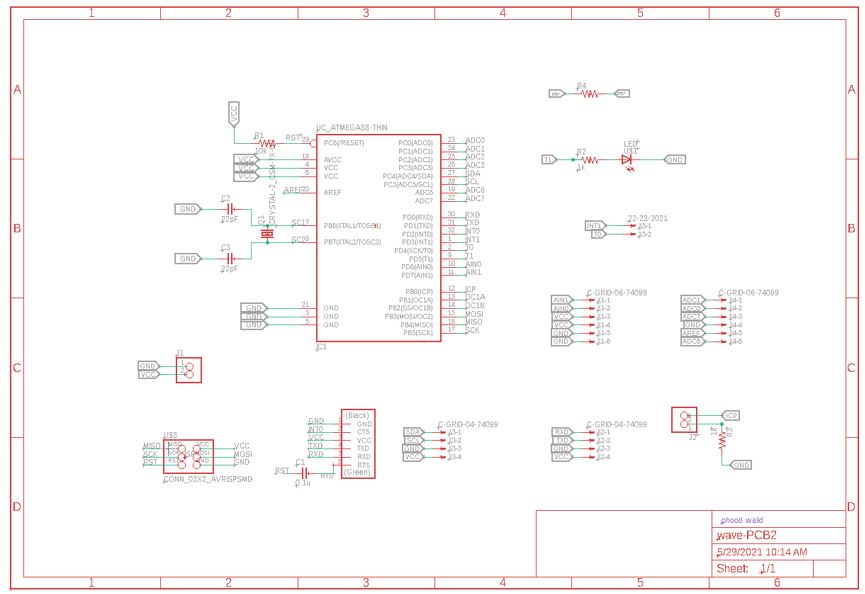
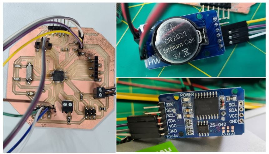
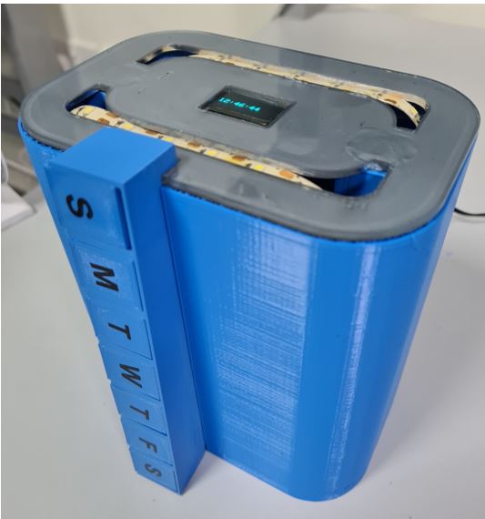
This week I will be designing PCB with ATMEGA328P as microcontroller using Eagle CAD software, then I will add an Input.
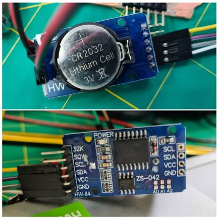
Using RTC module that give real time reading to add the Time as input for my final project. Because it is important to run my project with a real time and keep it up even if the system shutdown since it give indication of the time to take the medicine.
from our learning path of Week6 Electronics Design I design my board for my final project.
My Schematic design
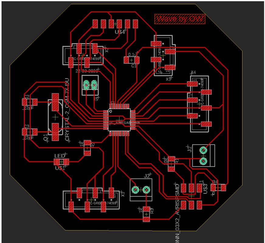
My Board Design
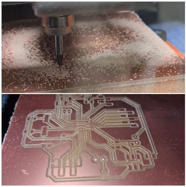
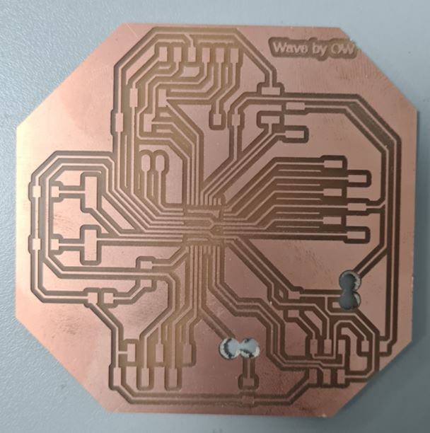
Electronic Production:
Roland SRM-20 was used to mill the PCB board
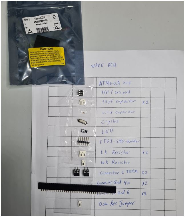
List of the components used in my board:
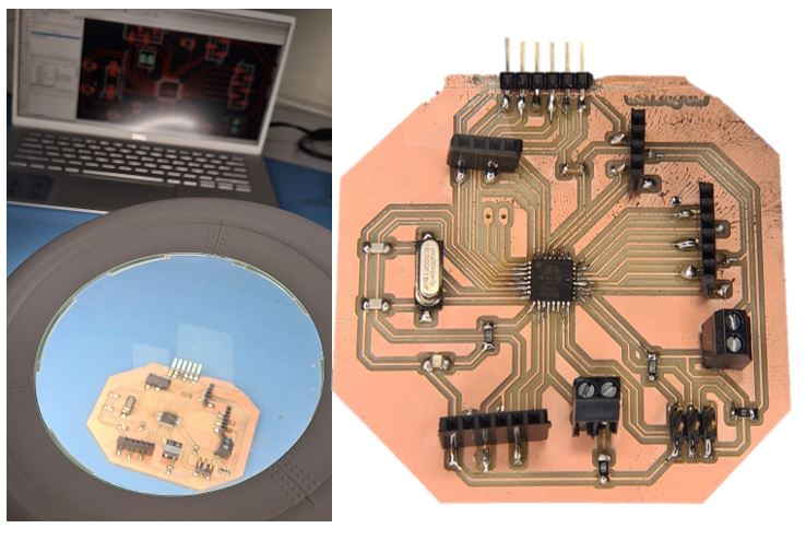
soldering the components in the correct orientation as shown in the Board Design
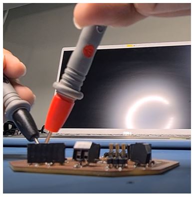
Next Component Connection Test, using multimeters to check the connectivity of PCB
Programming my PCB using Arduino software
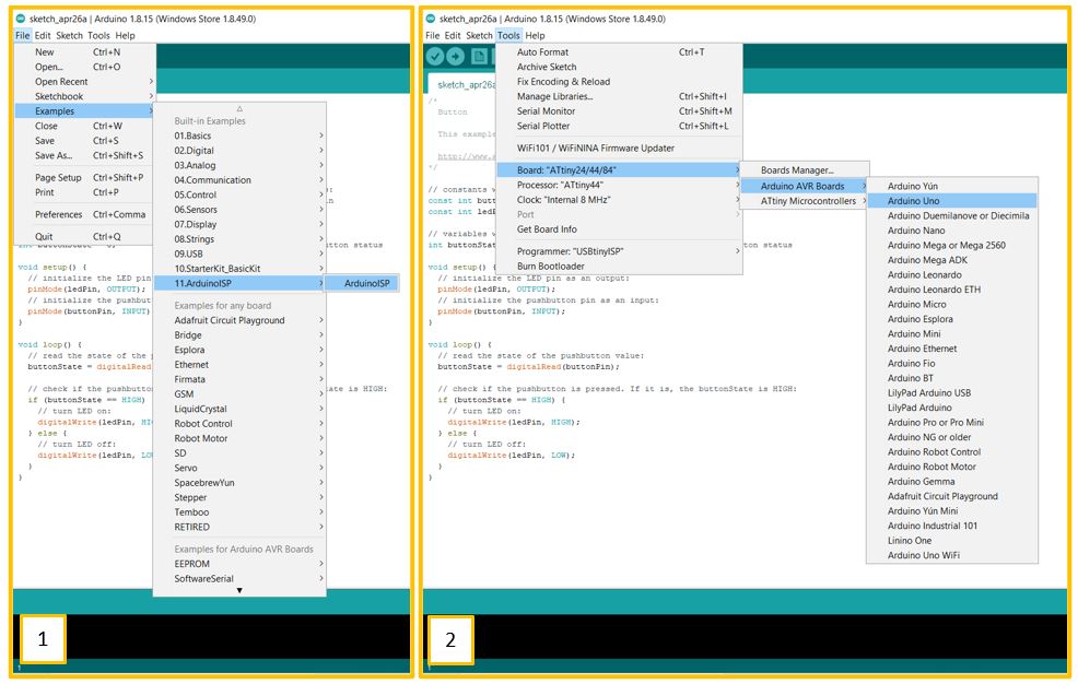
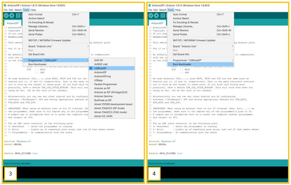
to program ATMEGA328P I need to burn the Bootloader to the ATMEGA328P. by following the steps in this link.
Then connecting my PCB with RTC module with screen
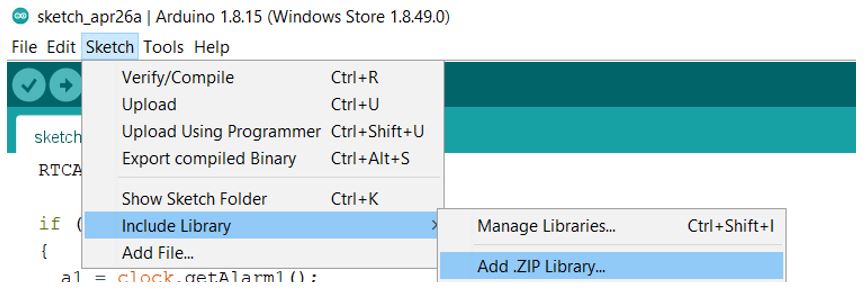
Download the needed library from this link.
Then add the library.
Then programming the RTC following the steps from this link. I will be explaining the code.
First, I need to mention the libraries I added in the code as following
#include <DS3231.h>  //RTC library
#include <Wire.h> //I2C communication
#include <Adafruit_GFX.h>  //LCD
#include <Adafruit_SSD1306.h> //LCD library
Then add the code for the LCD that display the real time
#include <Adafruit_SSD1306.h> //LCD library
#define SCREEN_WIDTH 128 // OLED display width, in pixels
#define SCREEN_HEIGHT 64 // OLED display height, in pixels
Then specified the variable that I will use in the code and for an SSD1306 display connected to I2C
Adafruit_SSD1306 display(SCREEN_WIDTH, SCREEN_HEIGHT, &Wire, -1);
DS3231  rtc(SDA, SCL);
Time  t;
#define buz 6
#define Led 7
int Hor;
int Min;
int Sec;
Then I set the date & time for the RTC, also this setting will be written once because the RTC has a battery which will keep the real time even if it is not powered
void setup()

{
  Wire.begin();
  rtc.begin();

  // The following lines can be uncommented to set the date and time

  //rtc.setDOW(TUESDAY);     // Set Day-of-Week

 // rtc.setTime(19, 26, 0);     // Set the time to 12:00:00 (24hr format)

  //rtc.setDate(6, 15, 2021);   // Set the date

  //delay(2000);

}
Then in the loop I write the code to get the time from RTC and save it in the variable so I can use it when I set the alarm time.
void loop()
{
  t = rtc.getTime();
  Hor = t.hour;
  Min = t.min;
  Sec = t.sec;
To preview the time on the LCD screen I added this code
  display.clearDisplay();
display.setTextSize(2.5);
display.setTextColor(WHITE);
display.setCursor(0, 30);
// Display static text
display.print(Hor);
display.print(":");
display.print(Min);
display.print(":");
display.println(Sec);
display.display();

//display.clearDisplay();
//display.setTextSize(1);
//display.setTextColor(WHITE);
//display.setCursor(0, 10);
//// Display static text
//display.println(t);
//display.display();
digitalWrite(6, HIGH);
digitalWrite(7, HIGH);
Then I added this code to compare the current time with the alarm
if( Hor == 19 && Min == 39) //Comparing the current time with the Alarm time
Combining all codes as following
#include <DS3231.h>

#include <Wire.h>

#include <Adafruit_GFX.h>
#include <Adafruit_SSD1306.h>

#define SCREEN_WIDTH 128 // OLED display width, in pixels
#define SCREEN_HEIGHT 64 // OLED display height, in pixels

// Declaration for an SSD1306 display connected to I2C (SDA, SCL pins)
Adafruit_SSD1306 display(SCREEN_WIDTH, SCREEN_HEIGHT, &Wire, -1);


DS3231  rtc(SDA, SCL);

Time  t;

#define buz 6
#define Led 7

int Hor;

int Min;

int Sec;

void setup()

{
if(!display.begin(SSD1306_SWITCHCAPVCC, 0x3C)) { // Address 0x3D for 128x64
    Serial.println(F("SSD1306 allocation failed"));
    for(;;);
}
  Wire.begin();

  rtc.begin();


  pinMode(6, OUTPUT);  //Buz

  pinMode(7, OUTPUT);  //Led


  // The following lines can be uncommented to set the date and time

  //rtc.setDOW(TUESDAY);     // Set Day-of-Week to SUNDAY

 // rtc.setTime(19, 26, 0);     // Set the time to 12:00:00 (24hr format)

  //rtc.setDate(6, 15, 2021);   // Set the date to January 1st, 2014

  //delay(2000);

}


void loop()

{


  t = rtc.getTime();

  Hor = t.hour;

  Min = t.min;

  Sec = t.sec;

display.clearDisplay();
display.setTextSize(2.5);
display.setTextColor(WHITE);
display.setCursor(0, 30);
// Display static text
display.print(Hor);
display.print(":");
display.print(Min);
display.print(":");
display.println(Sec);
display.display();

//display.clearDisplay();
//display.setTextSize(1);
//display.setTextColor(WHITE);
//display.setCursor(0, 10);
//// Display static text
//display.println(t);
//display.display();

digitalWrite(6, HIGH);
digitalWrite(7, HIGH);

 if( Hor == 19 &&  Min == 39) //Comparing the current time with the Alarm time

{

Buzzer();

Buzzer();

light();

light();

display.clearDisplay();
display.setTextSize(1.5);
display.setTextColor(WHITE);
display.setCursor(0, 25);
//// Display static text
display.println("Hi, Take Med!");
display.display();

Buzzer();

Buzzer();

light();

light();

}

 delay(1000);

}


void Buzzer()

{

digitalWrite(6,HIGH);  // turn the buzzer on

delay(500);

digitalWrite(6, LOW);  // turn the buzzer off

delay(500);

}

void light()

{

digitalWrite(7,HIGH);    // turn the LED on

delay(500);

digitalWrite(7, LOW);   // turn the LED off

delay(500);

}
then the real time showed on the screen
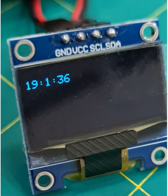
I used this input & the code in my final project.
Challenges & Important Tips:
I faced 3 main challenges I will discuss it below & will list some tips that I used to overcome it:
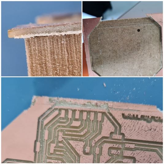
1- I used fab modules to convert the files to (.rml) for milling but unfortunately fab modules not supporting PCB with holes the result as shown below in the picture. therefore, our instructor Eng.Hashim teaches me different method by using Flatcam to generate CNC files.
Step by step how to Generate CNC files from Eagle PCB board using Flatcam:
2- the copper plate wasn’t fixed properly, therefor the end of the board wasn’t milled properly as you can see in the below picture. I didn’t want to waste more material specially this is my second board after the failure of the first one. So I cut the end line manually with cutter.
3- I didn’t design extra pins in my PCB for (SCL & SDA) to connect the RTC & the screen because bot need the same pins, so I link the screen with the pins in the RTC module as shown below.