I decided to make a 3D food printing machine because I love food and I also I love the Quality in Services.
It will help the best organizations in the world to achive the world growth and development.
The 3D food printing technique is to make things better and it is useful in manufacturing food products with customisation in shape, colour, flavour, texture, and nutrition.
It can give the people individual needs and preferences.
Goal:
Plan and sketch a potential final project.
Learning outcomes:
Communicate an initial project proposal.
This week is all about Design & build the machine!
Plan
The project will consist of three main parts:
Mechanical Design
Electronics Design
Software Design
Mechanical Components:
Aluminum profiles 20x20mm 600mm long (X2)
Aluminum profiles 20x20mm 300mm long (X5)
12mm rod 310mm (X2)
12mm rod 530mm (X2)
12mm rod 140mm (X2)
Lead screw 500mm (X2)
Lead screw 280mm (X1)
Lead screw 120mm (X1)
12mm linear bearing (X12)
608zz bearing (X4)
T nut M5 (X36)
M6 x 25mm screws (X4)
M5 x 10mm screws (X34)
M5 x 16mm screws (X10)
M3 x 20mm screws (X8)
M3 x 12mm screws (X38)
Electronics Components:
Stepper motors (X4)
Stepper drivers (X4)
ATMega (X1)
Power supply (X1)
DC connector (X1)
Jumpers (X14)
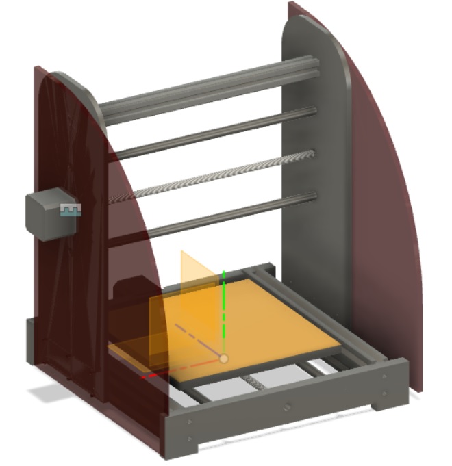
3D Design of Food Printing Machine:
Design
Mechanical Design
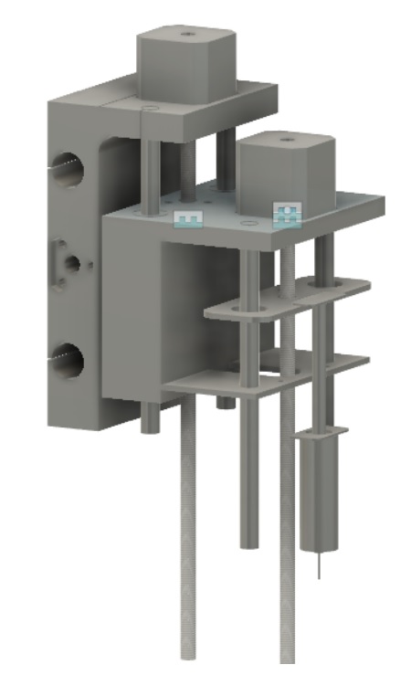
z-axis design:
There are four main parts: mechanism of moving along the axis, mechanism of fixing the motor (injection) on the axis, Motor holder to press the injection and the motor that Press the injection
The design look like this:
The first try in design progress
My final desgin looks like that :
The design was made to hold the injection and press in it.
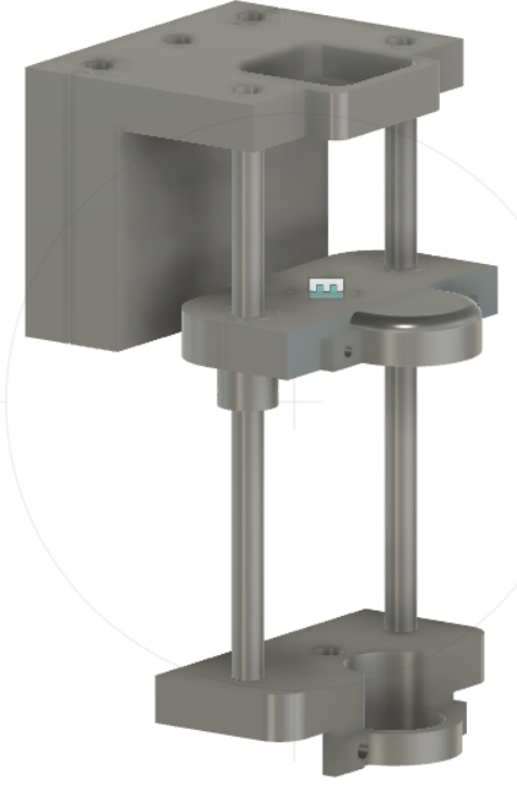
Y-Axis Design:
It is composed of two side pieces.
The two side pieces connected by NEMA17 stepper motor and two rods.
NEMA17 stepper motor is placed in the medial.
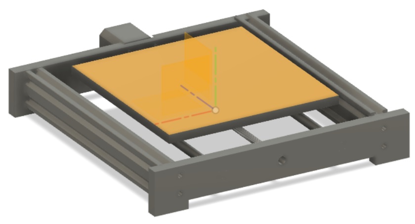
The design of Y-Axis design in Fusion360
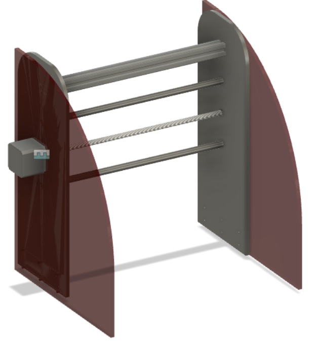
X-axis Design:
The parts of the design consist of two aluminum profiles.
Two side plastic pieces that fit at one end of each other.
The two plastic pieces connect with two metal rods and a NEMA17 stepper motor in the middle.
Fabrication
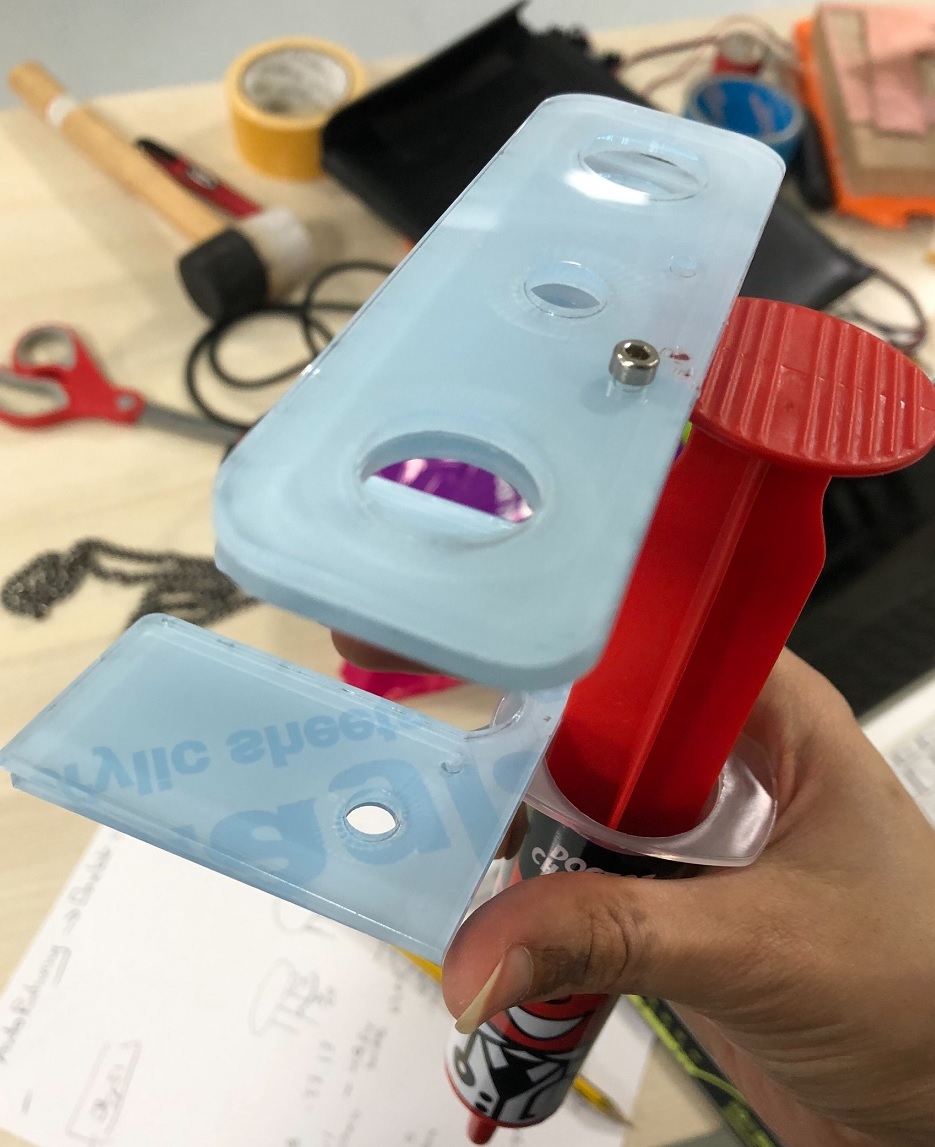
Fabrication of z-axis:
For the z-axis design there are four parts:
1.Injection holder.
2.Press the injection.
3.Motor holder to press the injection.
The main holder that moves the up and down.
First I start to design a simple design that is not that much professional and it was not staple I use the laser cut machine to cut the part of the design.
The design was done by useing an ultimaker printer with PLA.
The design for the z-axis injection holder and the press was perfect in design and sizes from the first time.
The motor holder to press the injection it takes 12 hours to be done. First time I go to check it was missing. The second time it is failed in printing (It failed due to the cold room temperature) so I try to printed again, it looked like this:
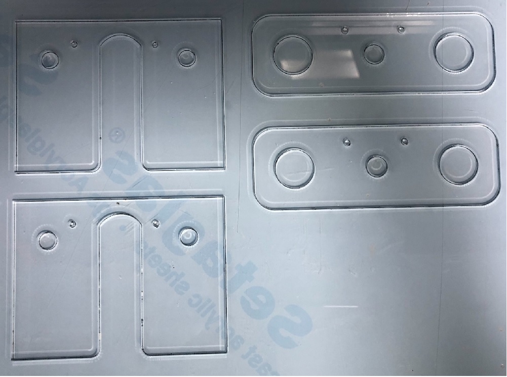
Fabrication of Y-Axis:
For the side pieces the white HDPE plastic is used for cutting by using the ShopBot machine.
I decide to use the one that we have been used in the previous group assignment that we design it in the mechanical design week.
But I decide to change it because the injection was long so it will take a more space.
The screws holes are 3mm by using drilling bit 3mm.
For cutting the outline used a 6mm drilling bit.
Fabrication of X-Axis:
The 3D printed the linear rail shaft supports was ready from the previous group machine design.
For the bed sheet I used 3mm MDF sheet with Universal Laser PLS6MW Laser, settings the power= 100%, speed=2.6%, PPI=300 and also white acrylic the setting .
Because the chocolate can be mild I use a fan to make it hard.
Wiring Box:
I make an electronic box for the electronics compact.
I attached the box in the Y-axis middle of the aluminium profiles behind the machine.
The box is useful because it hides also this mess.
Assembly
Mechanical Assembly
I decide to open the machine that has been made by the group to rebuild it again.
Because the idea of fablab is to not west material.
As it is shown in the video below :
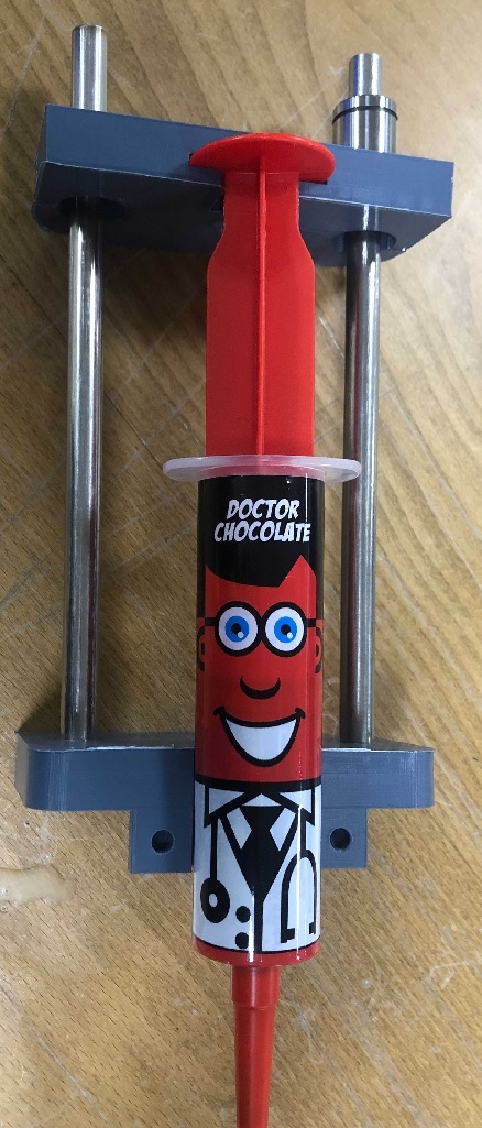
assembly of z-axis:
For the linear rail I will add the ball bearing to the holes the sizes were fit.
Then I added the anti back-lash nut then I screw it.
There are two motors are in the z-axis one to move it right and lift and the other one to press in the injection.
Then I added the injection and tightened it.
The final result was like this:
Electronics Design
List of electronics components used:
NEMA17 Stepper Motors (X3)
stepper motor driver(X3)
Controller Board ATmega(X1)
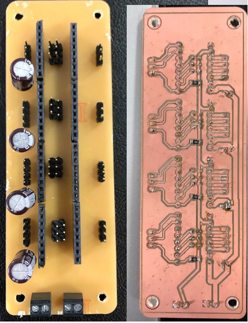
Stepper motoe Board(X1)
Power Supply (X1)
My project consists of four stepper motors.
One motor is used for the movement of X-Axis, one for the Y-Axis and tow for the Z-Axis.
Each motor is driven by one stepper motor driver Separately.
Drivers are connected to the controller board that I was made.
The motors will be powered with a 12V (generated by the power supply).
The connecting wires were made longer to make the movement in the y-axis easier.
The board was placed on the fixed aluminium profile (back side).
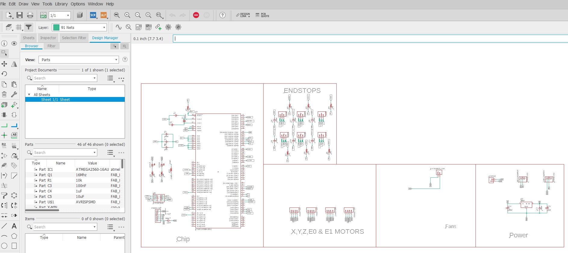
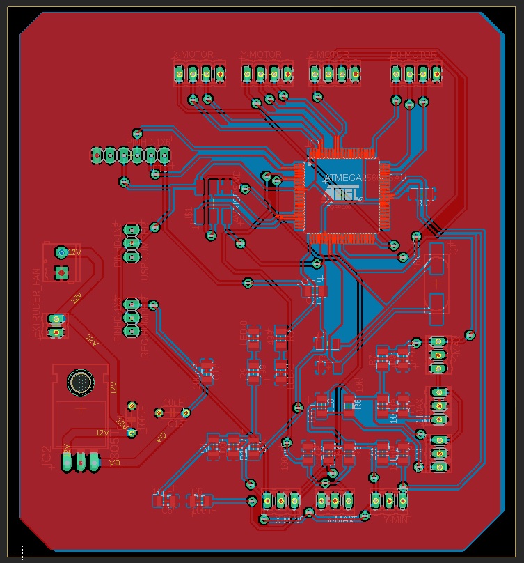
I start to design my first double-sided board for the project.
Usually for PCB milling I use CNC machine in fab lab.
I use the FlatCAM to generate the g-code.
FlatCAM is free software that converts Gerber to a single G-code file that integrates the paths and drill files, than we can use the Milling Machine Software.
For this kind of machine, we command & using the machine software.
Results:
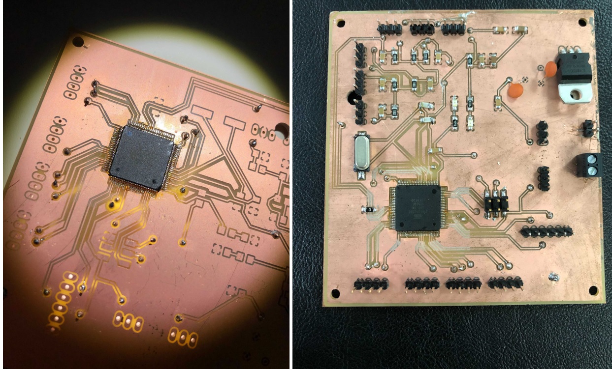
Assembling:
The processor was difficult because of the numbers of components to be solder.
The board was double-sided, so it was difficult to deal with it was first time experience.
It was difficult to take it out and it is almost damage.
The processor of soldering should be starting from the vias to the rest.
The Atmega 2560 clearance and distance is less than 0.4 or 1/64 inch so we need to use milling bit with 0,15mm and the rest of milling traces the normal 0.4mm milling bit.
The first step is to export the file to flatCAM file>>cam processer>> process job>>select place>>ok
Flat CAM
Setting
Open flatCAM>>edit>>unite>>mm
We will put the same speed that we are using in fab modules.