11. Input devices
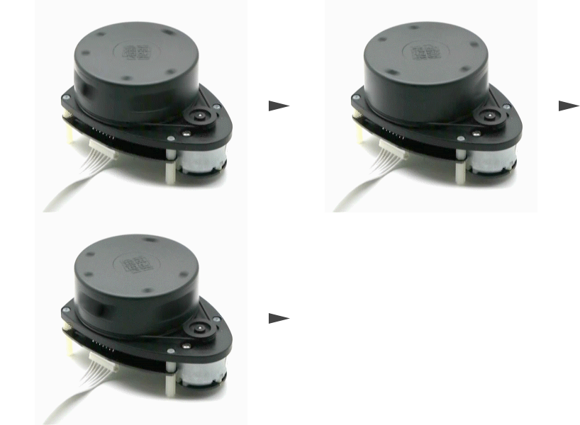
This week I worked on in reading data from RPLIDAR A1M8-R6 - 360 Degree Laser Scanner


In the following video the LED will LED blink faster when the obstacle get closer to the sensor.
Wiring
- First I need to wire the RPLidar with my design board which I have made in Electronics Design Week
| My Board Pin | RPLidar |
|---|---|
| FTDI GND | GND |
| FTDI RX | RX |
| FTDI TX | TX |
| VCC | V5.0 |
| GND | GND |
| FTDI CTS | MOTOCTL |
| VCC | VMOTO |

- For programing I wire Arduino UNO board with ISP header of my board
| Arduino UNO Pin # | New Board ISP Port |
|---|---|
| 12 | 1-MISO |
| 5V | 2-VCC |
| 13 | 3-SCK |
| 11 | 4-MOSI |
| 10 | 5-RST |
| GND | 6-GND |

- Here is the full wiring

RPLIDAR library
-
First you’ll need to install the RPLIDAR library from GitHub by download the ZIP file

-
Export RPLidarDriver folder to Arduino libraries folder

Arduino Code
-
Open Arduino IDE and go to File >> Examples >> RPLidarDriver >> simple_connect

-
I modify the code by adding the following code
      //perform data processing here...

    if (angle >= 0.0 && angle <= 1.0) {
      if ( distance <= 150 && distance > 100)
        interval = 500;
      else if ( distance <= 100 && distance > 50)
        interval = 100;
      else if ( distance <= 50 && distance >= 0)
        interval = 0;
      else
        interval = 2000;

      timeNow = millis();
      if ( (timeNow - timeOld) >= interval) {
        timeOld = timeNow;
        if (LEDStatus == LOW)
          LEDStatus = HIGH;
        else
          LEDStatus = LOW;
      }
      digitalWrite(pinLED, LEDStatus);
    }
- Here is the full code
// This sketch code is based on the RPLIDAR driver library provided by RoboPeak
#include <RPLidar.h>

// You need to create an driver instance
RPLidar lidar;

#define RPLIDAR_MOTOR 2 // The PWM pin for control the speed of RPLIDAR's motor.
// This pin should connected with the RPLIDAR's MOTOCTRL signal


float distanceOld = 0;
unsigned long timeNow = millis();
unsigned long timeOld = millis();
unsigned long interval = 0;
int pinLED = 3;
byte LEDStatus = LOW;

void setup() {
  // bind the RPLIDAR driver to the arduino hardware serial
  lidar.begin(Serial);

  // set pin modes
  pinMode(RPLIDAR_MOTOR, OUTPUT);
  pinMode(pinLED, OUTPUT); // initialize digital pin as an output.
  digitalWrite(pinLED, HIGH);
}

void loop() {
  if (IS_OK(lidar.waitPoint())) {
    float distance = lidar.getCurrentPoint().distance; //distance value in mm unit
    float angle    = lidar.getCurrentPoint().angle; //anglue value in degree
    bool  startBit = lidar.getCurrentPoint().startBit; //whether this point is belong to a new scan
    byte  quality  = lidar.getCurrentPoint().quality; //quality of the current measurement

    //perform data processing here...

    if (angle >= 0.0 && angle <= 1.0) {
      if ( distance <= 150 && distance > 100)
        interval = 500;
      else if ( distance <= 100 && distance > 50)
        interval = 100;
      else if ( distance <= 50 && distance >= 0)
        interval = 0;
      else
        interval = 2000;

      timeNow = millis();
      if ( (timeNow - timeOld) >= interval) {
        timeOld = timeNow;
        if (LEDStatus == LOW)
          LEDStatus = HIGH;
        else
          LEDStatus = LOW;
      }
      digitalWrite(pinLED, LEDStatus);
    }
  } else {
    analogWrite(RPLIDAR_MOTOR, 0); //stop the rplidar motor

    // try to detect RPLIDAR...
    rplidar_response_device_info_t info;
    if (IS_OK(lidar.getDeviceInfo(info, 100))) {
      // detected...
      lidar.startScan();

      // start motor rotating at max allowed speed
      analogWrite(RPLIDAR_MOTOR, 255);
      delay(1000);
    }
  }
}
Testing
In the following video the LED will LED blink faster when the obstacle get closer to the sensor.
ROS
Useful links
Last update: June 16, 2021