week5
This week’s task: make an in-circuit programmer by milling and stuffing the PCB, test it, then optionally try other PCB processes
PCB fabrication requirements
- components
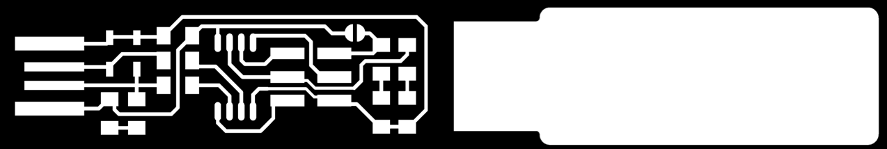
- Designing the schematic and board
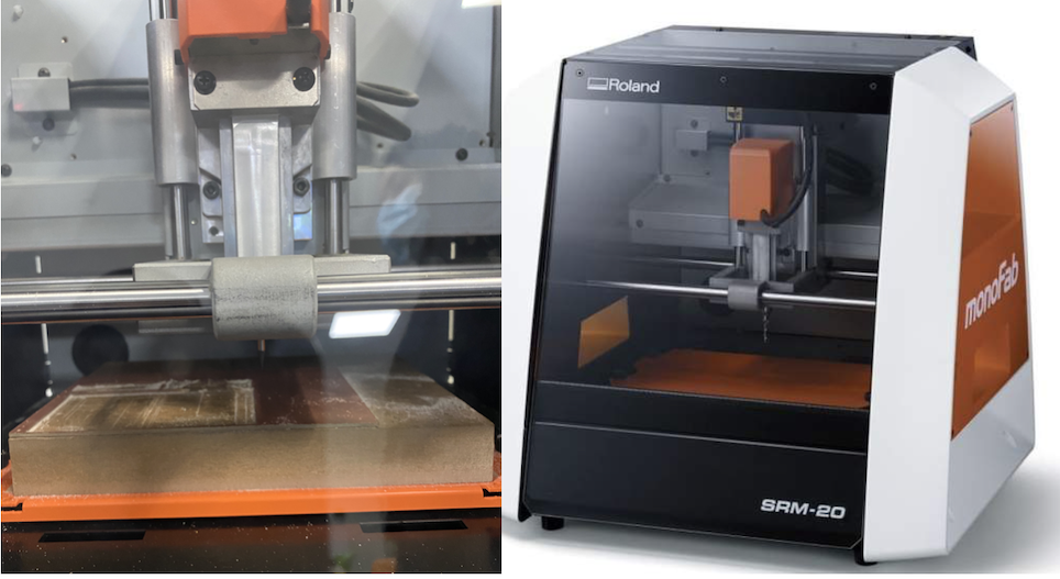
- milling
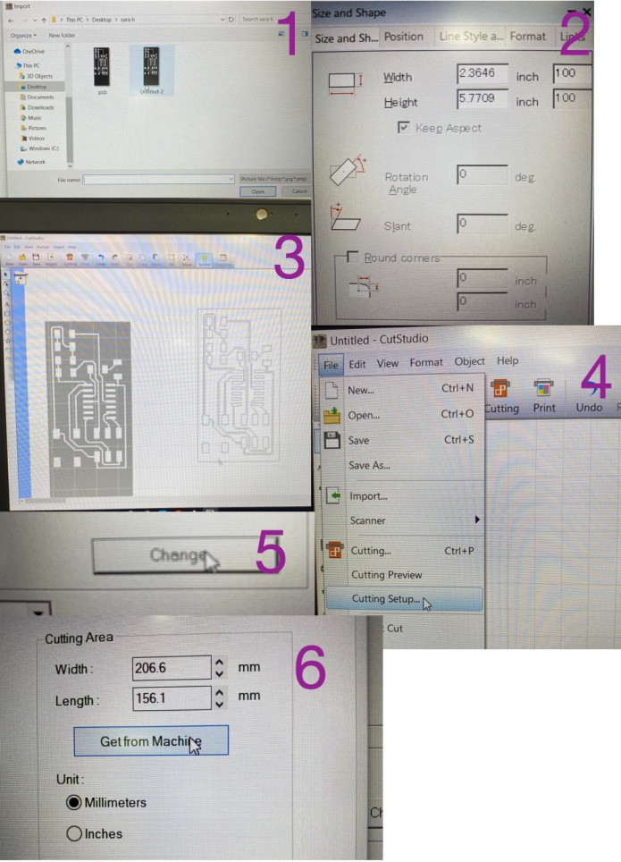
- Downloaded the traces and outline from fabacademy website
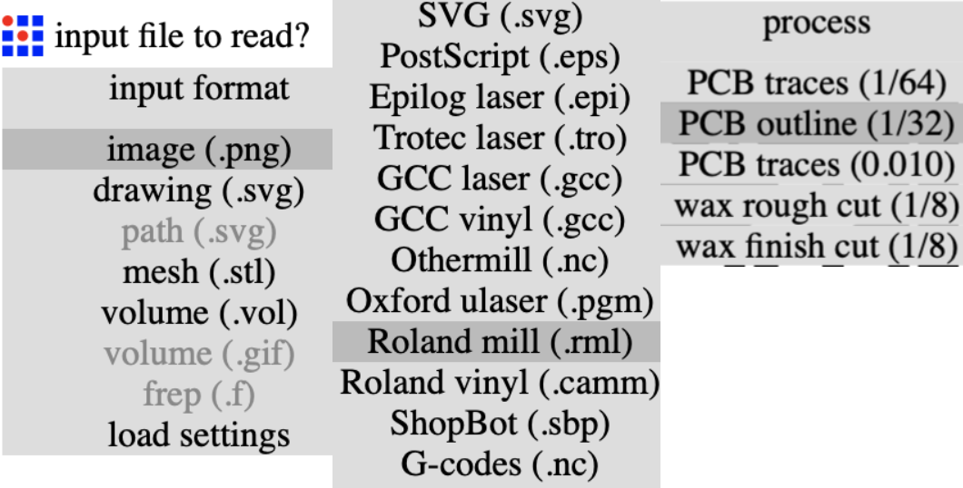
- Open fab modules and edit the setting for both traces and outline
- Then click on Roland mill because it is the provided machine in our Fablab
- I changed some setting according to what our instructor gave us, and kept the rest as it was in default
- click on save then save as rml
- i inserted my usb to the laptop connected to the milling machine
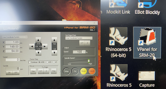
- click on the Vpanel for SRM20 icon to launch the software
- edit the setting and move the arrows xy and z for accurate placement
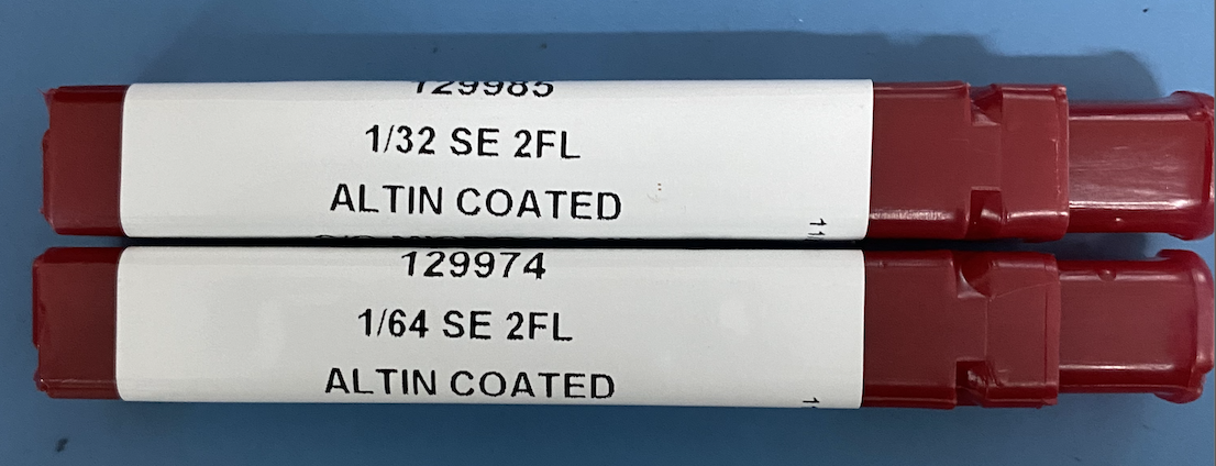
- i chose the shorted needle 1/32 for the outline and longer needle 1/64 for the traces
- i started with the design because i dont want the plate to move and ruin placement
- to prepare the surface, first i took the metal place and taped it with strong adhesive to a square mdf board
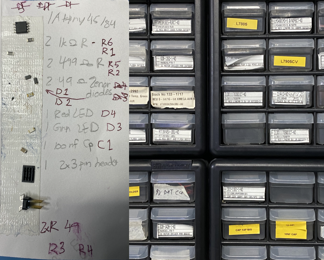
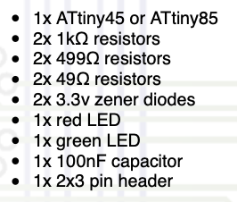
- collect all the components together
- these are the components i used and i got the list from fabacademy website page
- first use an iron to heat pcb's pad
- while it heated, add abit of solder
- hold the components with a tweezer because the pad and the iron is hot and can get dangerous
- add solder to the top of each components but make sure you dint overlap the areas because it could cause a short circuit
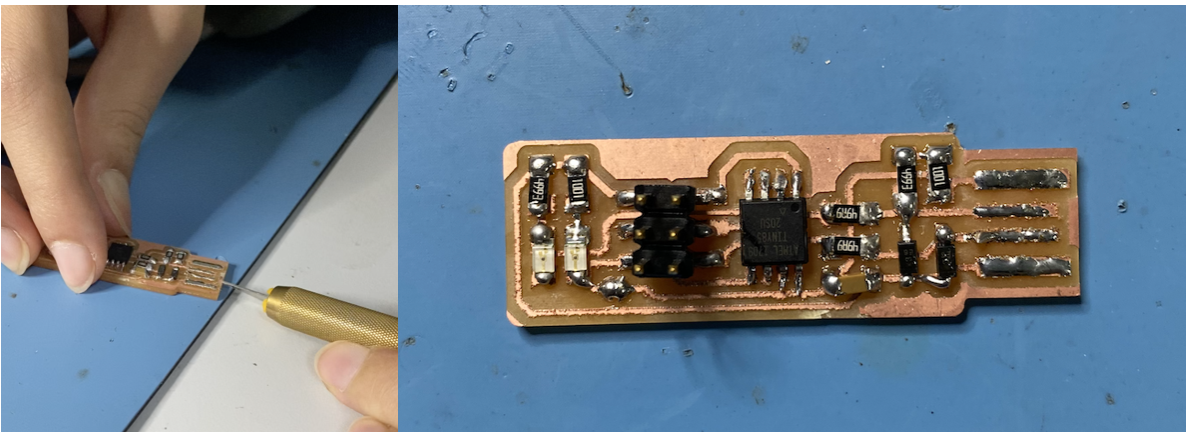
- remove this part of the pcb
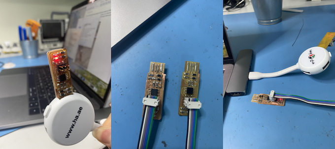
- this is the final look of the PCB
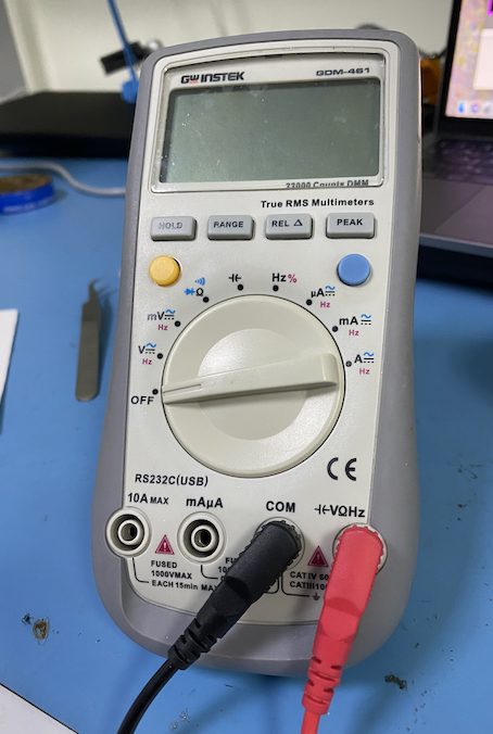
- before starting to program,check for any short circuit by using a multimeter
- for this step i followed fatma's programming page
- i started by downloading homebrew to downlaoad the other softwares i needed
- lastly restart terminal, then check if the programs are installed correctly
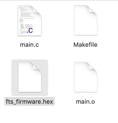
- next i opened firmware folder after downloading it
- then type "make" in the terminal to get the hex file
- get in desktop > fts_firmware_bdm_v1
- check if the fabisp is connected by clicking on about this mac > system report > usb
- if the isp showed in the usb tap it means it was successfully connected
- the isp's light is working and the laptop recognised it
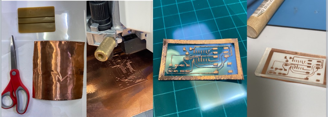
- i printed using sara's design
- i cut out the design and removed the exrra carefully using an xacto knife and a tweezer
- then i sticked the pcb to a transfer sheet
- then cut out a piece of acrlyic using the lasercut machine and placed it underneath the pcb
Steps I followed to make the pcb
for engraving:
for soldering:
programming:
brew tap osx-cross/avr
brew install binutils
brew install gcc
brew tap osx-cross/avr && brew install avr-gcc
brew install avrdude
avr-gcc --version
make -v
open terminal
make flash
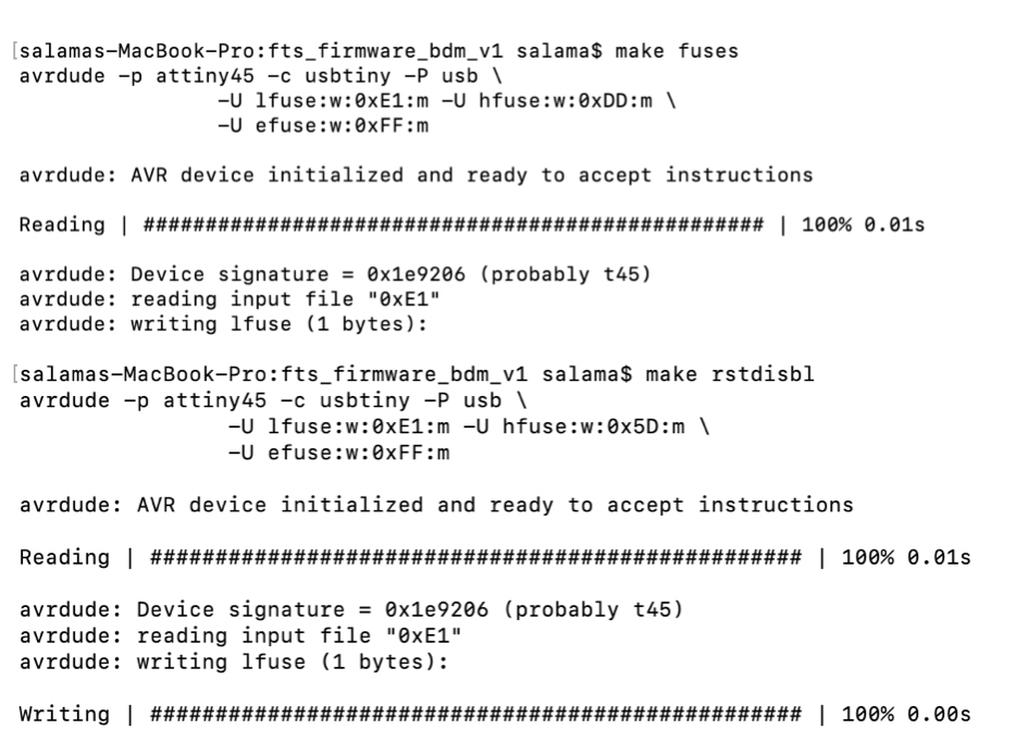
make fuses
make rstdisbl
group task:
i made a flexible pcb using vinyl cutter machine
steps: