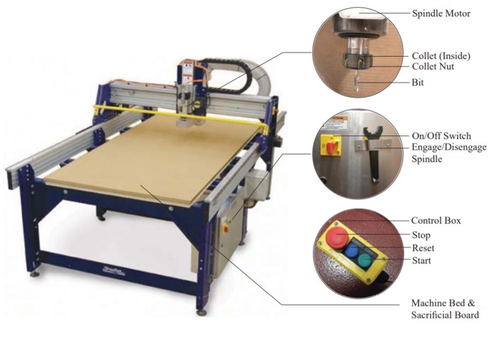
Computer Controlled Machining

Group  Assignment

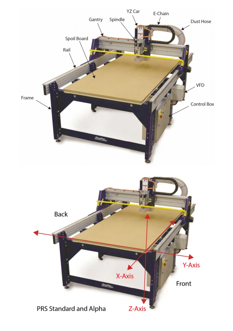
To test runout, alignment, speeds, feeds, and toolpaths for our CNC machine.

GET STARTED

CNC

Fullspectrum Laser Cutter

What is CNC?

Numerical control is the automated control of machining tools and 3D printers by means of a computer. A CNC machine processes a piece of material to meet specifications by following a coded programmed instruction and without a manual operator.

What materials can I use?

MDF, plywood, solid wood, foam, and plastics.

Which machine will we use?

We will use ShopBot PRSalpha 120-60 CNC machine, from ShopBot, an American CNC machine. Easy to configure and reconfigure, learn, and use, the PRSalpha CNC delivers affordable, full-production performance in digital fabrication of wood, plastic, aluminum, and other materials.

What are the main parts of the PRSalpha 120-60 CNC machine?

← ← ← ←

What can we fabricate with a PRSalpha 120-60 CNC machine?

There are many applications that can be done by this machine. You can make furniture, cabinets, dollhouses, real houses! As we did in Fablab Dhahran team the Fab House, Sign making, so you can execute all kinds of ideas including creating components in 3D.


Saftey and Tools

Safety while using ShopBot PRSalpha

- Always wear safety glasses and hearing protection when operating CNC machines.

- Always wear safety glasses when closely observing cutting tools. Always wear safety boots or other suitable footwear.

- Always keep long hair covered when operating CNC machines.


Stopping ShopBot PRSalpha in an Emergency

Laser seetings
 

What are the cutting tools used with ShopBot PRSalpha?

Cutting tools have two parts, the shank and flute. The shank is the section that goes into the tool holder. It must always be the same diameter as the holder. The flutes are the cutting edges of the bit. It may (or may not) be the same diameter as the shank.

Laser seetings

End mills router bits

Laser seetings

These bits are designed to cut while moving sideways through the material. There are two common styles of end mills, regular and ball end.

A regular end mill

has a flat end and is used for cutting at surfaces.

A ball end mill

has a hemispherical end and is used for 3D machining and finishing passes. Drill bits these are the same bits used in a hand drill or drill press. They are only for drilling holes, and only work when moving straight down.

Laser seetings

For more about bits

Laser seetings
 
Laser seetings

Upcut = clean bottom of the workpiece.

Downcut = clean the face of the workpiece.


60° V, 90°V, 120° V Flute

Laser seetings

For V-Grooving or Beveling Edges for Wood. The tools designed for V grooving or beveling edges of parts, and to cut a wide variety of wood products to produce a clean edge.


Testing the CNC Machine

We have created a series of test tasks in which engraving, cutting, curves, drilling using our CNC machine. With the same test we will test the press fit.


What will we do?

1. Insert the material to the CNC we will use MDF 15mm.

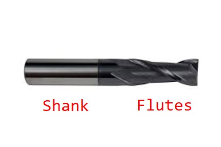
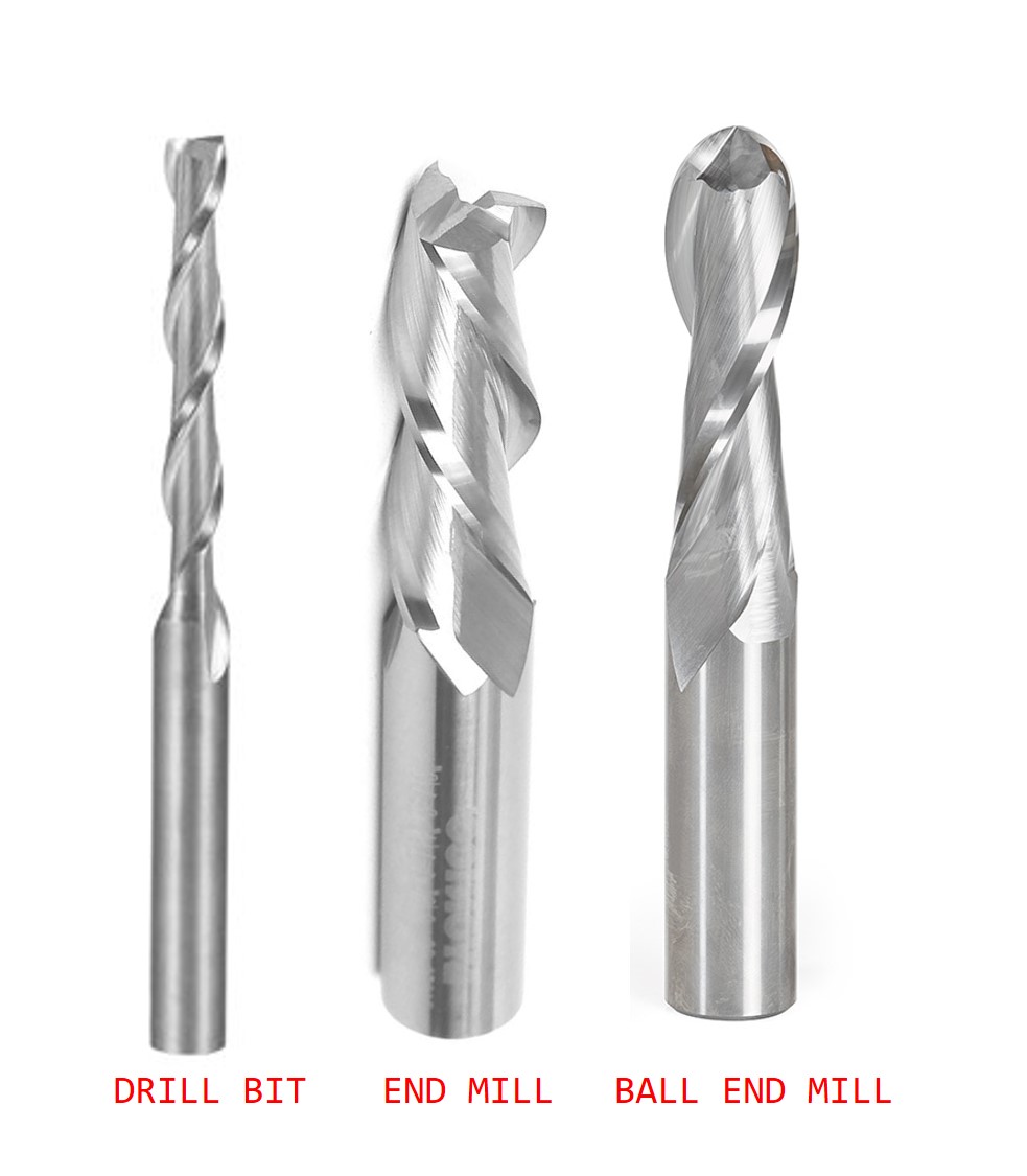
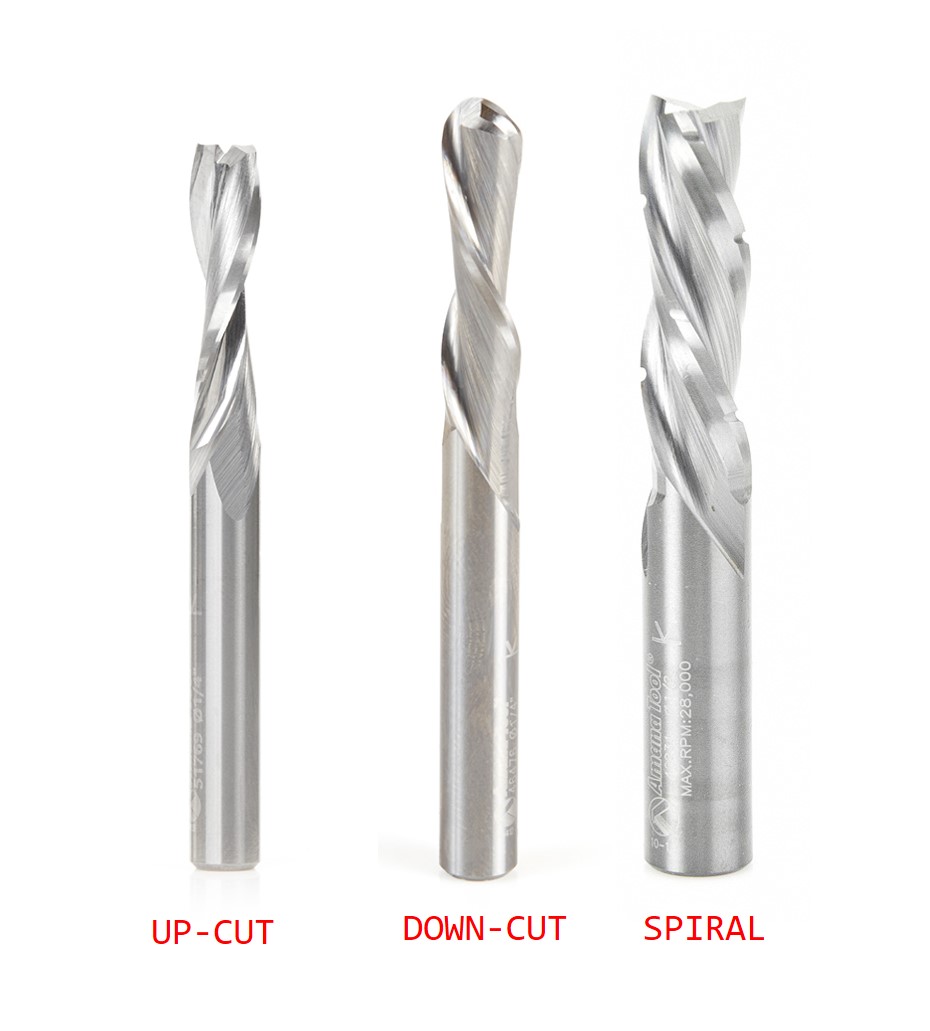
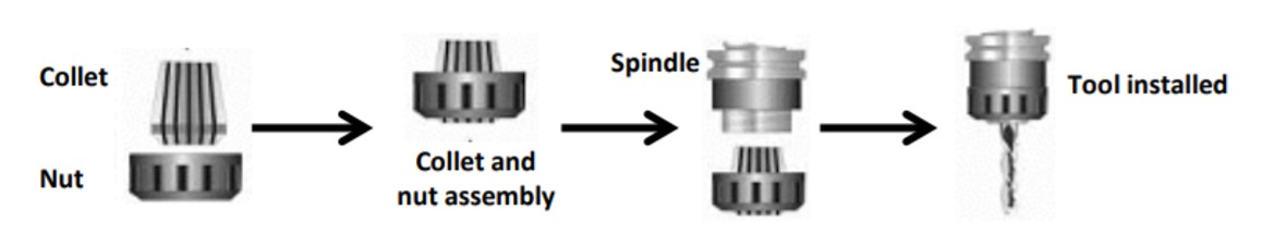
2. Changing the bit we will use 1/8 end mill bit for all the three processes.

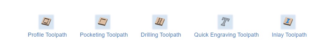
3. convert the toolpaths to Gcode file, by using VCarve pro software.

4. Demonstrate how to apply the design to the CNC machine and CNC software.

Laser seetings

This image will help you to know the parts we will be using in this stage.


Setup the material

First, we will Insert the material to the CNC. We will use MDF 15mm. For holding down material for cutting we will use screws as we already have a spoil board surfacing set up, you can screw the workpiece directly to the table.

Laser seetings

Changing the cutting bit

Laser seetings

  • Use the collet Wrenches and spanner tools to assemble the new bit. Turn the nut clockwise to loosen it and continue to loosen it by hand if necessary.
  • Changing bits Make sure the collet and nut are completely clean. If necessary, use a wire brush, compressed air, and/or mineral spirits to remove dust or excess grease. 
  • Spindles: Before inserting the bit, press the collet into the nut and listen for the “click.” If the collet does not seat, press it in at a slight angle. 
  • Once the nut is finger-tight, check the bit again to make sure that it has not slipped. Use the included wrenches to fully tighten the nut.

 
Laser seetings
 

VCarve pro software

Fullspectrum Laser Cutter   Fullspectrum Laser Cutter   Fullspectrum Laser Cutter   Fullspectrum Laser Cutter   Fullspectrum Laser Cutter   Fullspectrum Laser Cutter   Fullspectrum Laser Cutter   Fullspectrum Laser Cutter   Fullspectrum Laser Cutter   Fullspectrum Laser Cutter   Fullspectrum Laser Cutter   Fullspectrum Laser Cutter   Fullspectrum Laser Cutter   Fullspectrum Laser Cutter   Fullspectrum Laser Cutter


VCarve Pro gives you the power to produce complex 2D patterns with profile, pocket, drill and inlay toolpaths, plus gives you the ability to create designs with v-carving textures as well as import and machine unlimited Vectric 3D clipart or single model files.


From file > open > the design.


Set the job setup


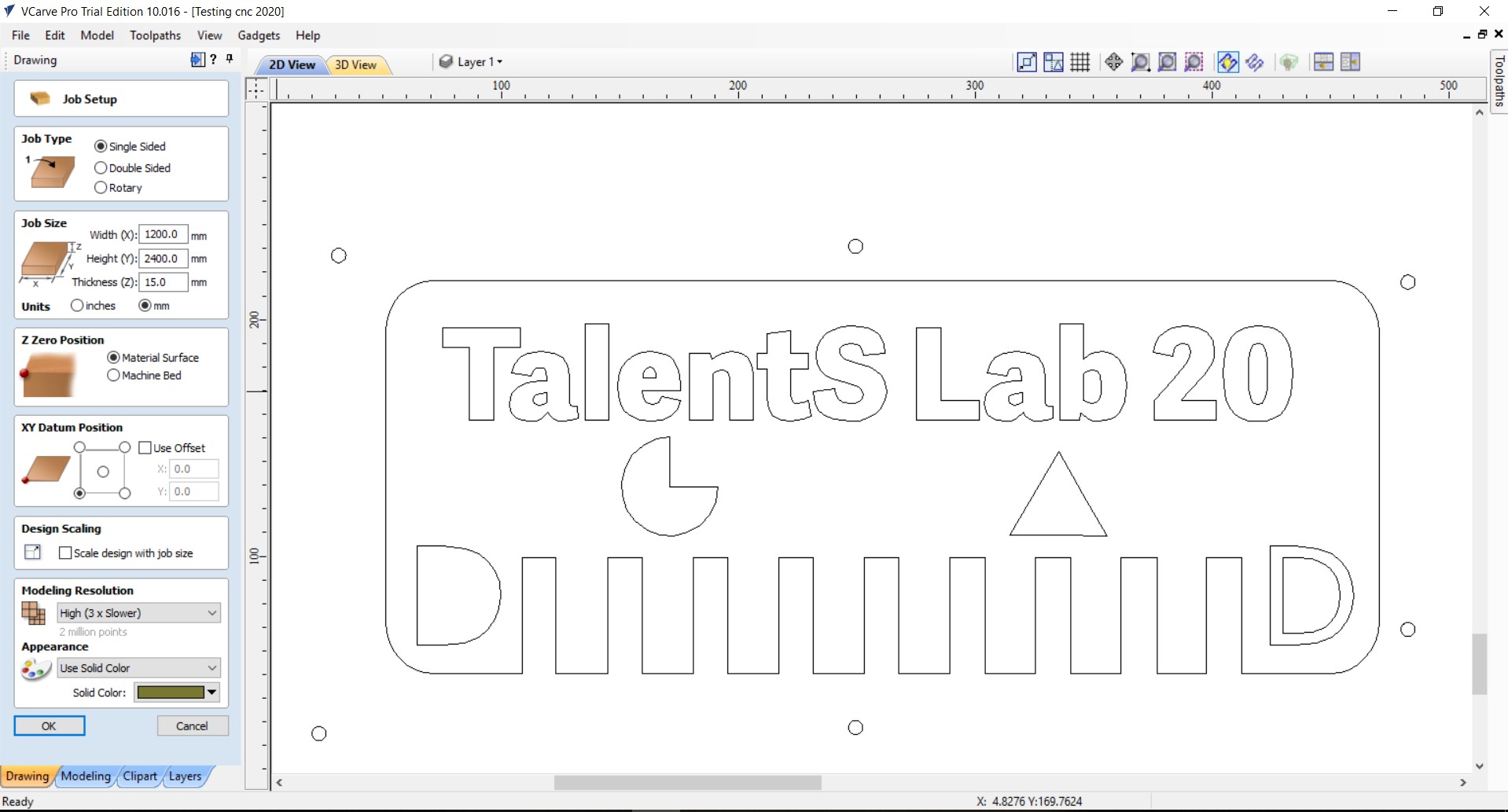
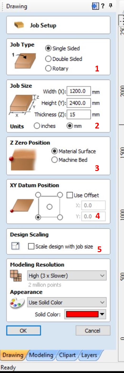
1.We chose the single sided as our job type.


2. The job size we added the workpieces size 1200x2400mm and it can be changed depending on your workpiece but always make sure the design can fit in the workpiece.


3. For Z zero position we chose the material surface.


4. We unchecked the use offset option and we prefer starting from the left corner.


5. Make sure to uncheck the design scaling.


6. Click Ok.


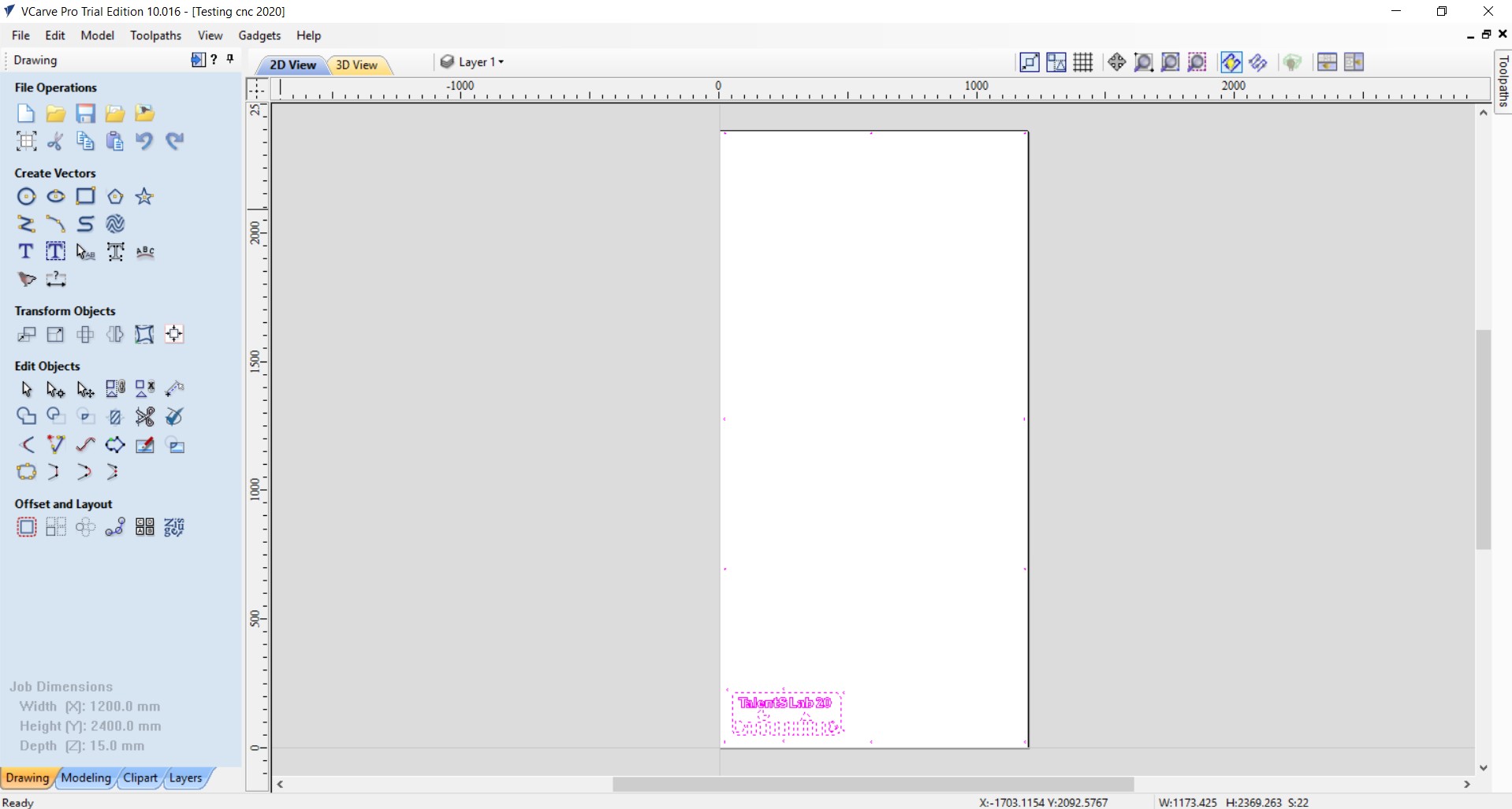
- Now after we set the job setup, we can see the design in 2D view or 3D view.

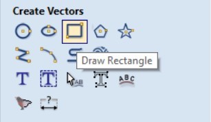
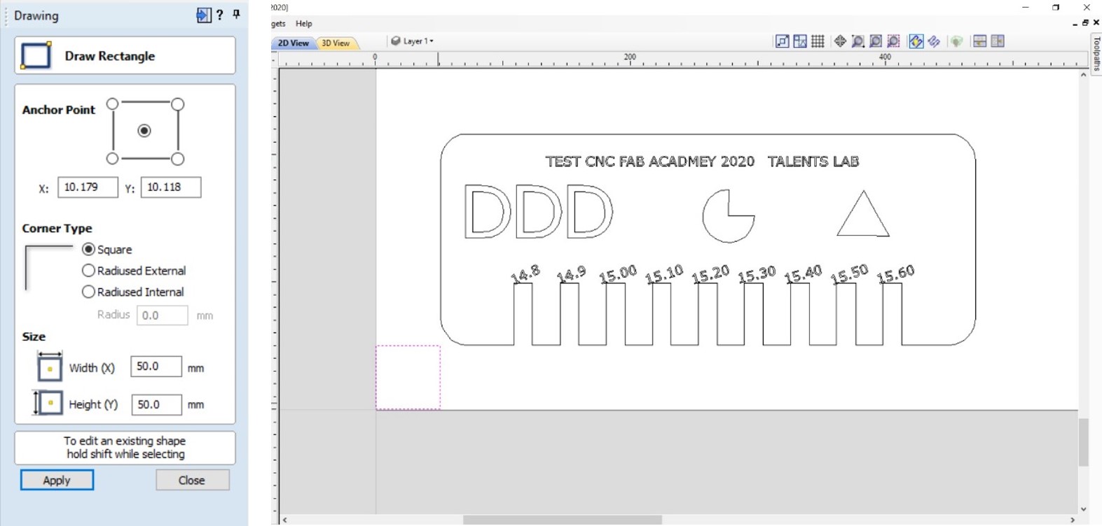
- The tools in the left side are very useful for quick design edits.

- And we used some of them to edit our design.


Set manual margins -recommended by the team-

We used the square shape to set 2cm from each side to avoid breaking the bit if it moved on the screws, while the machine started cutting.


Generate the toolpaths files

When we use the CNC we prefer to cut the inner parts first then the outer part, to make sure nothing will move during the cutting process so we will start generating the drilling then engraving part last the cutting part.In the VCarve program Profile toolpath means cutting, and the pocket toolpath means engraving.


Drilling Toolpath

We used the circle shape from the tools bar in the left to draw the rest of the screw holes.


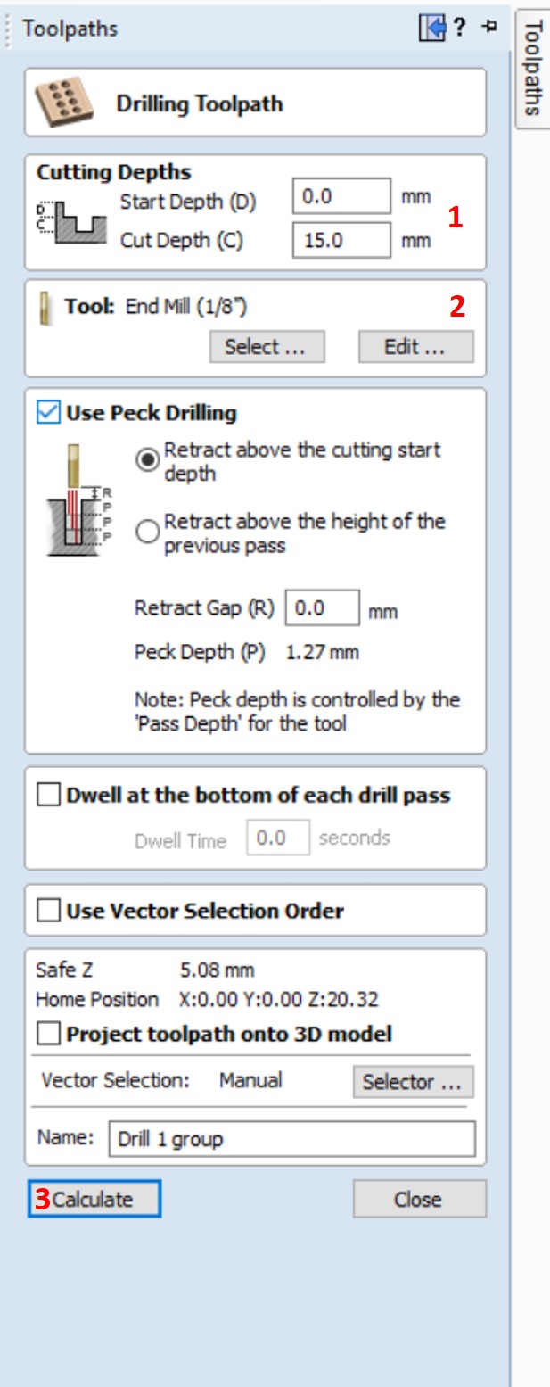
1.Add the same material thickness and you can add 5mm more to make sure it touches the spoil surface sheet. 

2.Choose the bit tool,  we chose 1/8 end mill.

3. Click on calculate to generate the toolpaths Gcode file.


The red line is the machine moving path.


Pocket toolpath


As you can see the text is too small to engrave with the bit we chose, how did we know that?

There is an error message popped up after we did all the steps.


So, we used Vcarve to edit the design by changing the text and delete the numbers because we do not have a smaller bit to do that.

After we edit, we will complete the pocket toolpath steps.


We selected the parts we want to engrave.


We clicked the pocket toolpath tool icon.


1.Set the cut depth 5mm only out of 15mm.

2. Select the cutting bit.

3. Set the cut direction to climb.

4.Click on calculate to generate the cutting toolpath.


The pocket simulation .


Profile toolpath

Small parts

As we explained before we will cut the inner part then the outer part, so the steps are the same for both but we will show you how we will do it.

Laser seetings
 

Select the inner parts to generate the cutting toolpath.

Laser seetings

Then click on the profile toolpath icon.

Laser seetings

1.Set the cutting depth, by adding the material thickness.

2.Choose the cut tool, we chose the end mill 1/8.

3. Machine vector for those small pats we will test to cut them inside.

4.Add ramps to toolpaths, and the type will be smooth.


A ramp is created when the cutter plunges to the surface of the material and then continues to cut around the profile of the part, while driving down at an angle to the surface of the sacrificial bed.

5.Click calculate to generate the cutting toolpaths.


Laser seetings

Big part

Laser seetings
 

Upcut = clean bottom of the workpiece.

 
Laser seetings

For the outer part it will be the same steps but we changed the machine vector cut outside.

1.Set the cutting depth, by adding the material thickness.

2.Choose the cut tool, we chose the end mill 1/8.

3. Machine vector for those small pats we will test to cut them outside.

4.Add ramps to toolpaths, and the type will be smooth.


A ramp is created when the cutter plunges to the surface of the material and then continues to cut around the profile of the part, while driving down at an angle to the surface of the sacrificial bed.

5.Click calculate to generate the cutting toolpaths.


Laser seetings

For V-Grooving or Beveling Edges for Wood. The tools designed for V grooving or beveling edges of parts, and to cut a wide variety of wood products to produce a clean edge.


Save the toolpath as GCODE file


Laser seetings

1.To save the file click on the close button.

 
Laser seetings
 

2.Check the toolpath and it is better to save each file separately.

3. Click on the close button.

Laser seetings

4. It will open a new toolbar and click on the save icon.

Run the CNC machine and load toolpaths into the CNC control software

Laser seetings

1.Have your safety glasses on. Wear ear protection. Wear a face dust mask.

Laser seetings

2.Turn on the CNC machine.

3.Insert key into safety lockout on the main control box, and turn the key to “ENGAGED.”

 
Laser seetings
 

4.Trun on the dust collector.

5.Open the ShopBot program.

Laser seetings

When this massage show

Laser seetings
 

- Reset the E-stops from the key control.


When you power up the control box you must press the RESET button on the control box to reset the stop switch.


- Click OK.

 
Laser seetings
 

6.In ShopBot, go to File> PART LOAD> and select the ShopBot file you created ending in .SBP.


Click Start .

 
Laser seetings
 

7.set the Z axis origin.

 
Laser seetings
 

From the Zero Axes check the X Y Axis, click ZERO.

 
Laser seetings   Laser seetings
 

From the Zero Axes click on Z


8.Place the zeroing alligator clip on the collet and the plate down on the reference surface.

 
Laser seetings
 

9.Click OK when you are ready for the SPINDLE to go through a 2 step cycle of lowering and raising itself until it touches the aluminum PLATE twice.

 
Laser seetings
 

10. Running the cut, FIRST press START from the E-stop buttons, BEFORE CLICK OK.

 
Laser seetings
 

Feeds and Speed:


Will test it soon:


MDF


Flat ….mm, …... flute


RPM: ……


Plunge: ……


Travelling clearance plane: …………


Rest of the parameters………………


Step down: …….mm max (always depending on the diameter of the tool)


Feed and speed ShopBot:Dowload PDF File


Keep in touch

TalentS Lab is owned by National Talents Company