7. Electronics design
Currently in the laboratory we do not have a router to manufacture electronic devices. In order to make and manufacture the boards we resort to using a transfer paper that is applied on the single layer PCB and protects the circuit paths before giving it a ferric chloride wash.
Steps:
- We take as a reference which electronics element we want to use, in our case an ESP32 , with integrated Wi-Fi and dual-mode Bluetooth technology.
- We used an electronics prototyping board to understand what were the wires we needed to join.
- The mechanism is focused on light detection and depending on the intensity the device moves by means of a servomotor.
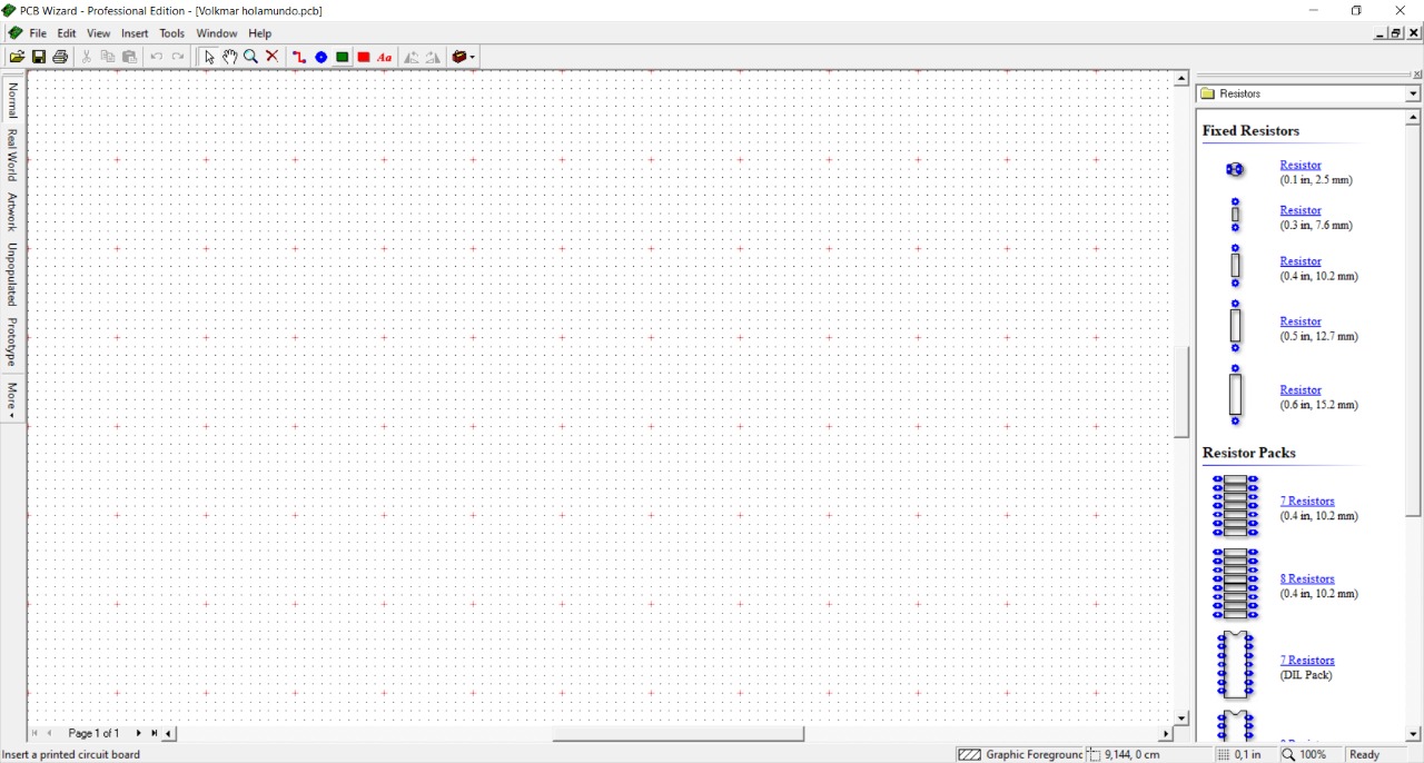
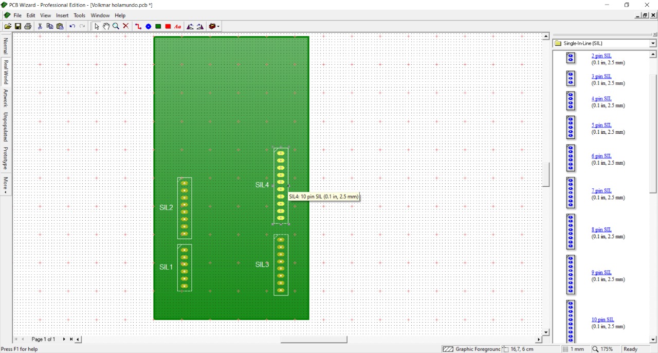
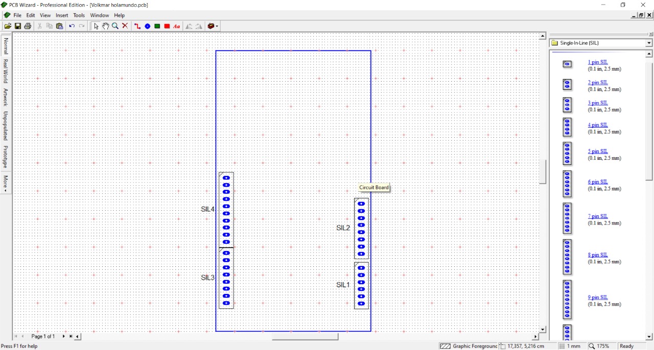
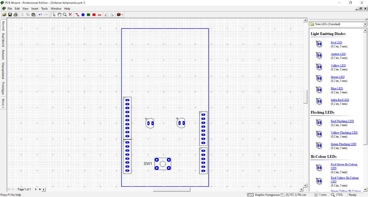
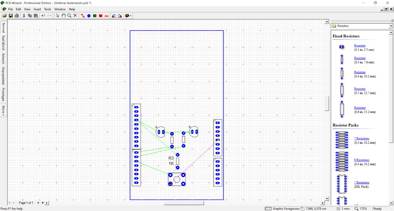
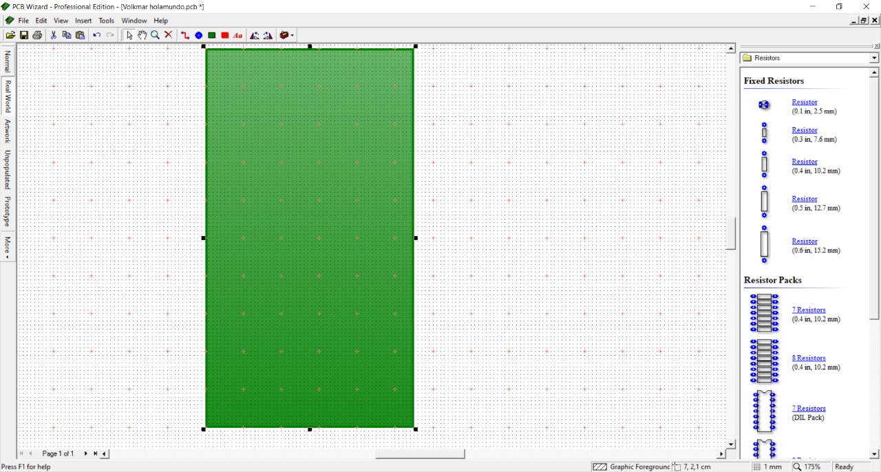
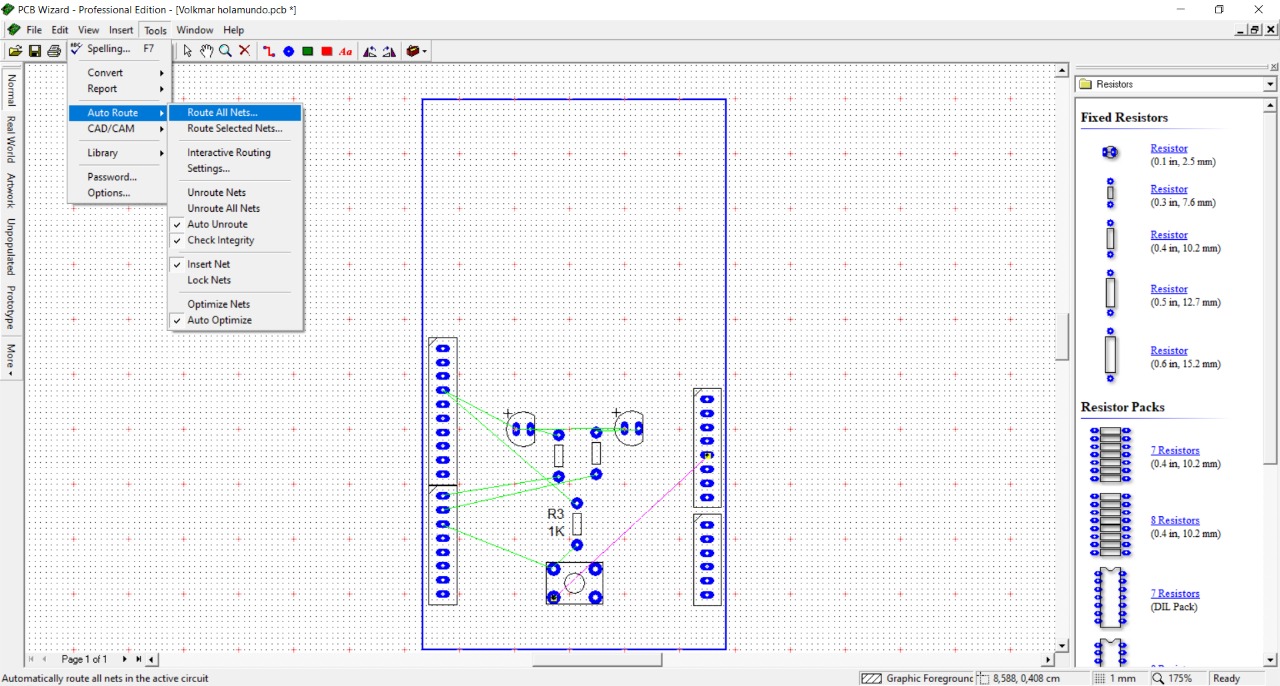
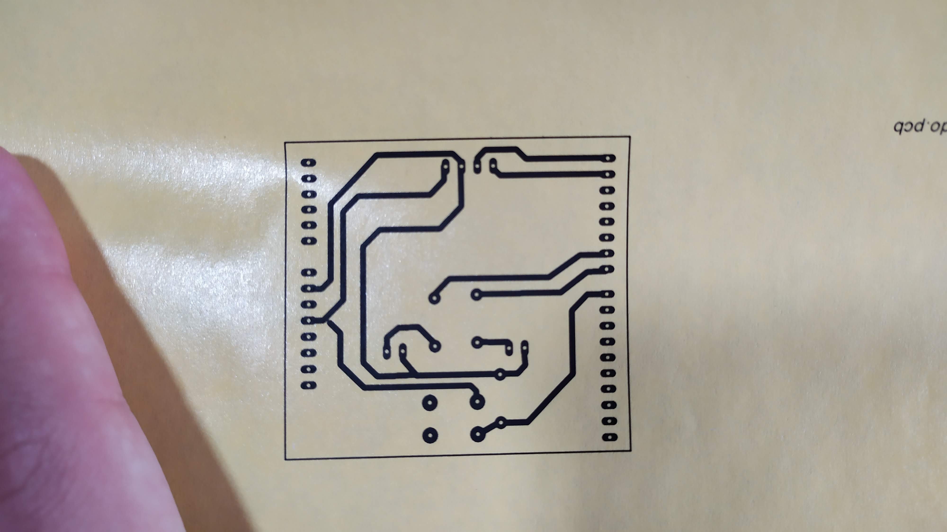
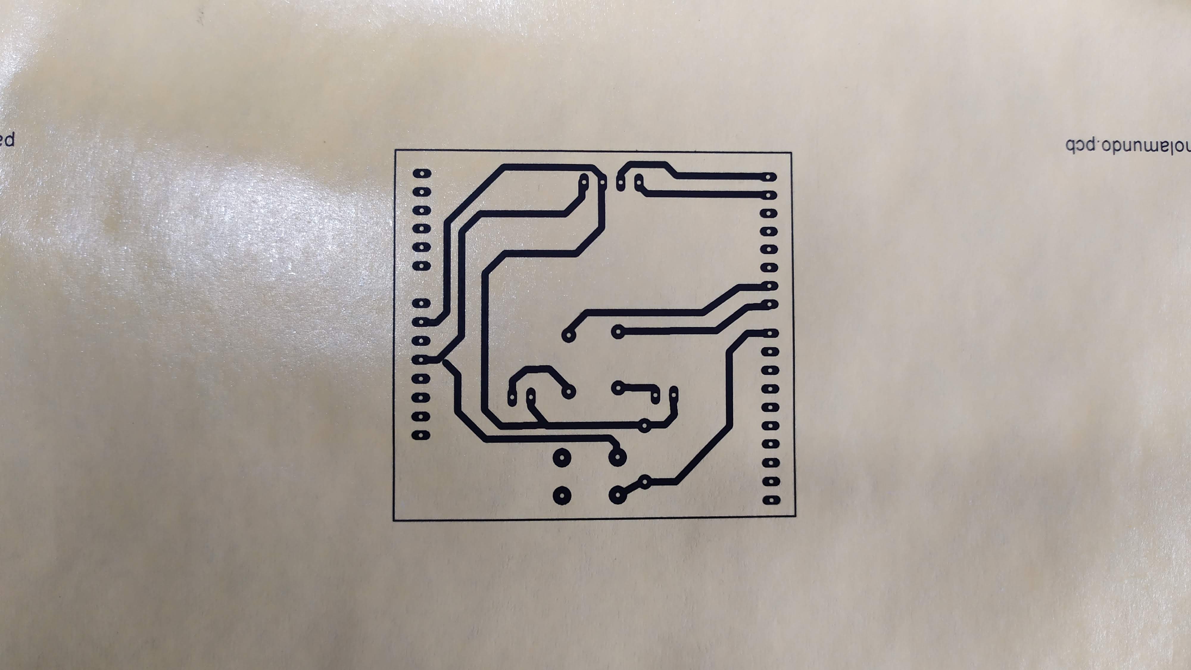
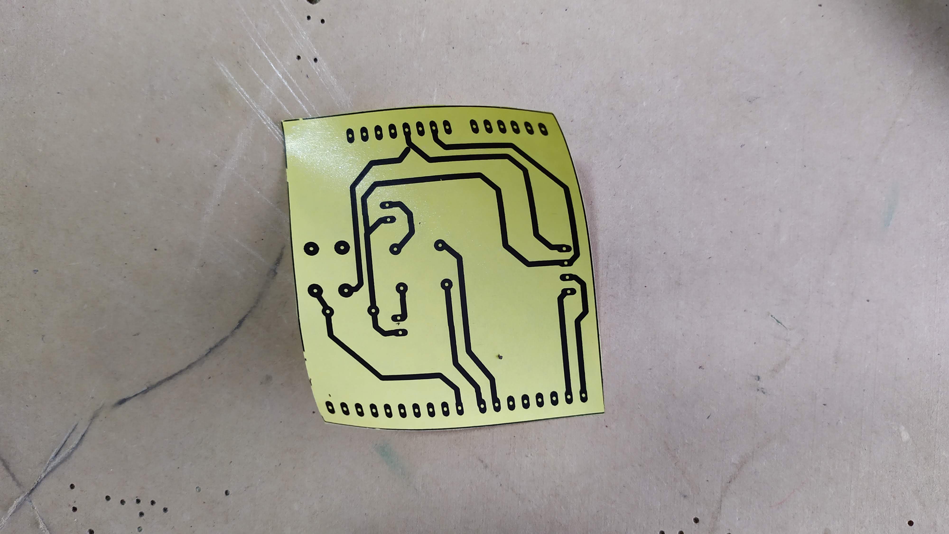
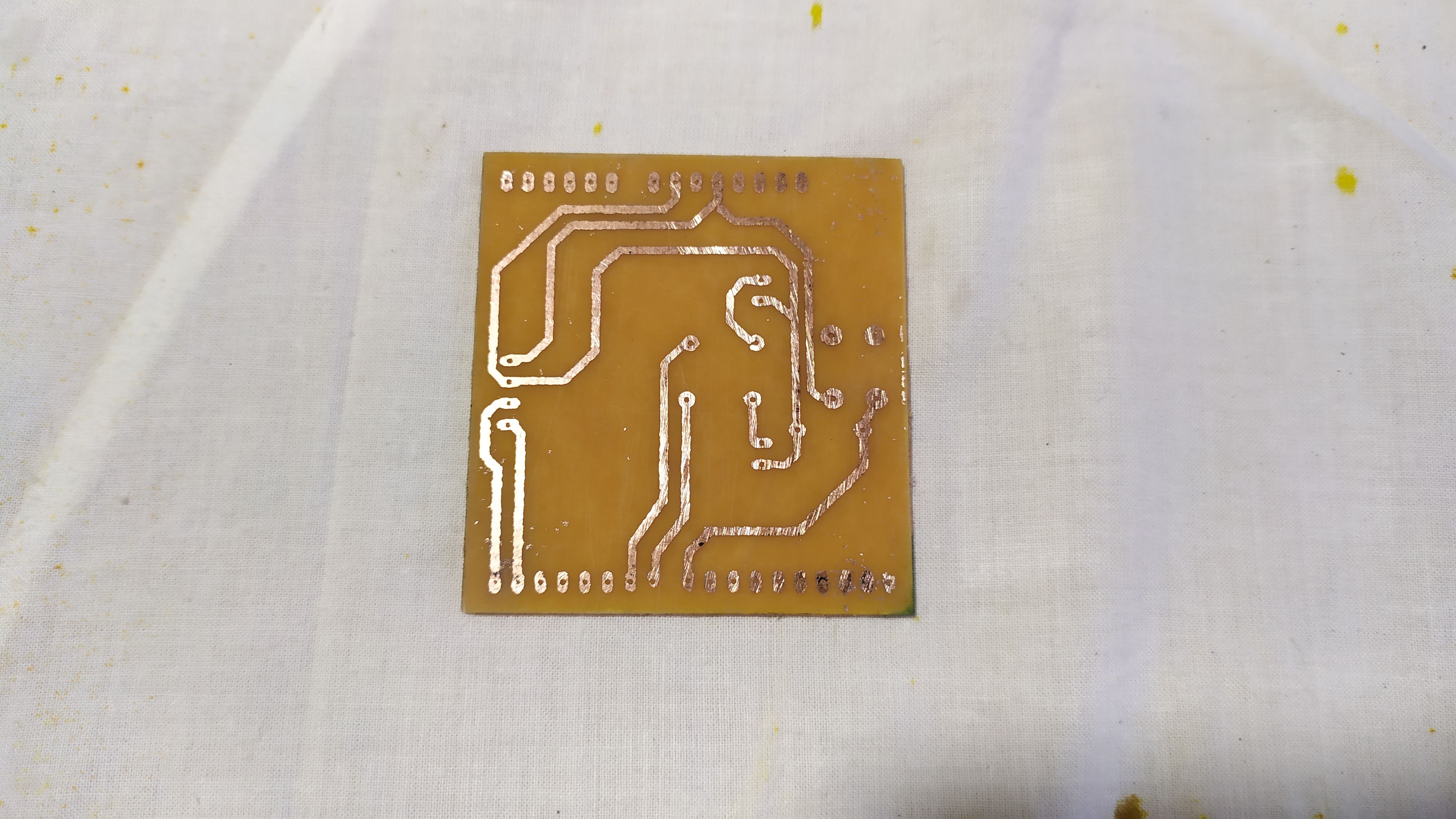
- In the PCB Wizard program the design was created based on the measurements of the PCB board available.
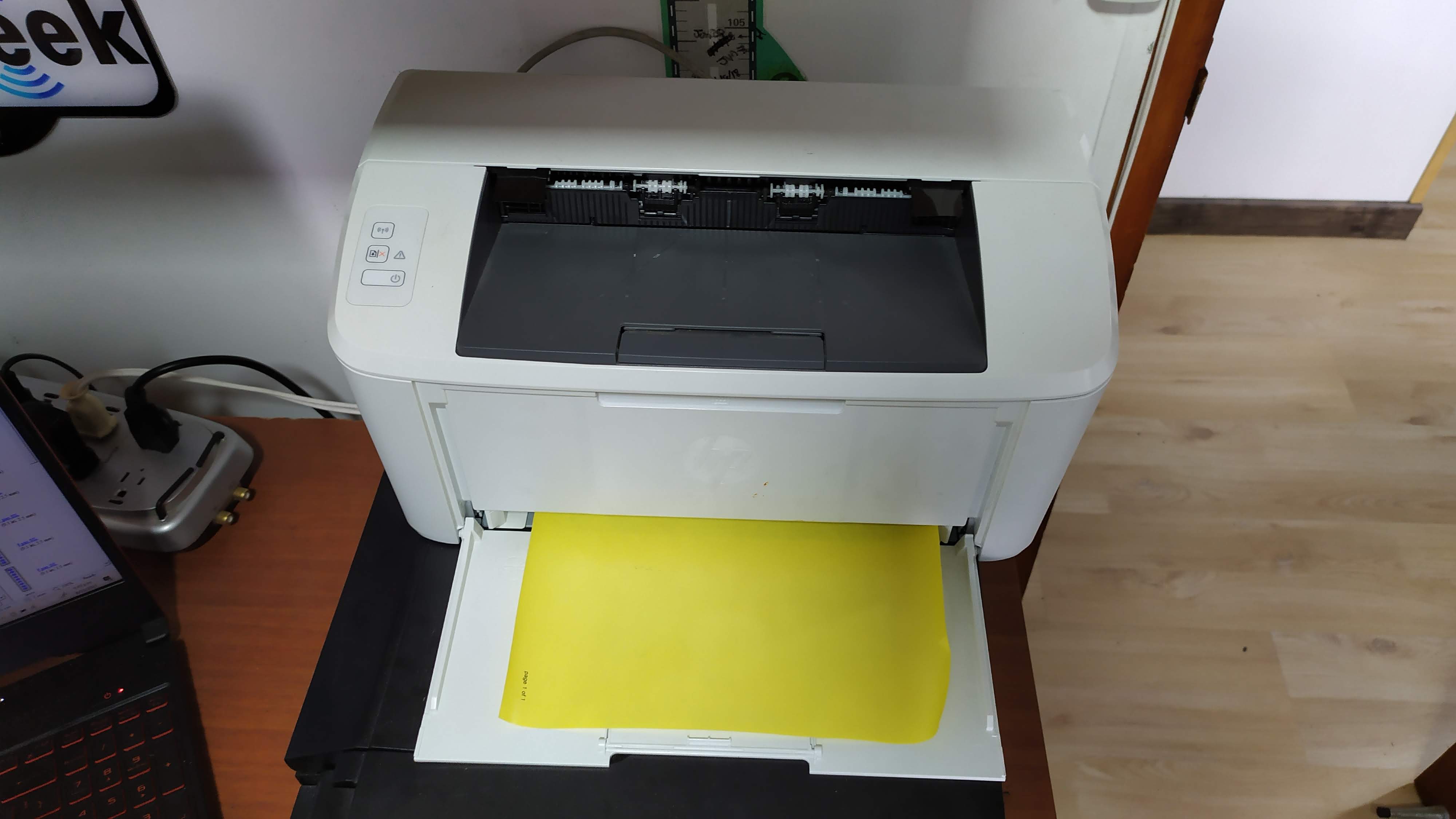
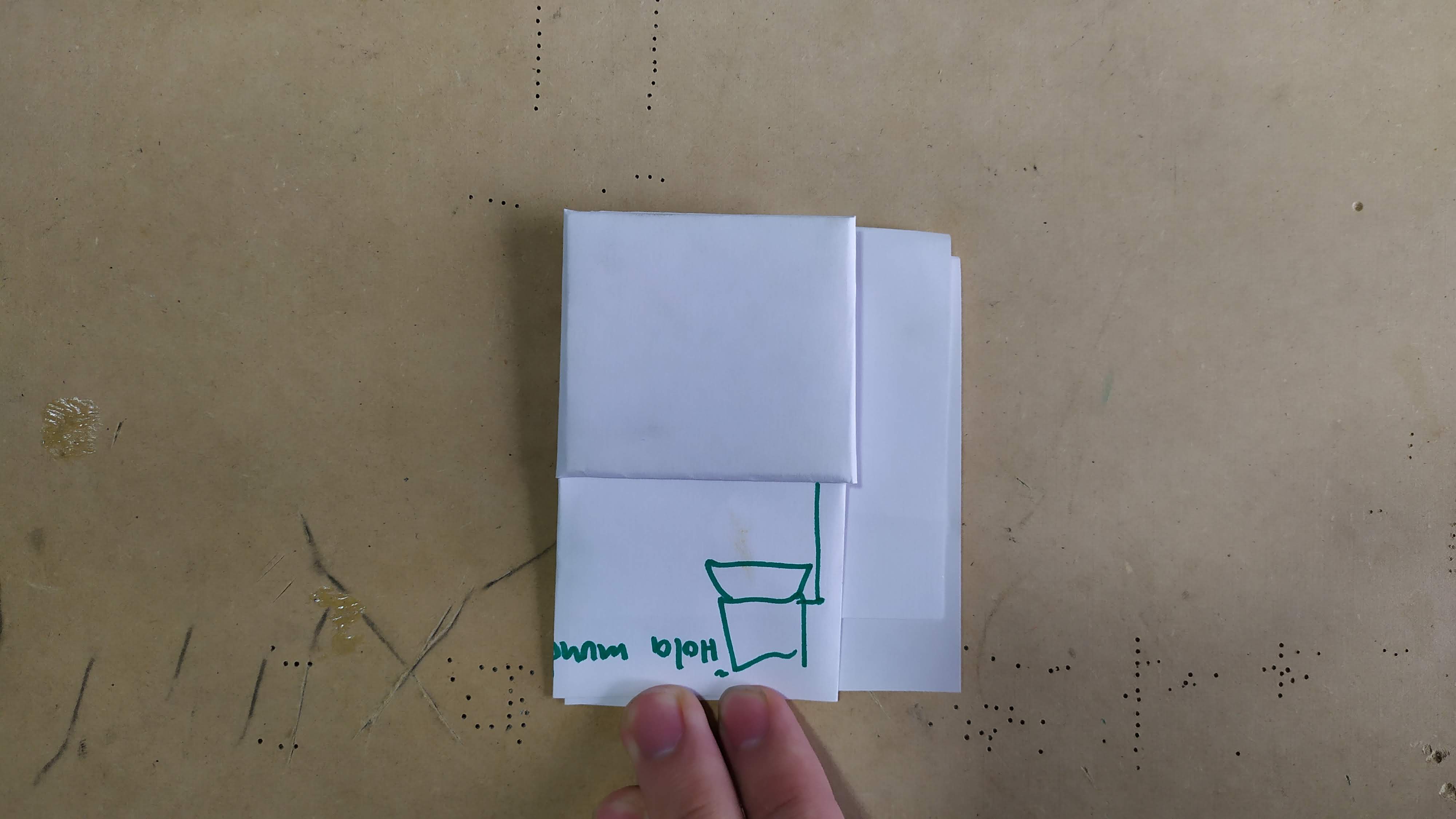
- It is printed on a transfer paper (the printing or design of the circuit is upside down to be able to paste it and that it is on the right side)
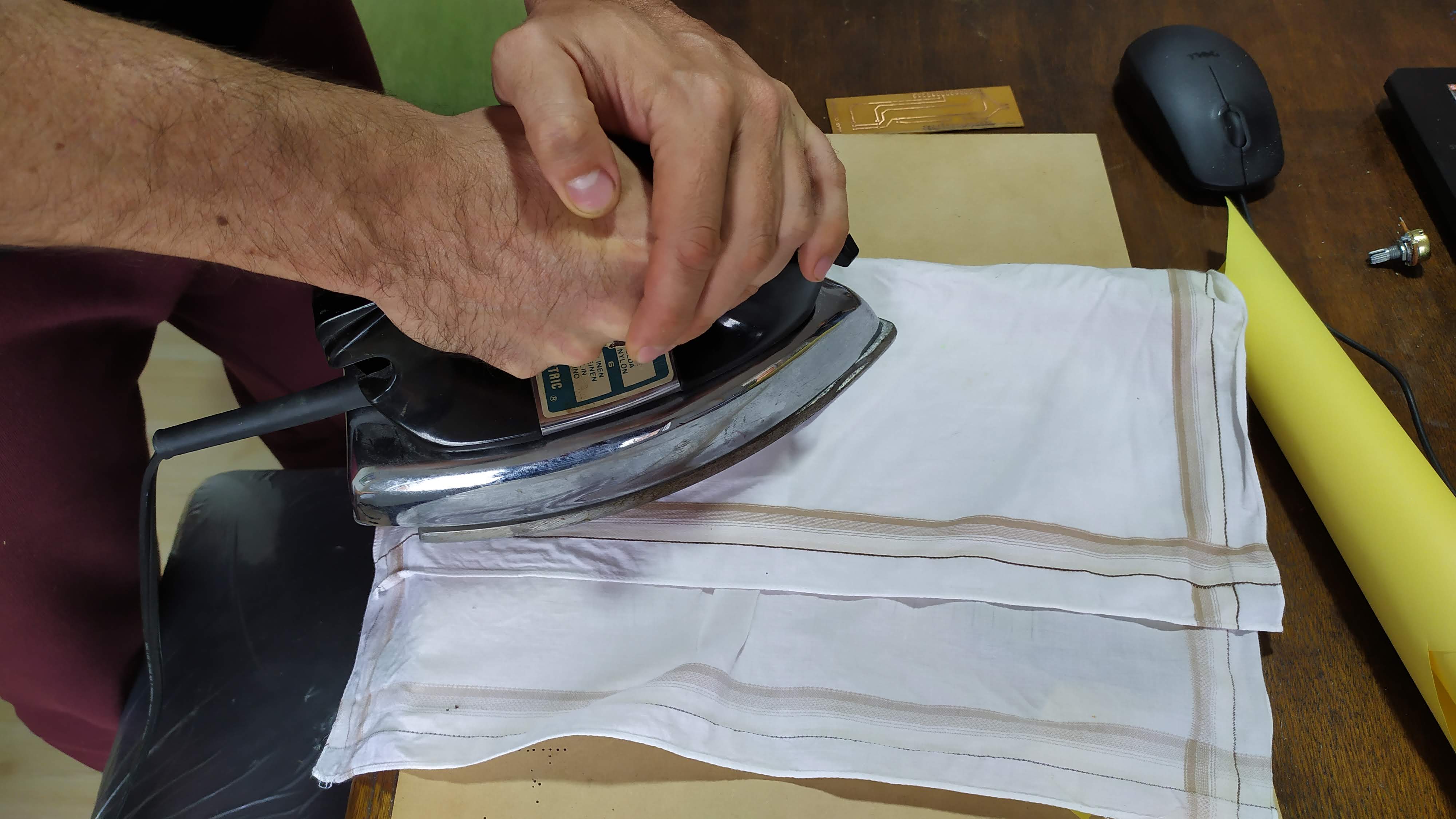
- Glue it to the board and use heat for about 10 minutes to transfer the ink to the board.
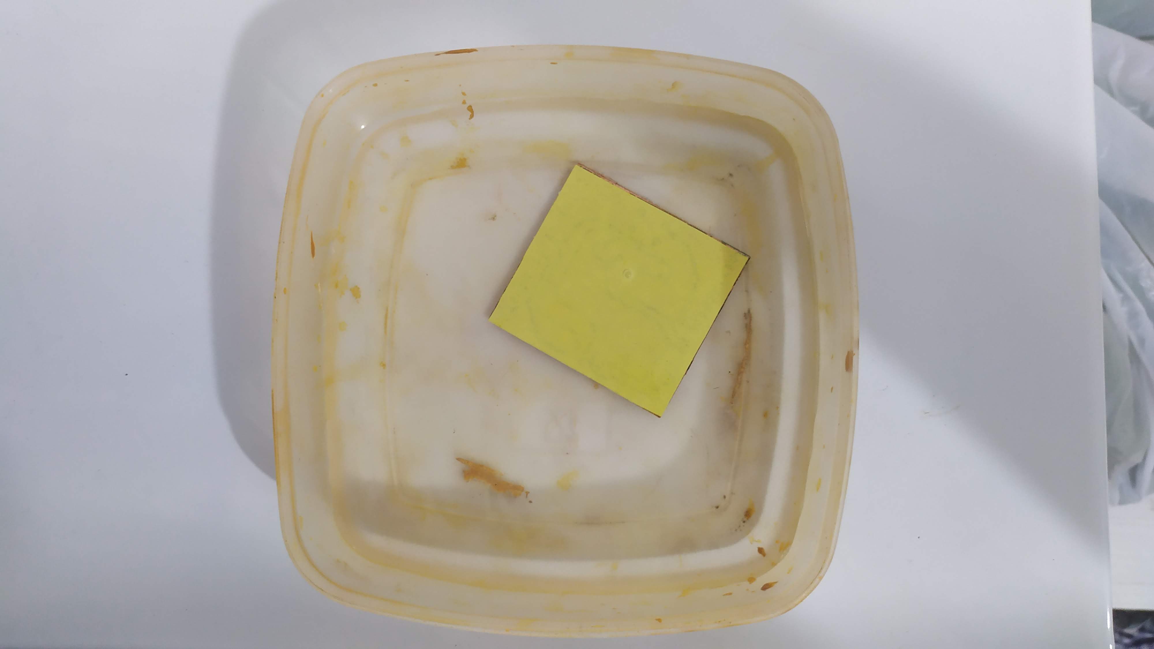
- Remove the excess paper and wash it.
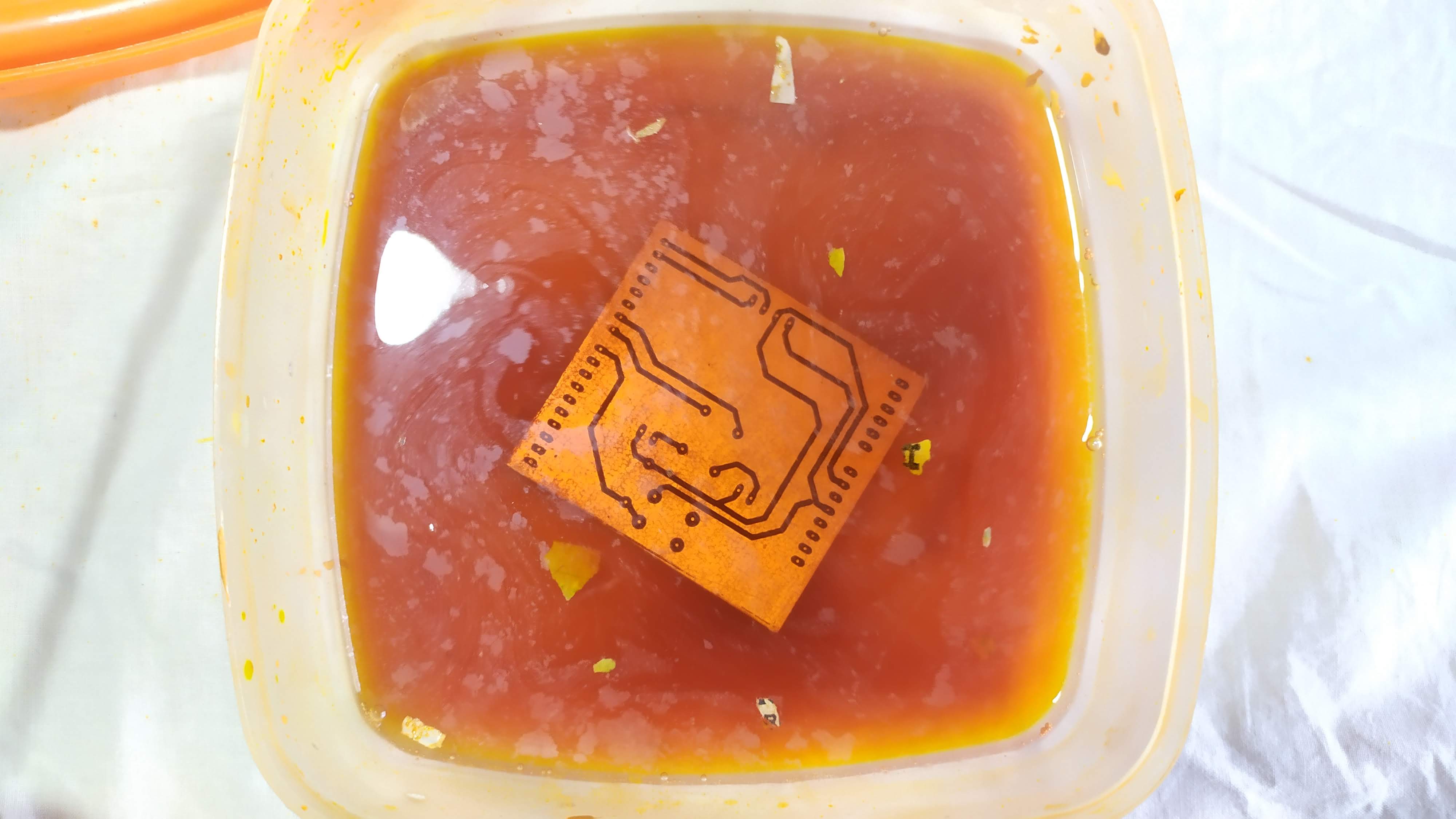
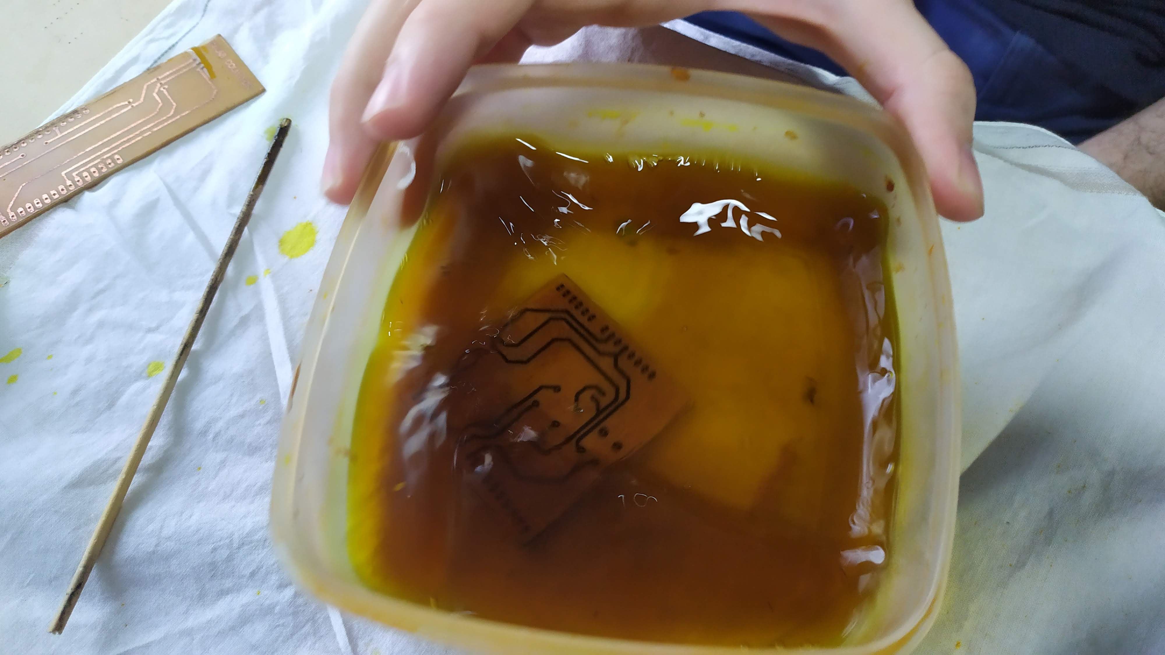
- Dip for the necessary time in ferric chloride until the excess copper is removed.
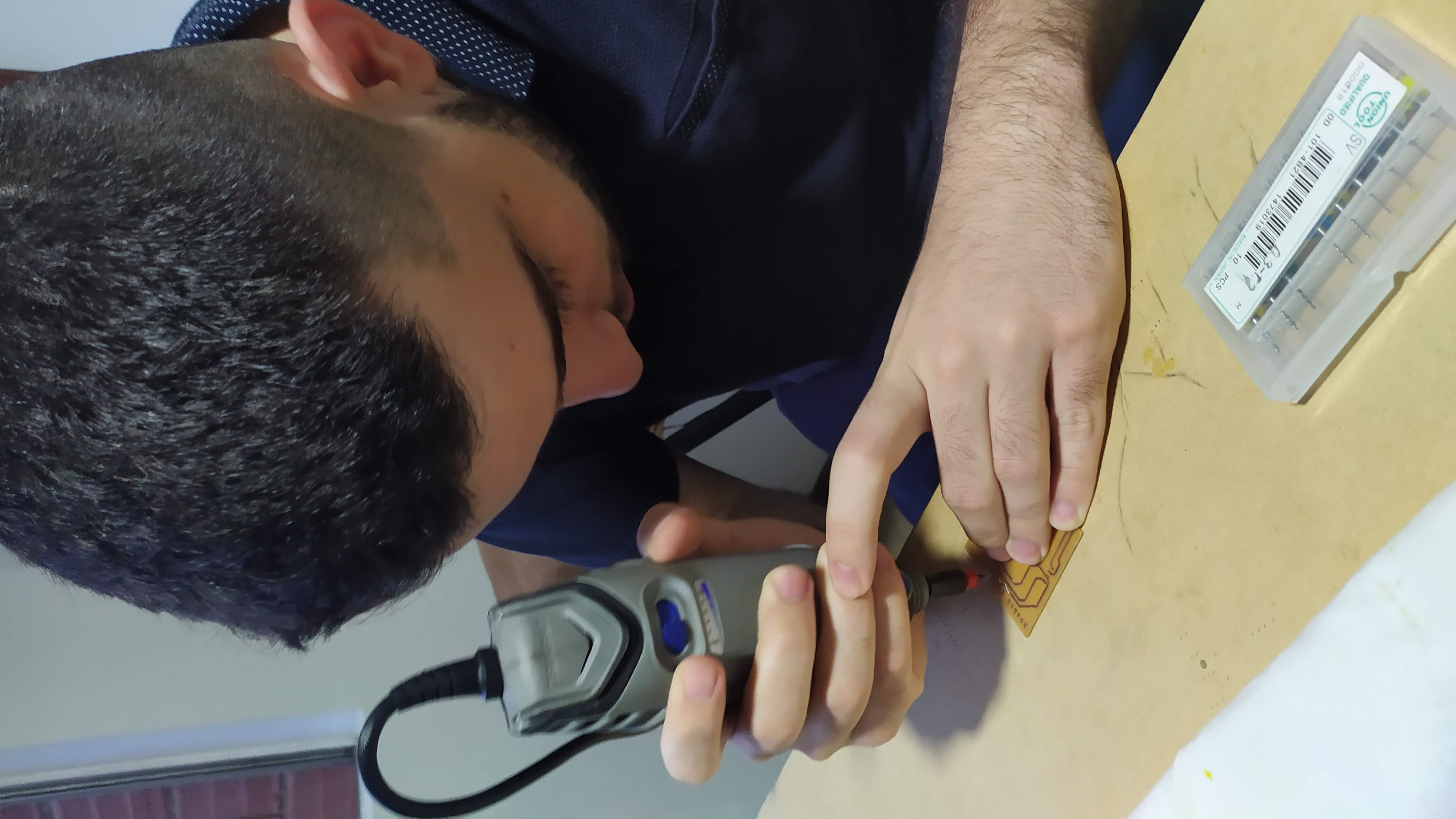
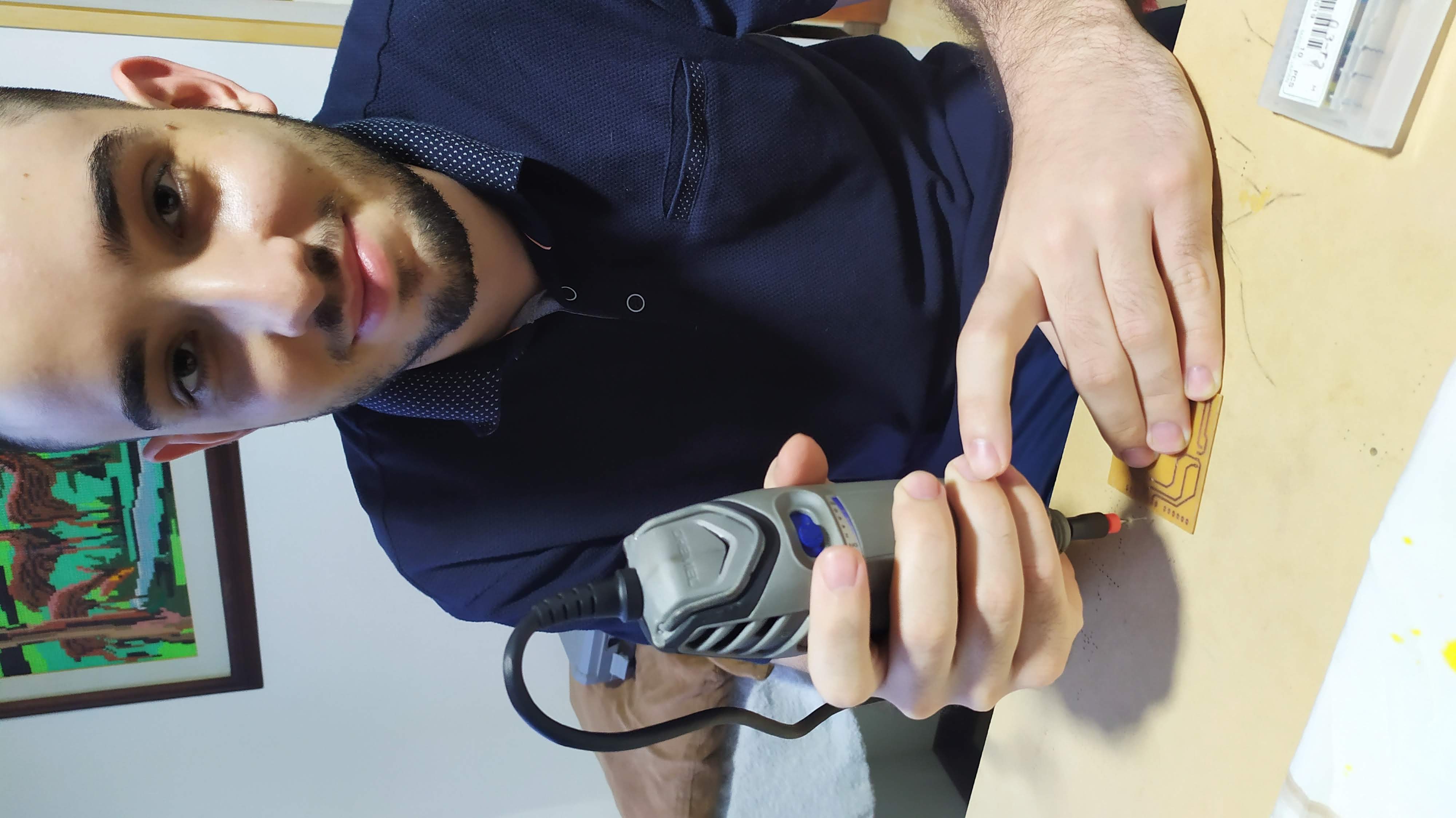
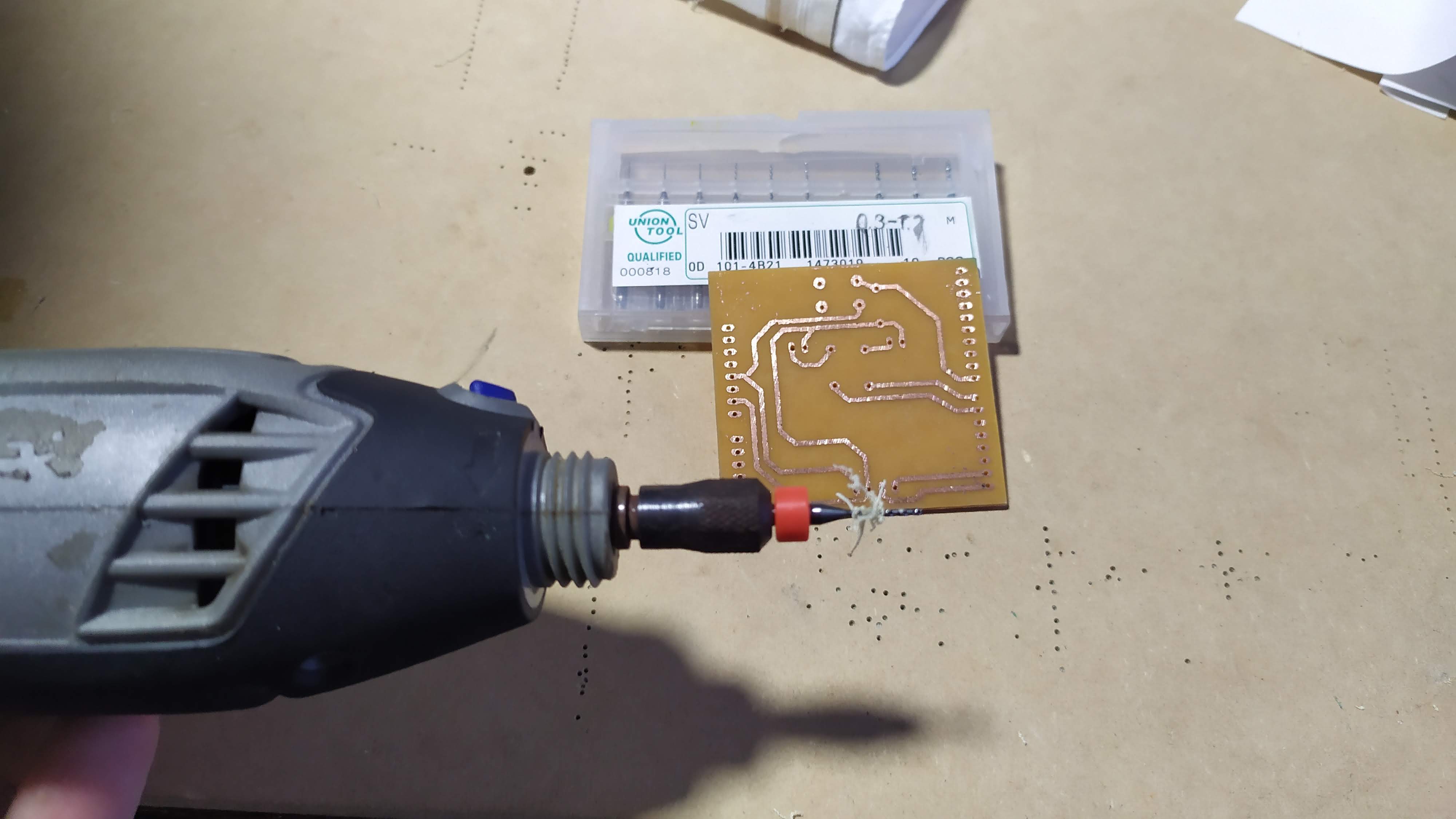
- A motortool is used to open the perforations to place the ESP32
prototyping and design
Almost any electronic device nowadays includes a key, button, pushbutton or switch. Arduino projects are no exception and virtually any idea we develop will have at least a couple of buttons. In this tutorial we will talk about how to connect a button to the arduino and how we can correctly process the signals they send. We will also see how to do more advanced applications with buttons, for example: how to detect long presses, double or triple click, etc. Translated with www.DeepL.com/Translator (free version)
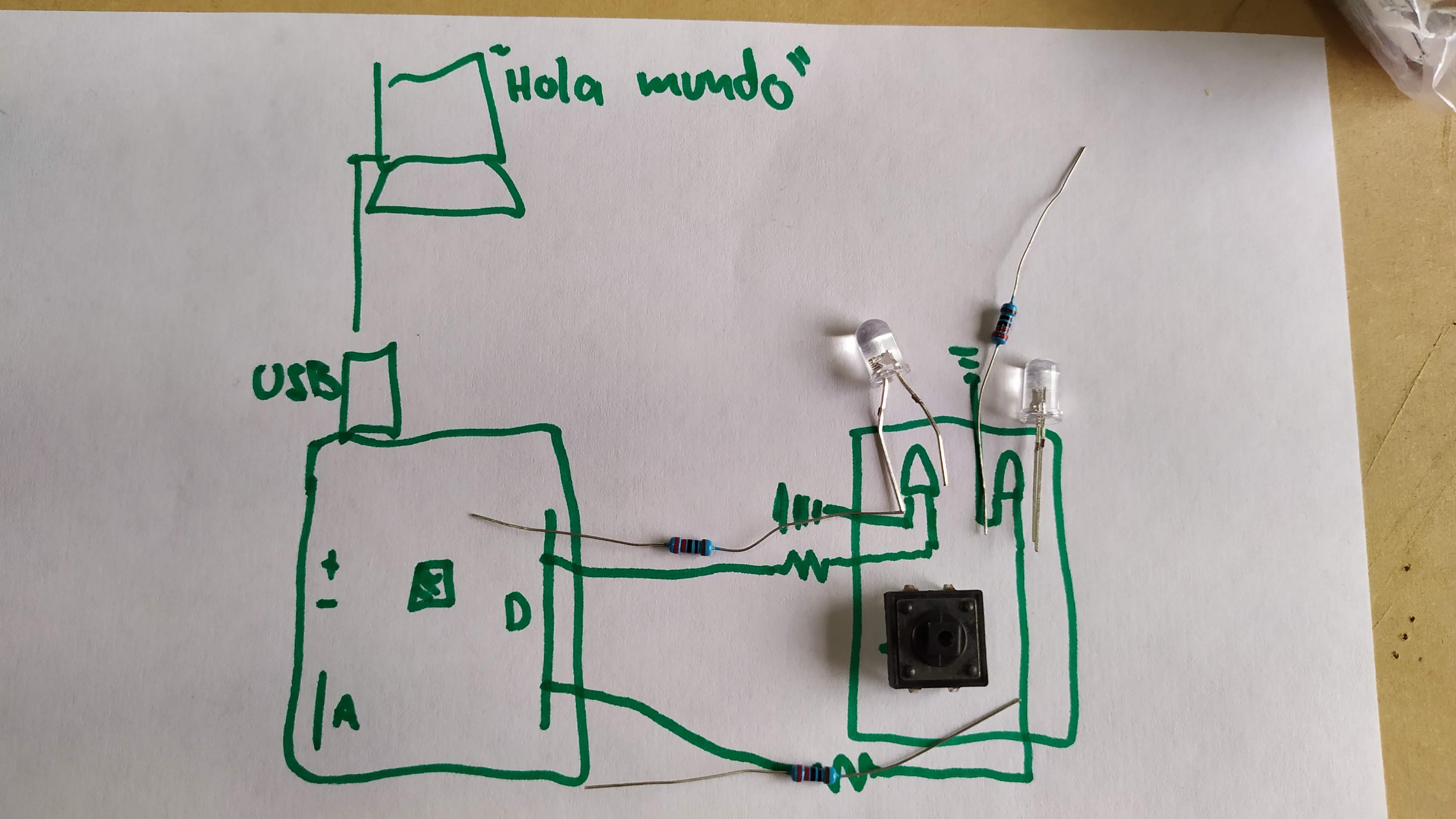
Materials needed for the exercises
To complete the exercises proposed on this page we recommend acquiring the following materials:
-Arduino Uno R3 or compatible
-Protoboard
-10 K ohms resistors
-Push-buttons or push-buttons
-We will use the led on pin 13 of the arduino to perform the practices without the need to connect external leds.
-SSD1306 OLED display
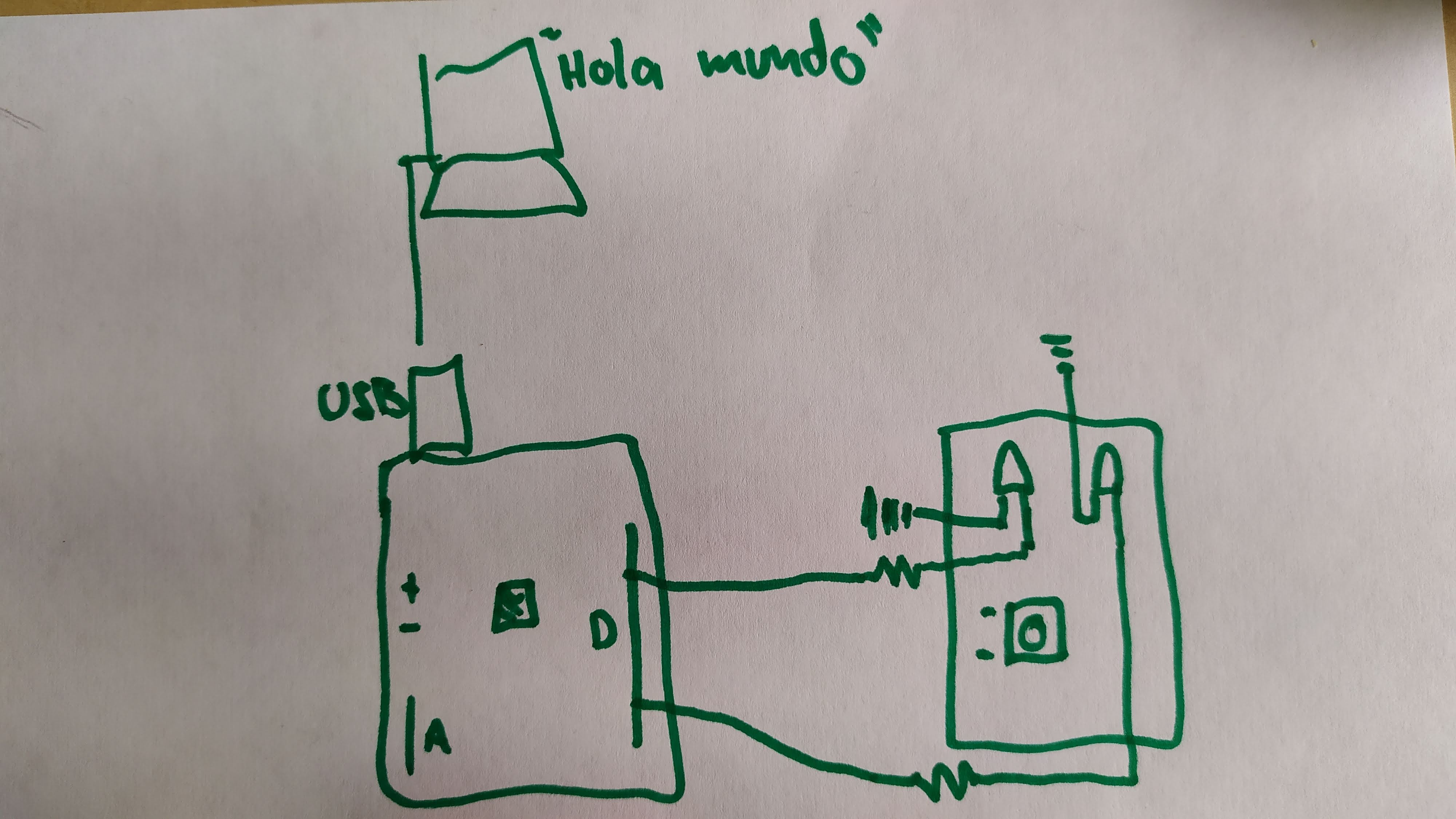
How to connect a button to the arduino?
To connect a button to the arduino it is convenient to keep in mind certain points:A button can be connected to any arduino pin (digital or analog, since analog ones usually work as digital as well).
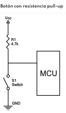
There are two possible configurations: with pull-up resistor or pull-down resistor.
We will configure the selected pin as digital input.
We must take into account the bounces and electrical noise in the software.
It is necessary to use a pull-up or pull-down resistor, either internal or external.
The two ways to connect a button to the arduino are shown in the following diagrams:
Botón con resistencia pull-up
Botón con resistencia pull-down
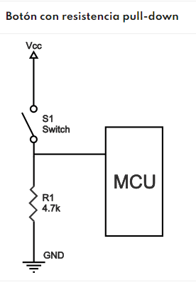
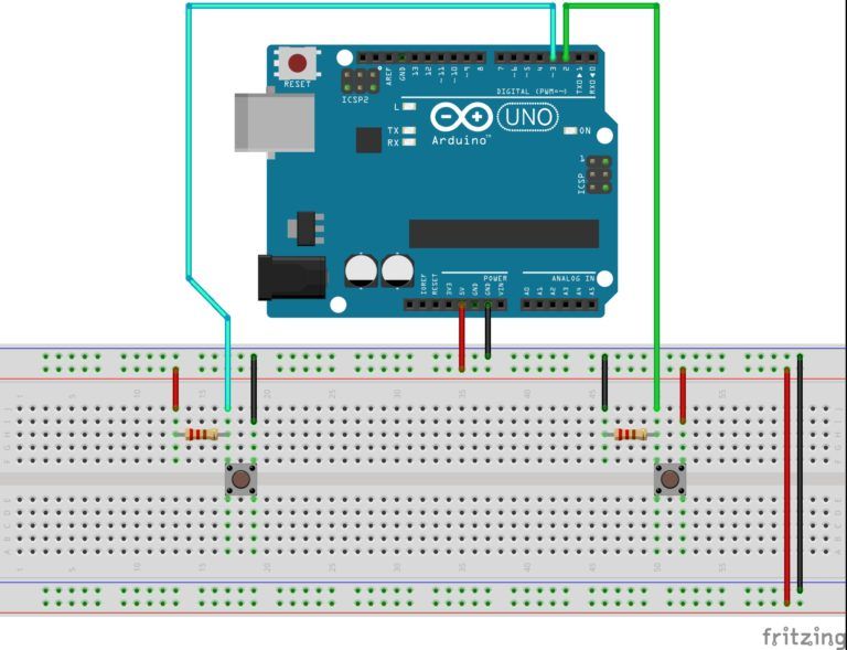
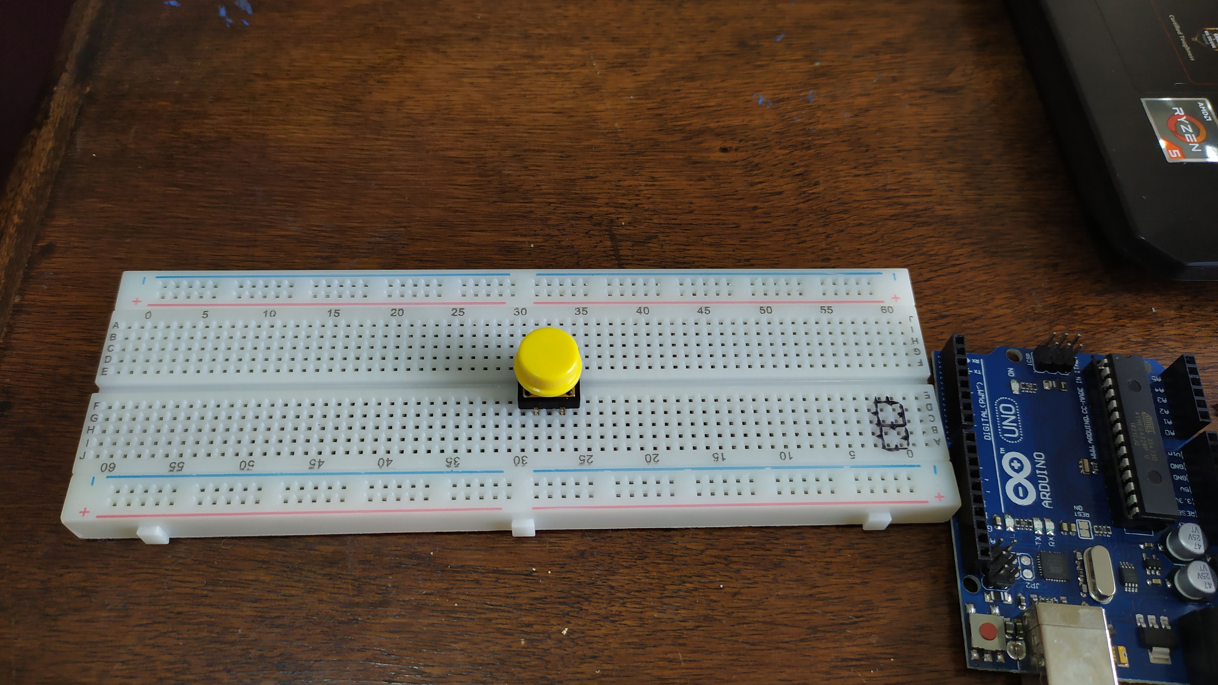
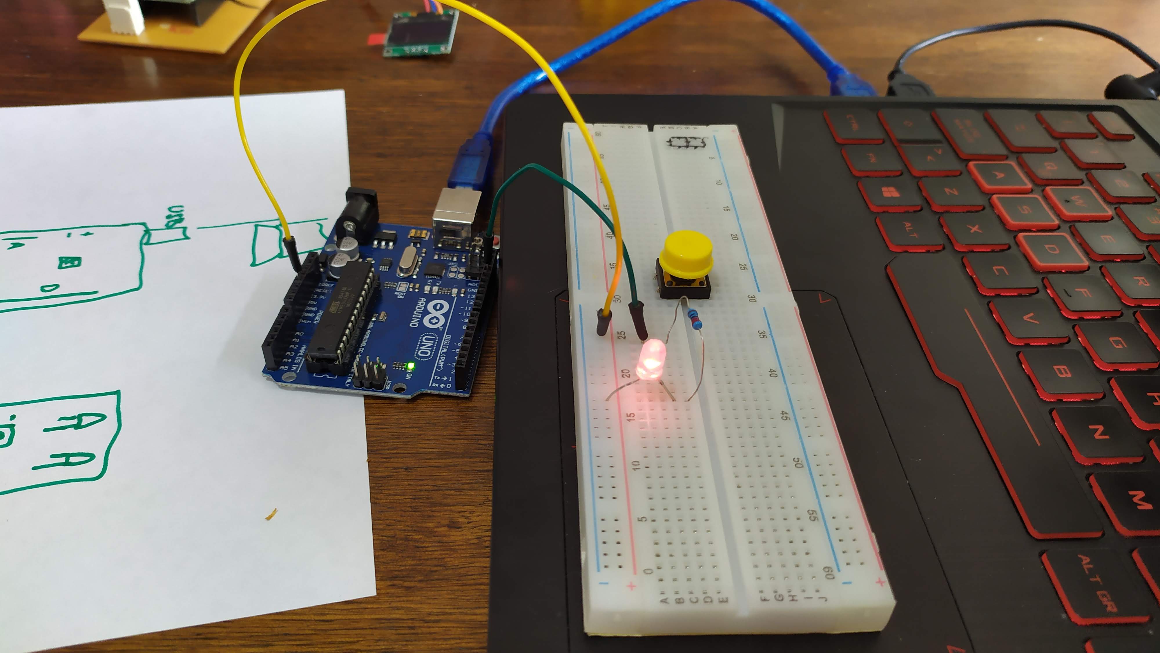
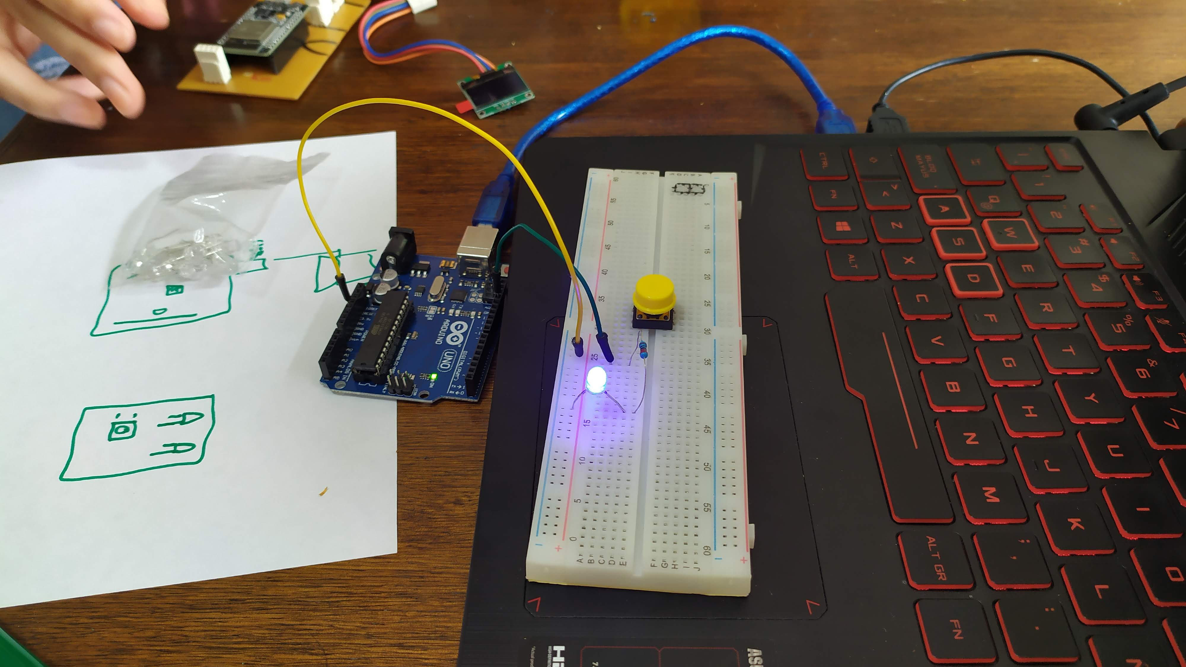
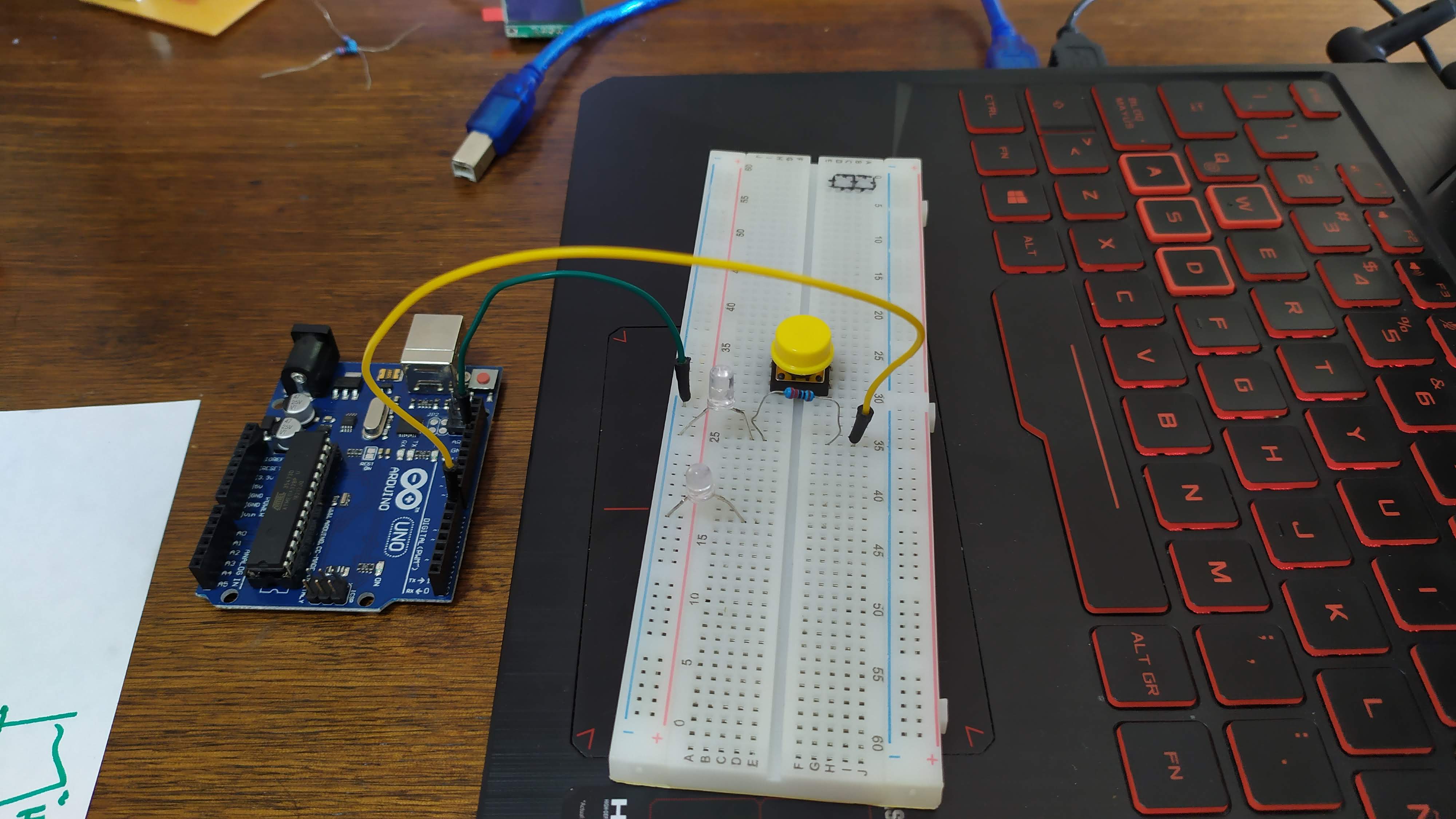
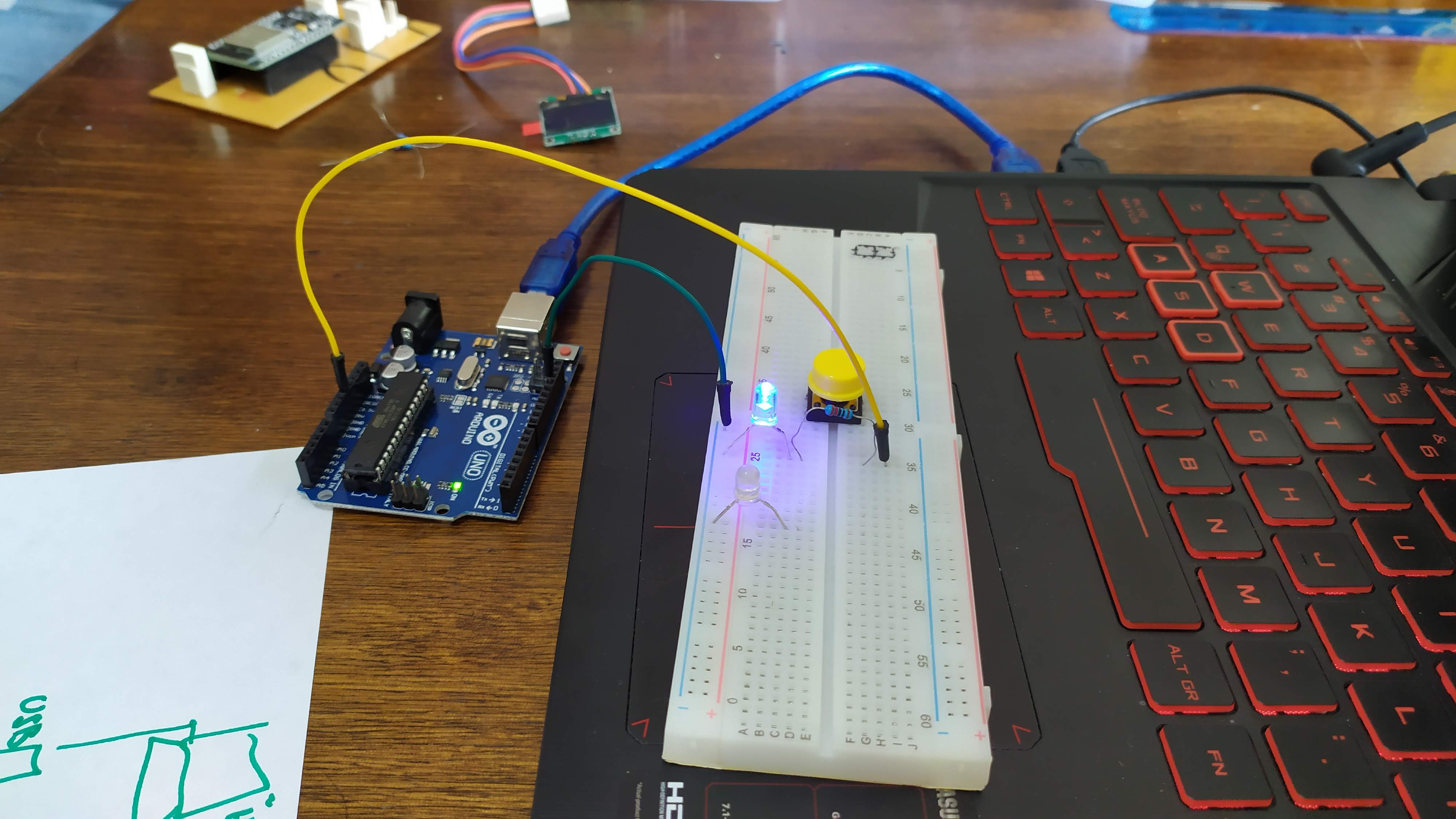
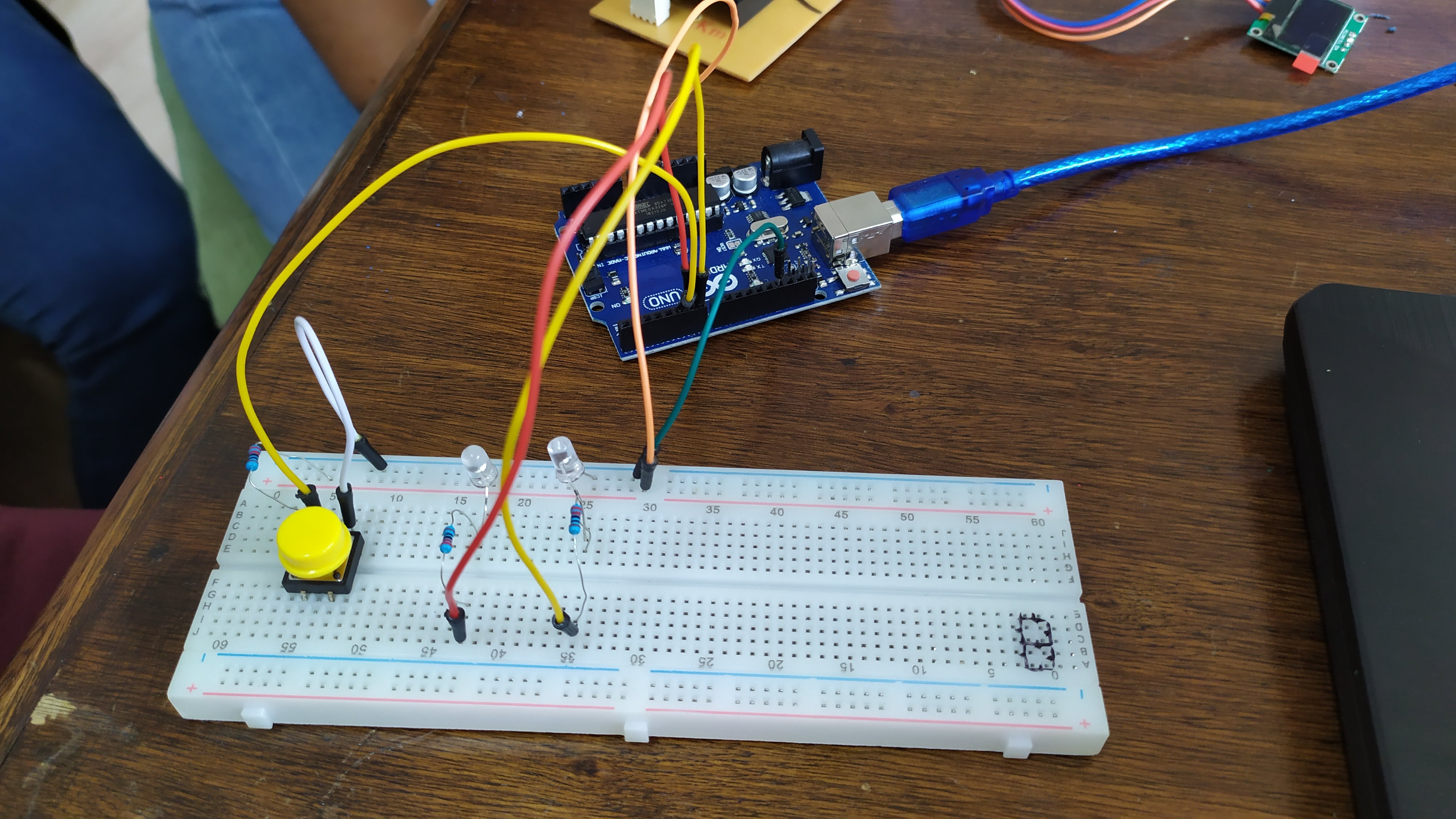
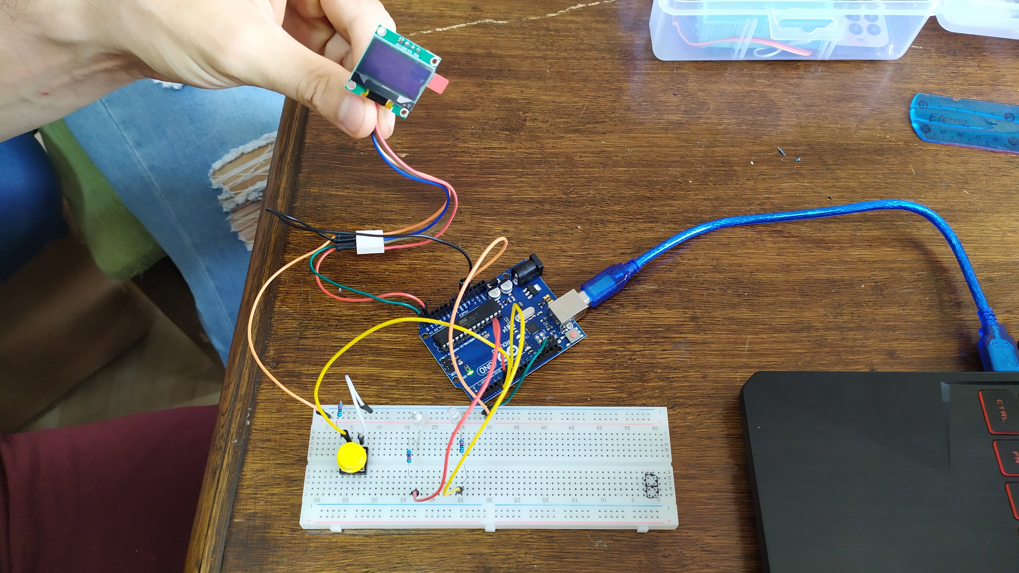
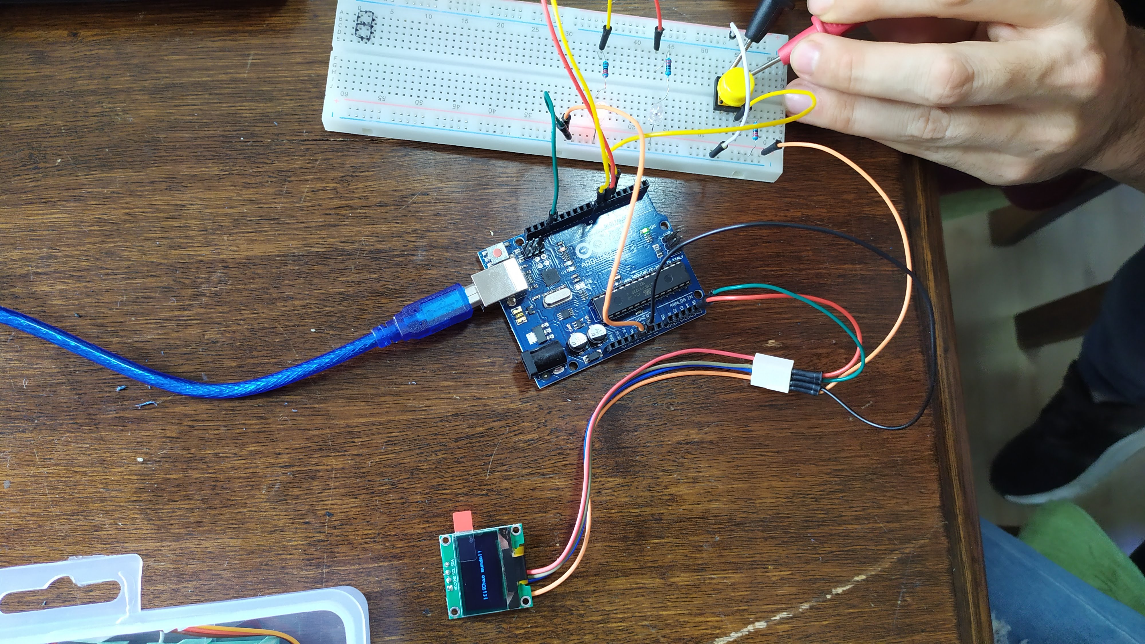
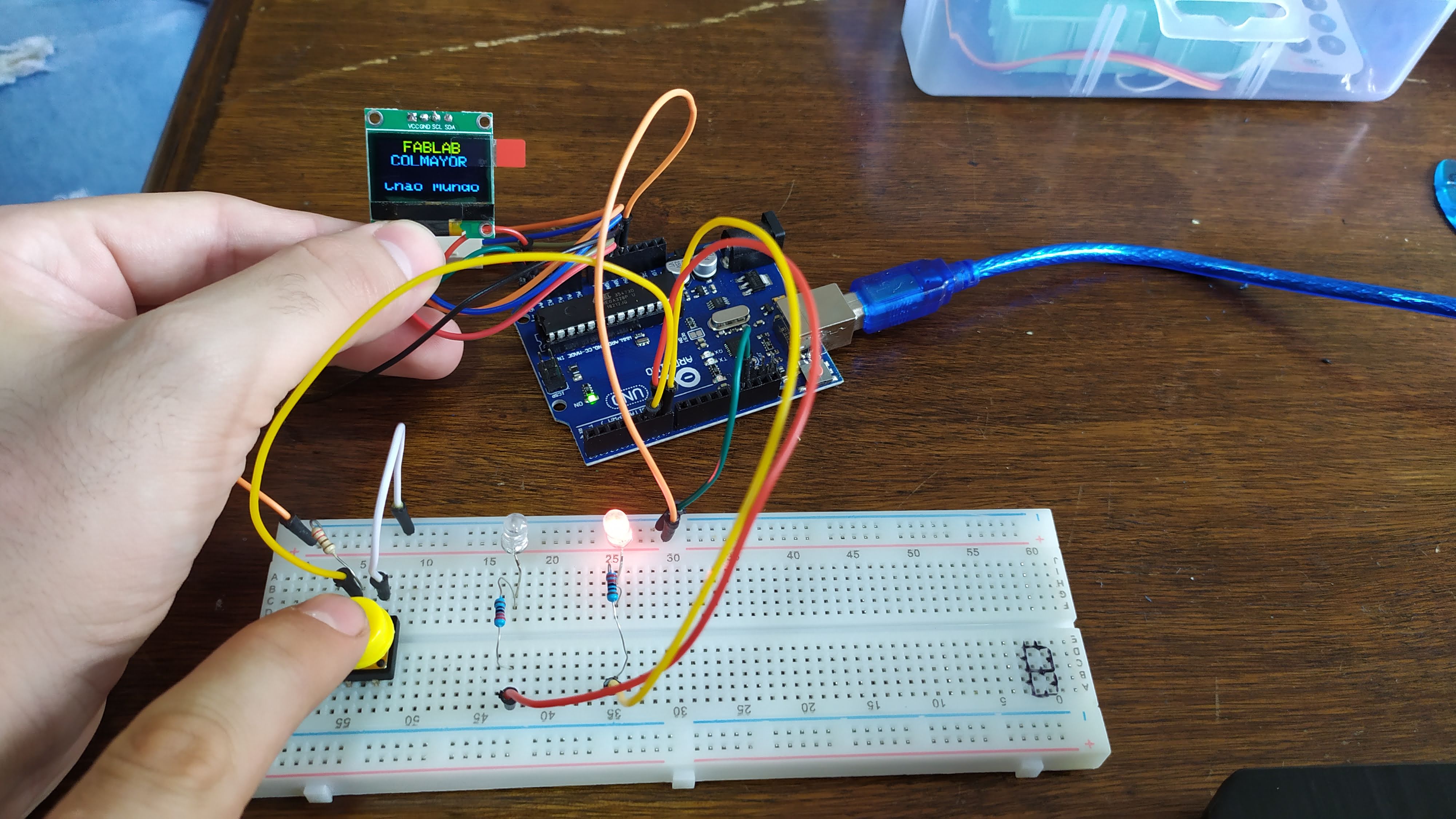
Seen on the breadboard it would look as shown below, with the button placed on the left side of the breadboard being connected with pull-up, while the right side is connected with a pull-down resistor.
prototyping on breadboard
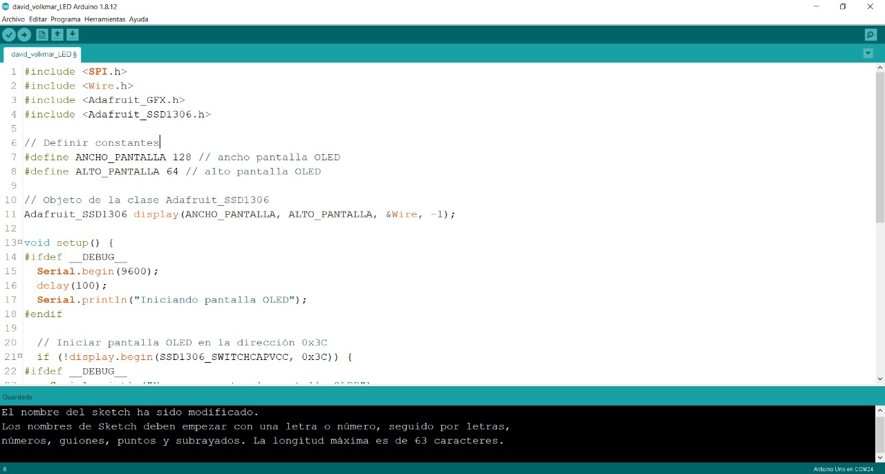
Ardunio Code
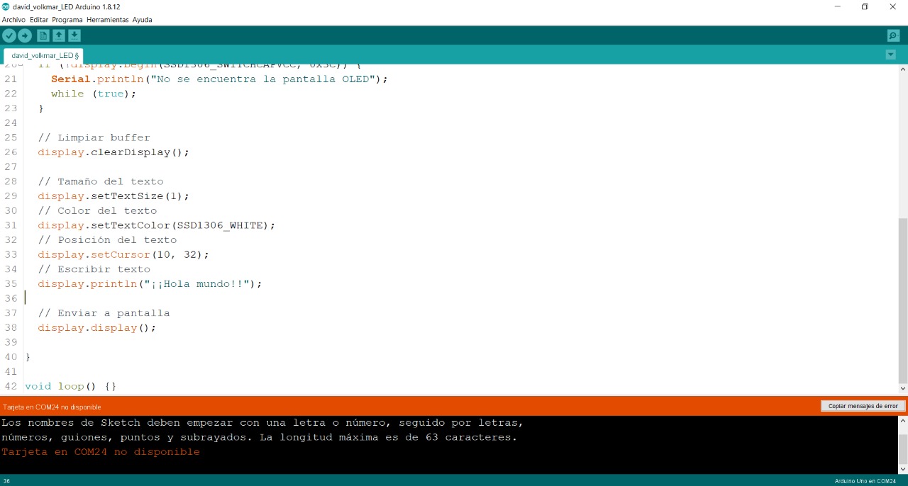
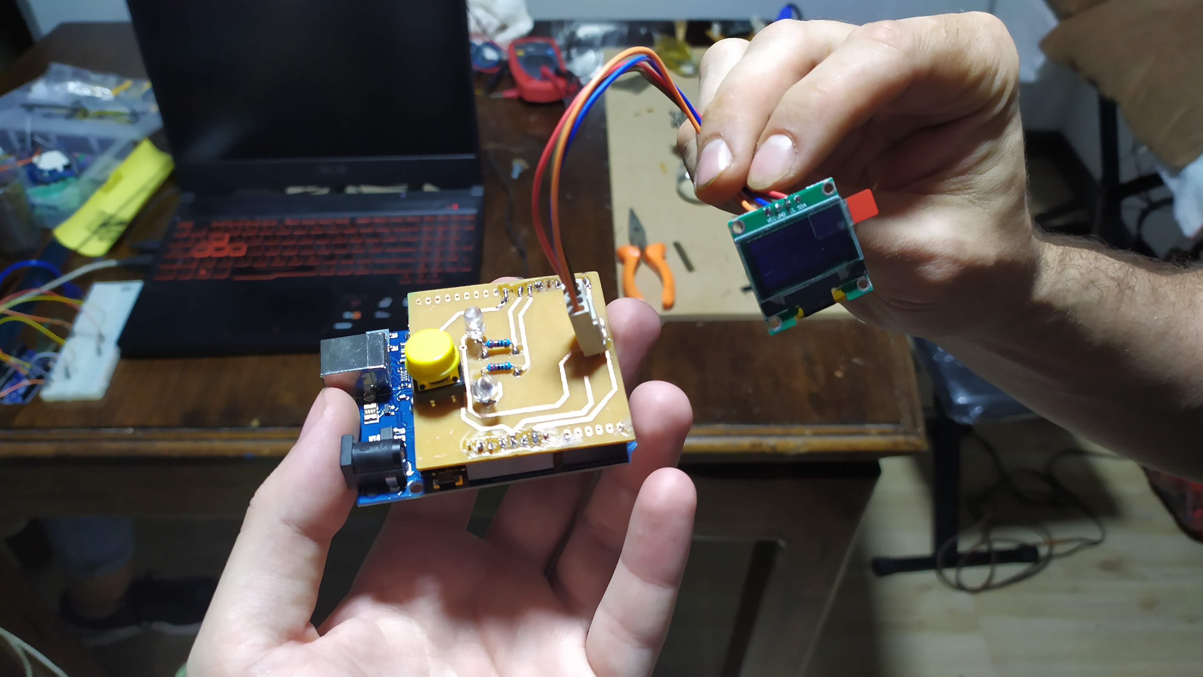
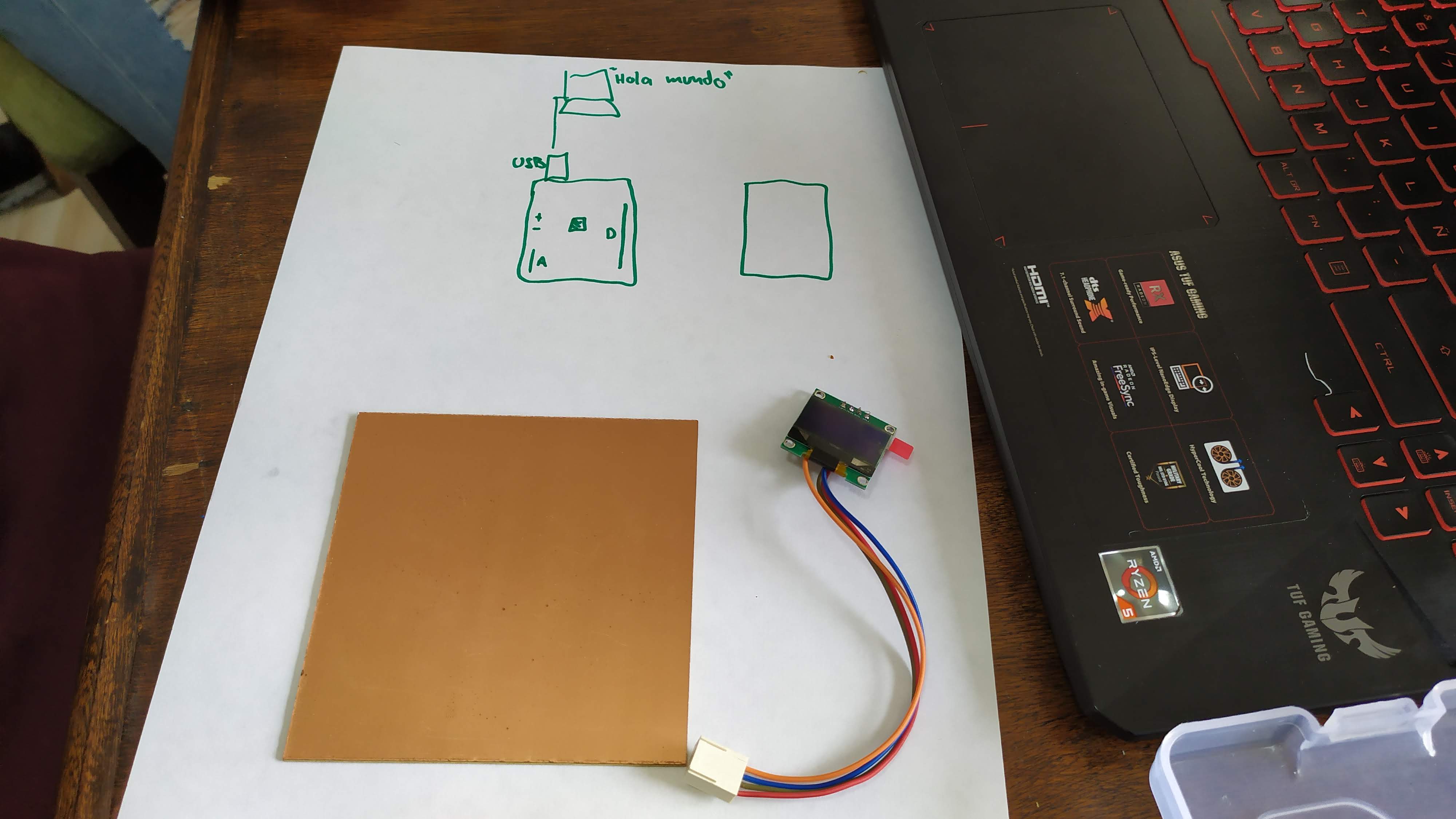
electronic board design
for the design of the electronic board we used the PCB Wizar program. we took the measurements of all the pieces that needed to be joined and that at the moment of drilling to solder the components it would fit correctly.
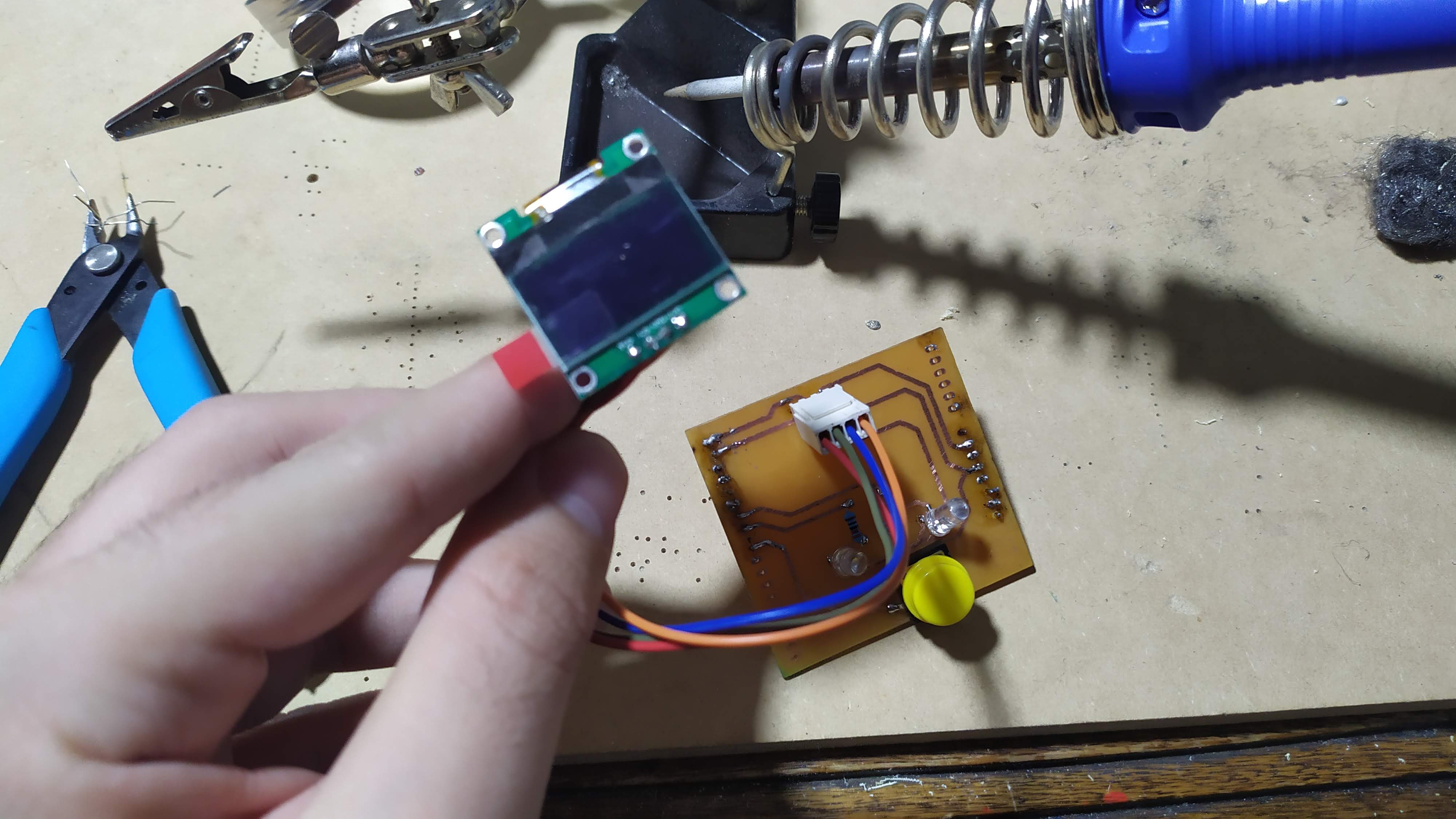
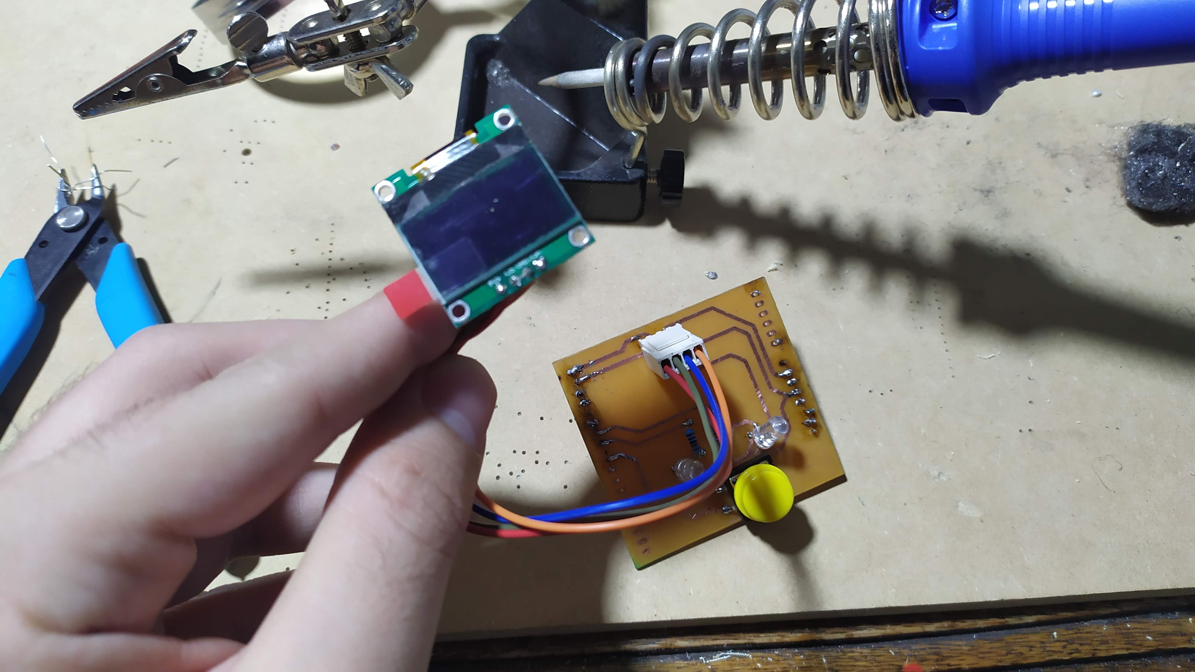
SSD1306 OLED display
Before we start, it is necessary to clarify what OLED stands for. It stands for Organic Light-Emitting Diode, which translates as organic light-emitting diode. When I read it for the first time, I didn't really understand what organic meant. I associated it with something living, with organisms. And it actually has a lot to do with it. OLED displays are composed of sheets of organic materials such as carbon (hence the name organic diode). These sheets emit light when electricity is applied between them. Translated with www.DeepL.com/Translator (free version)
One of the advantages of OLED screens over LCD screens is that they do not require a backlight or filters.
Then we will see that not having a backlight is very important because it makes its consumption very low.
This makes OLED screens more energy efficient, easier to manufacture and much thinner. They can also be flexible and transparent.
SSD1306 controller for OLED display with Arduino and ESP8266
OLED displays are just that, displays. By themselves they do nothing. In order to display data and information on them, a driver is needed. It usually comes all assembled in a single module. This is how you will find it in electronics stores. However, it should be clear that in that module is the OLED display, the controller and the electronics needed for everything to work properly.
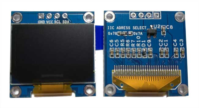
Normally these modules use a well known controller called SSD1306. But they can use other types of controllers. It is a powerful OLED CMOS controller. Basically what the SSD1306 does is communicate with the microcontroller to get the data and send it to the OLED display to draw that data. The communication between the SSD1306 and the microcontroller, either an Arduino or an ESP8266, is done via SPI or I2C. Generally, SPI communication is faster than I2C communication. Conversely, SPI communication requires more pins than I2C communication. In the end, one outweighs the other. You can choose faster communication at the expense of the number of pins, or you can choose to free up more pins at the expense of speed. It is still a personal choice. Because the SSD1306 is so versatile, you can find OLED displays with Arduino with different sizes and colors.
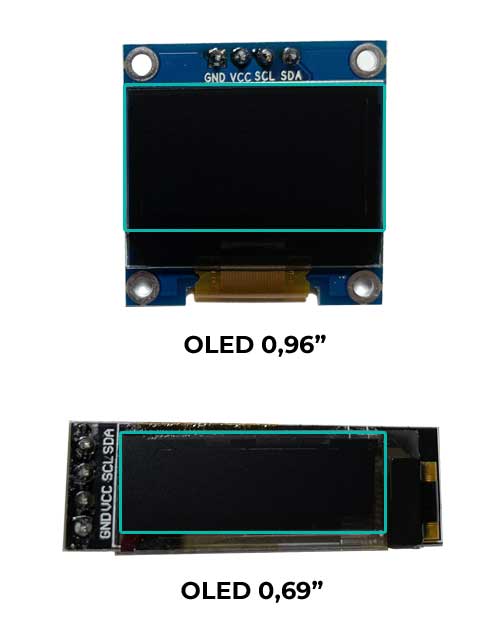
* There are even 1.30″ diagonal screens that use another driver such as the SH1106. There are also larger sizes.
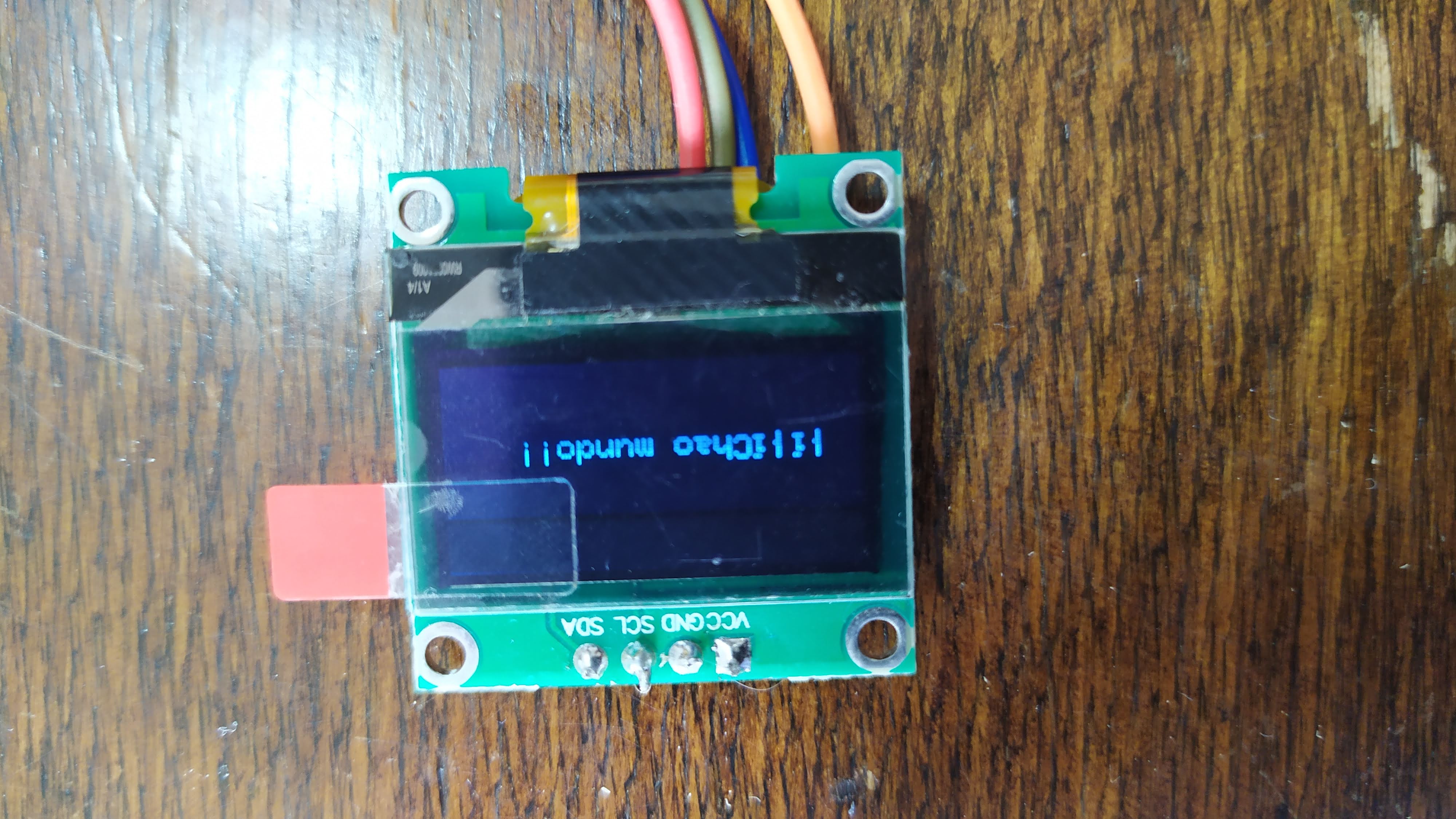
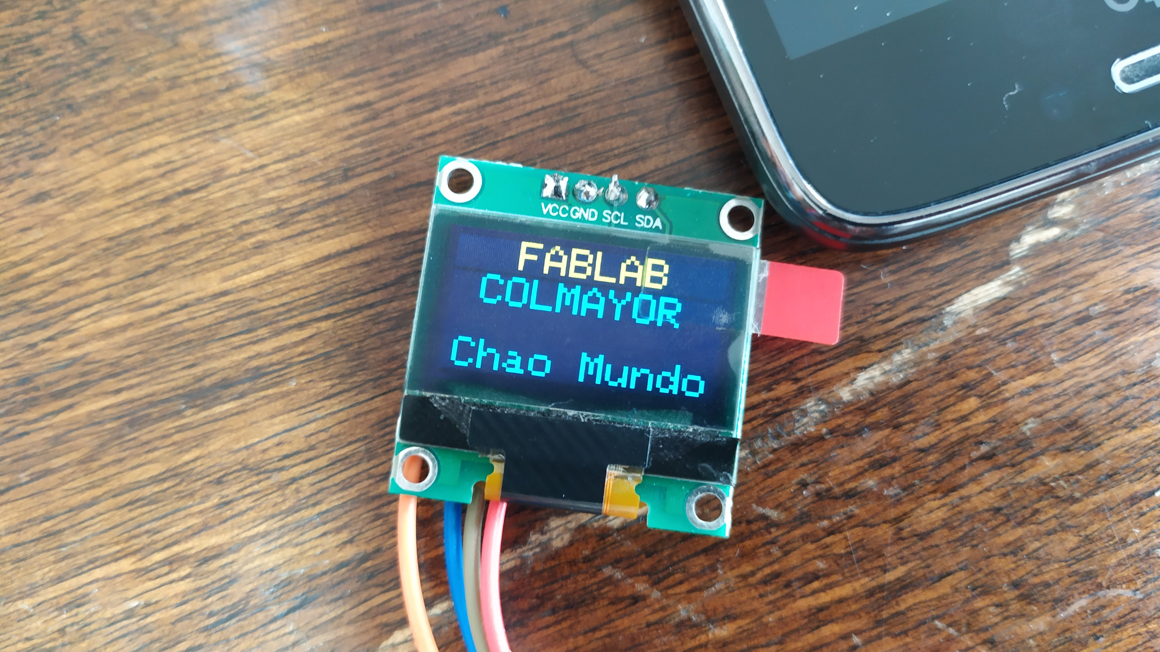
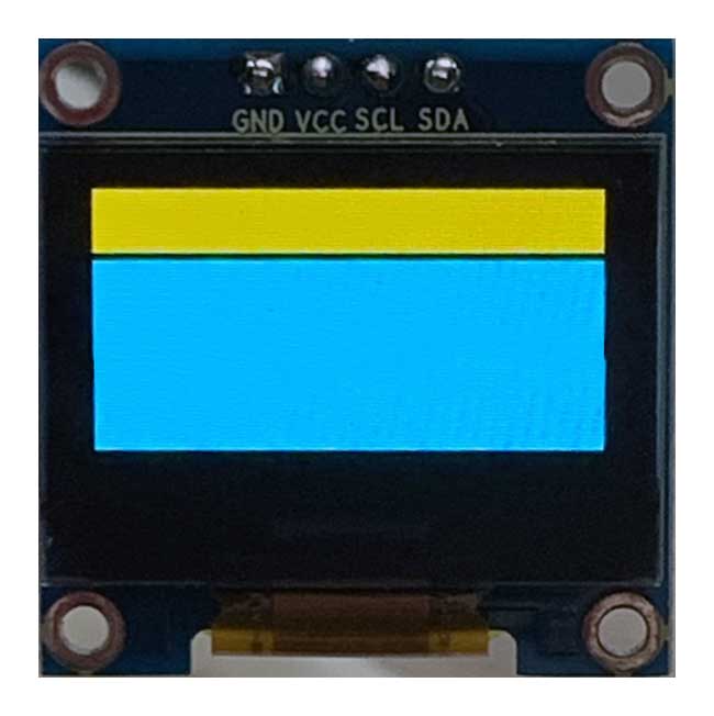
Regarding the colors the most typical is to find single color screens however, there are two colors for example blue and yellow. These are precisely the ones I have.
Display of graphs on OLED screen
I am going to explain above how the OLED screen works when displaying data. If you want to go more in depth on this topic I recommend you to refer to the datasheet.
To display the data on the screen, the SSD1306 controller has a graphic RAM called GDDRAM (Graphic Display Data RAM) that occupies 1 KB.
This is equivalent to 1,024 bytes or 8,192 bits that are distributed on the screen in a matrix of rows (pages) and columns (segments). In total there are 8 pages (rows) and each page has 128 segments (columns) which, in turn, each segment stores 1 byte.
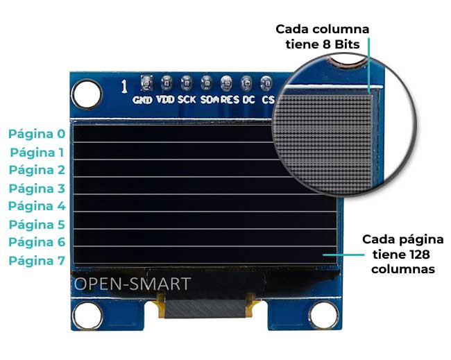
This layout is valid for 128 x 64 displays. 128 x 32 OLED displays only show 4 pages which is equivalent to half a KB of the SSD1306's RAM.
Therefore, we have a matrix of 128 columns and 64 rows. You can see all this in the programming where I will show you how to loop through the whole screen with two for loops.
Each bit represents a pixel on the OLED screen and through programming, you can turn it on or off to display any information.
But don't panic, we won't have to work at the bit level. That's taken care of by the Arduino and ESP8266 libraries. But before we dive into the programming, let's take a look at the pinning of the OLED displays.
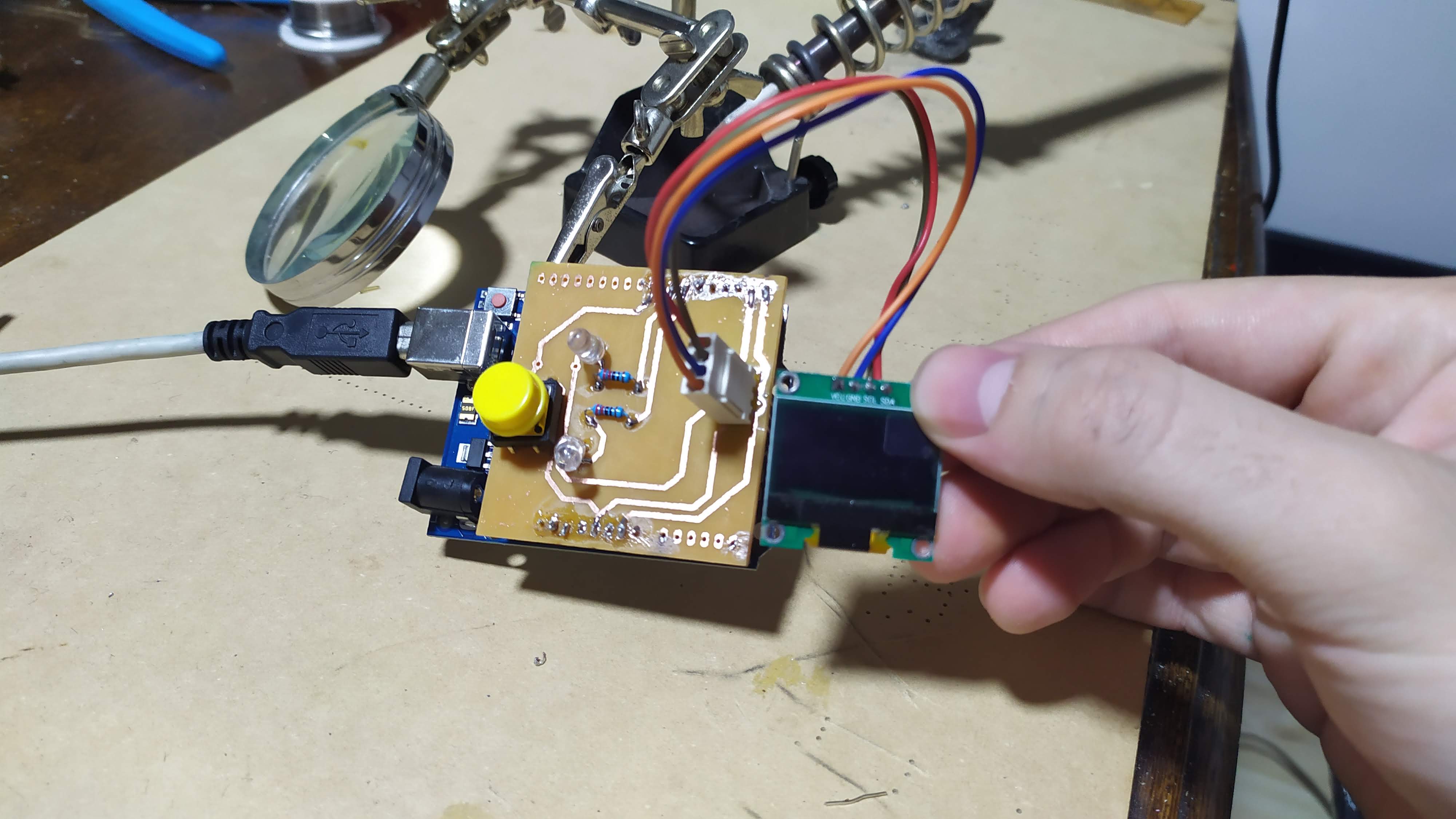
ineado OLED display module with Arduino and ESP8266
The OLED display that I am going to show below is a display that uses the I2C interface. In this type of displays you are going to find 4 pins.
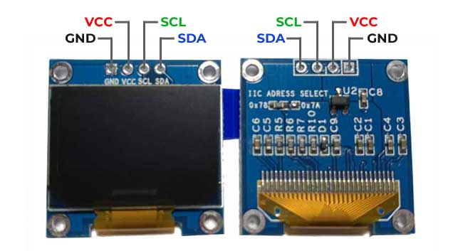
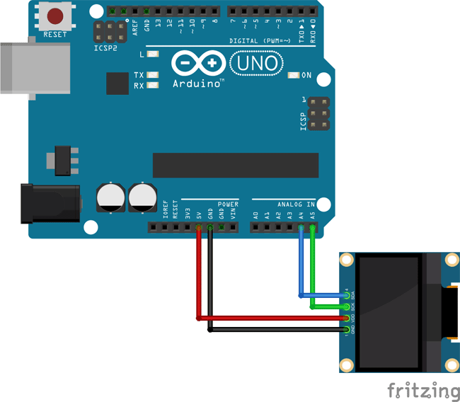
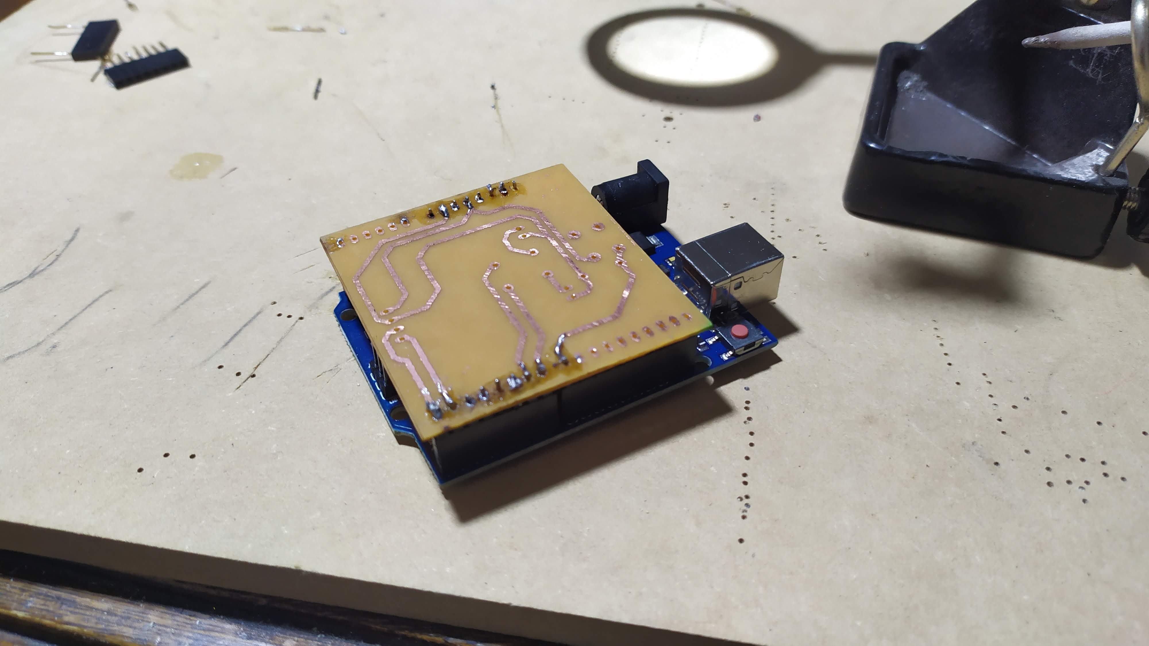
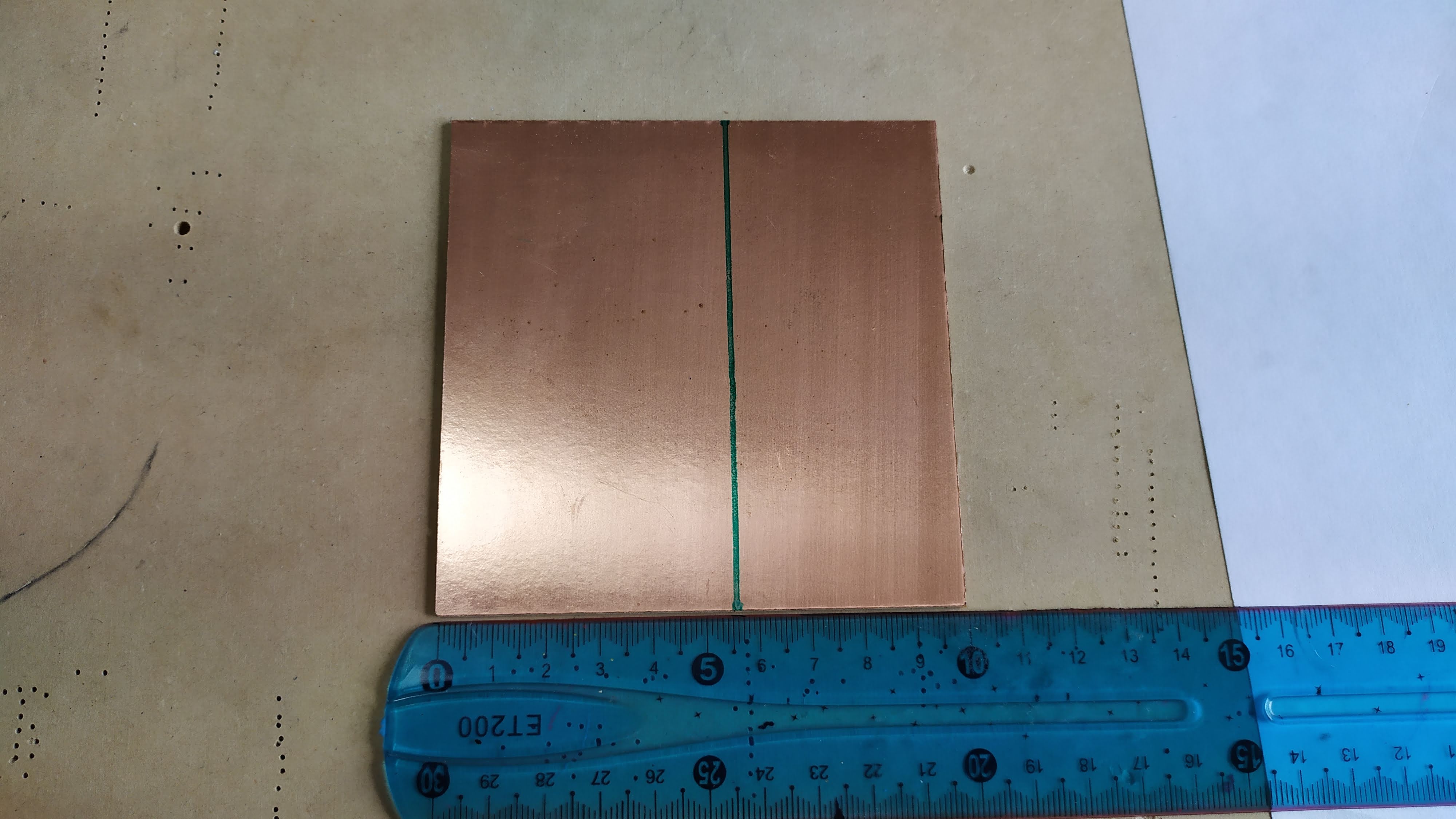
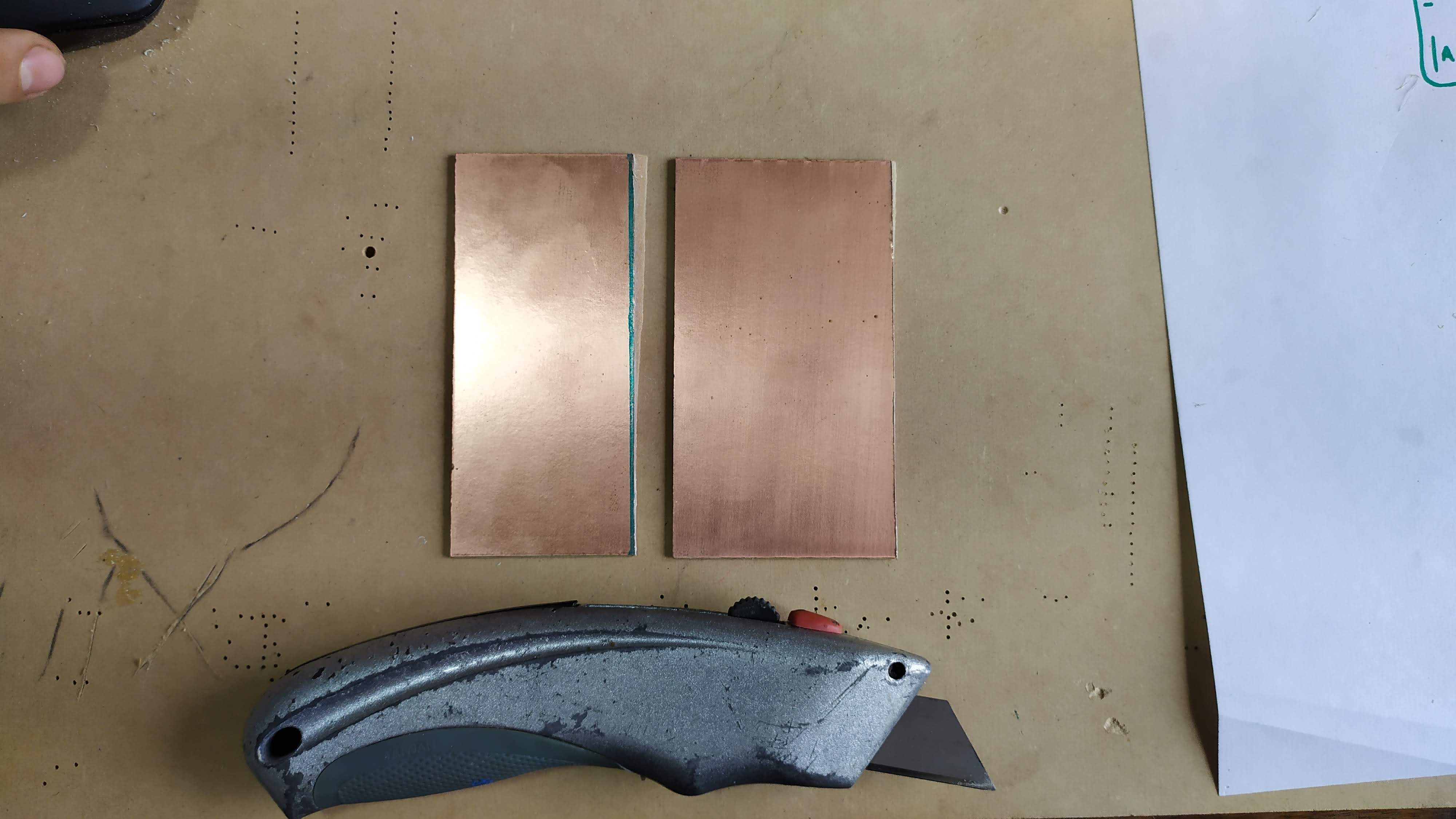
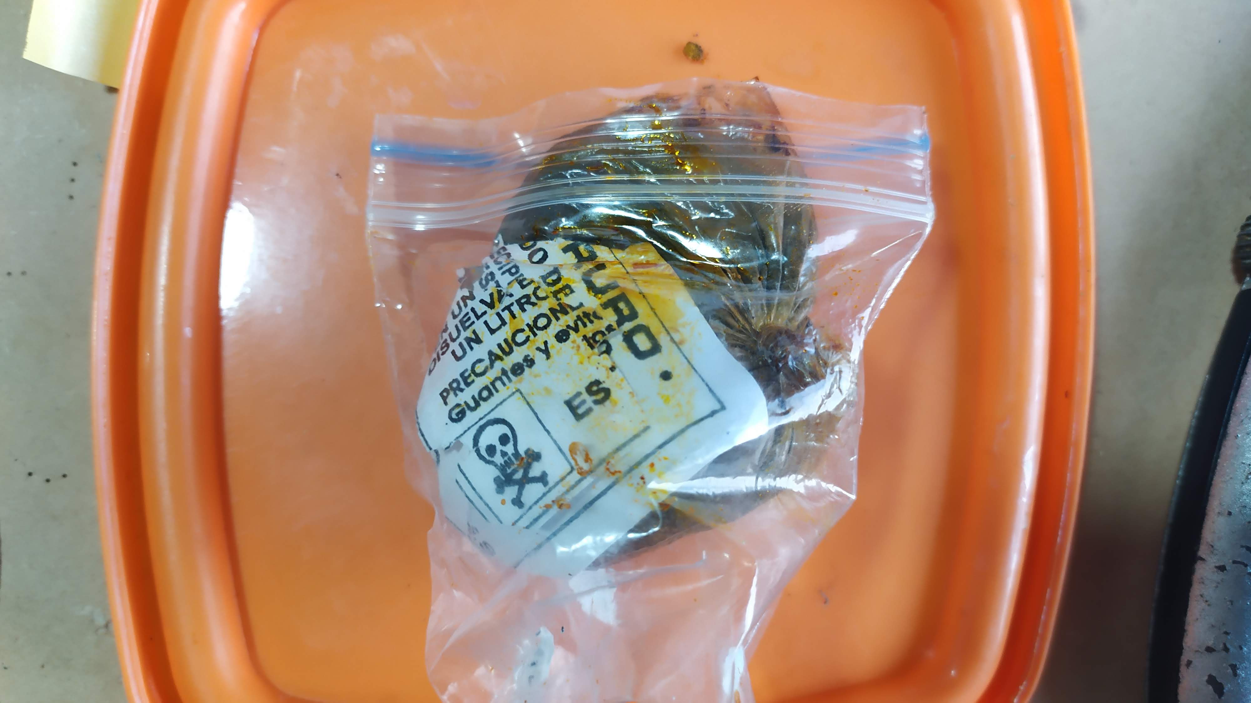
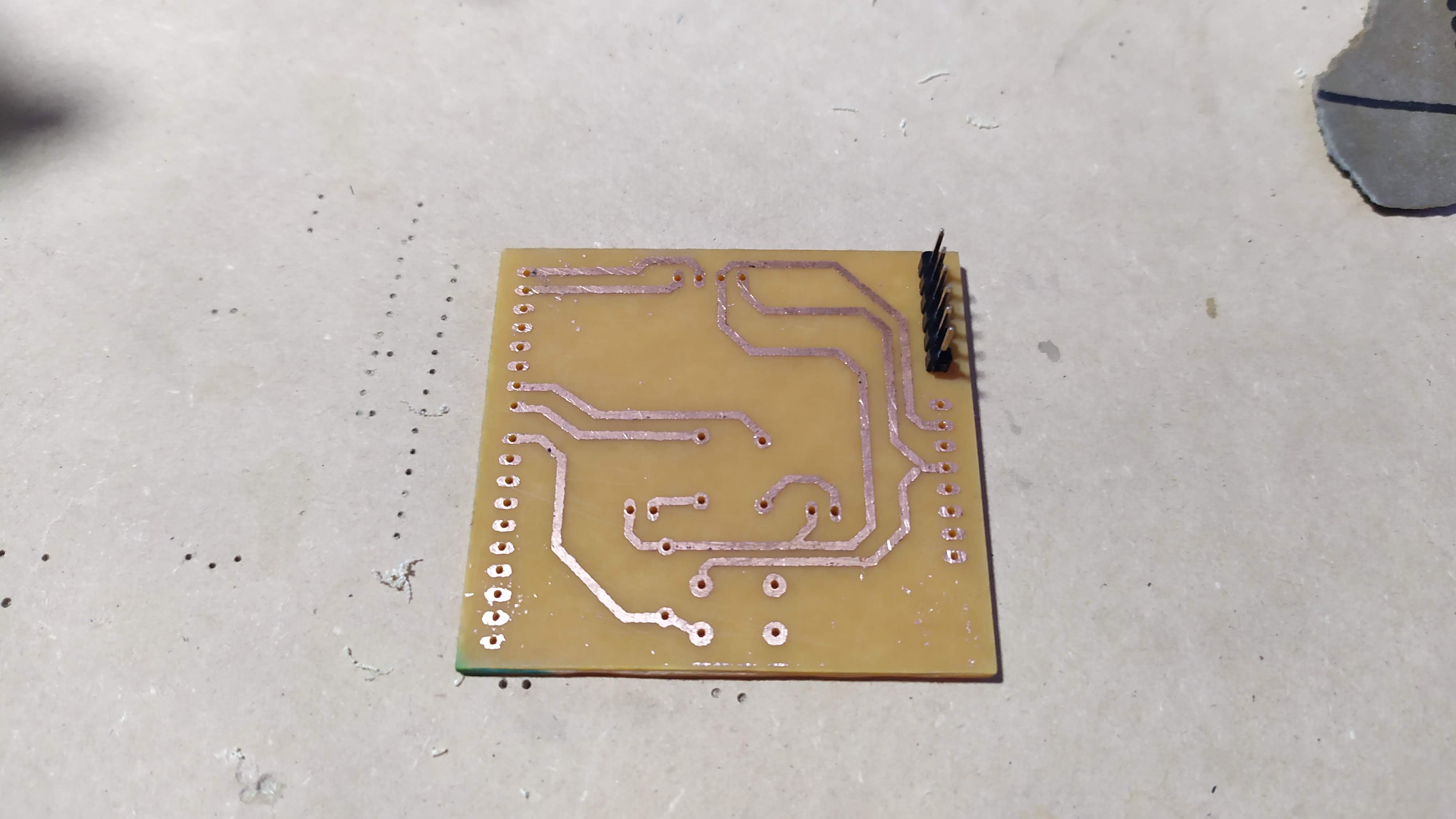
Plate manufacturing
cut the PBC with a scalpel and grind the resulting edges.
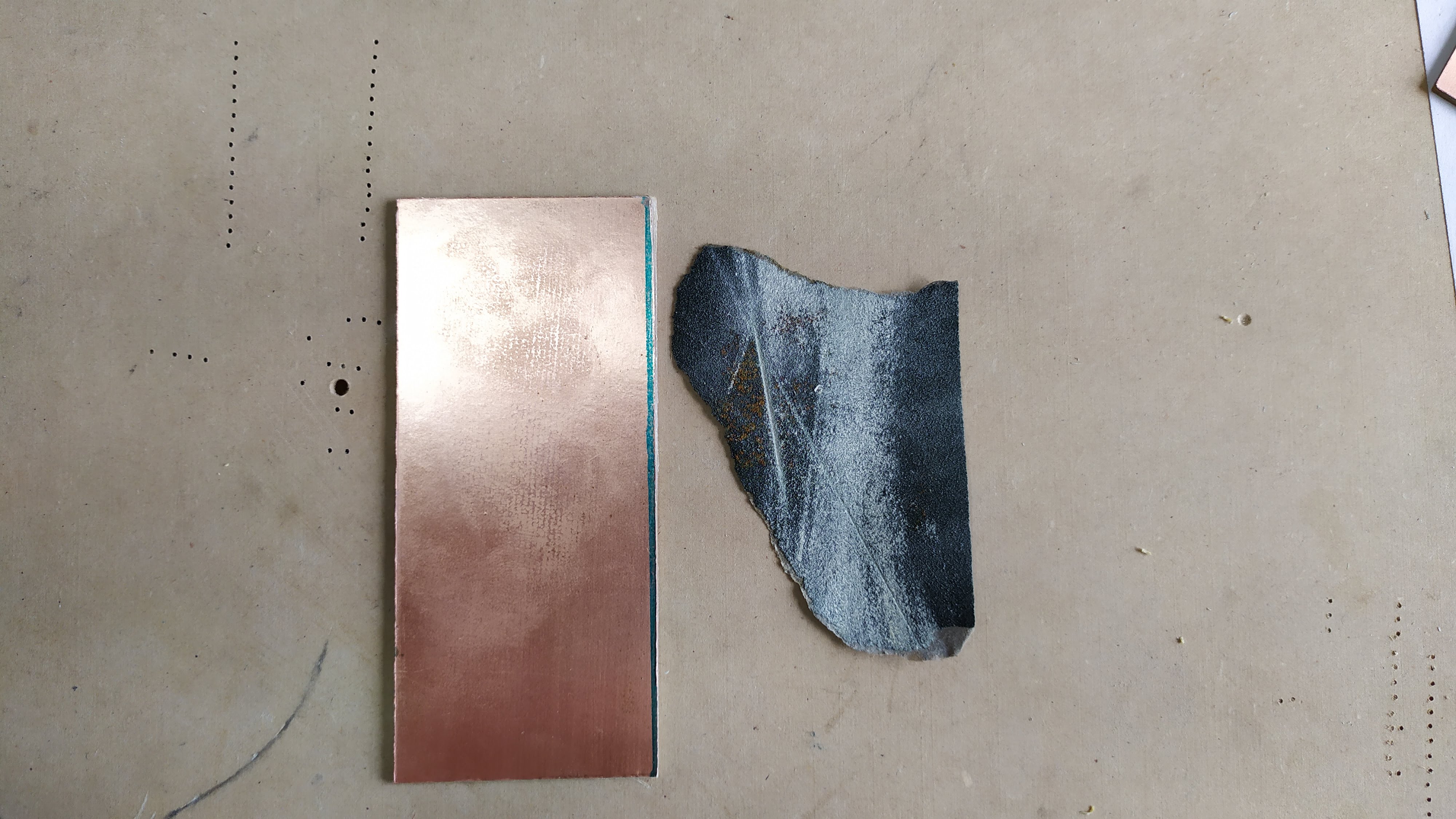
Print the electronic lines on transfer paper
place the transfer paper on the PCB board and roll it up with a sheet of paper to prevent it from moving, then iron it with heat for approximately five minutes, applying pressure.
After five minutes soak the plate in water and then peel off the excess paper and soak in ferrous acid for 15 minutes and stir constantly to remove excess copper, the ink that was impregnated in transfer is responsible for protecting the copper lines.
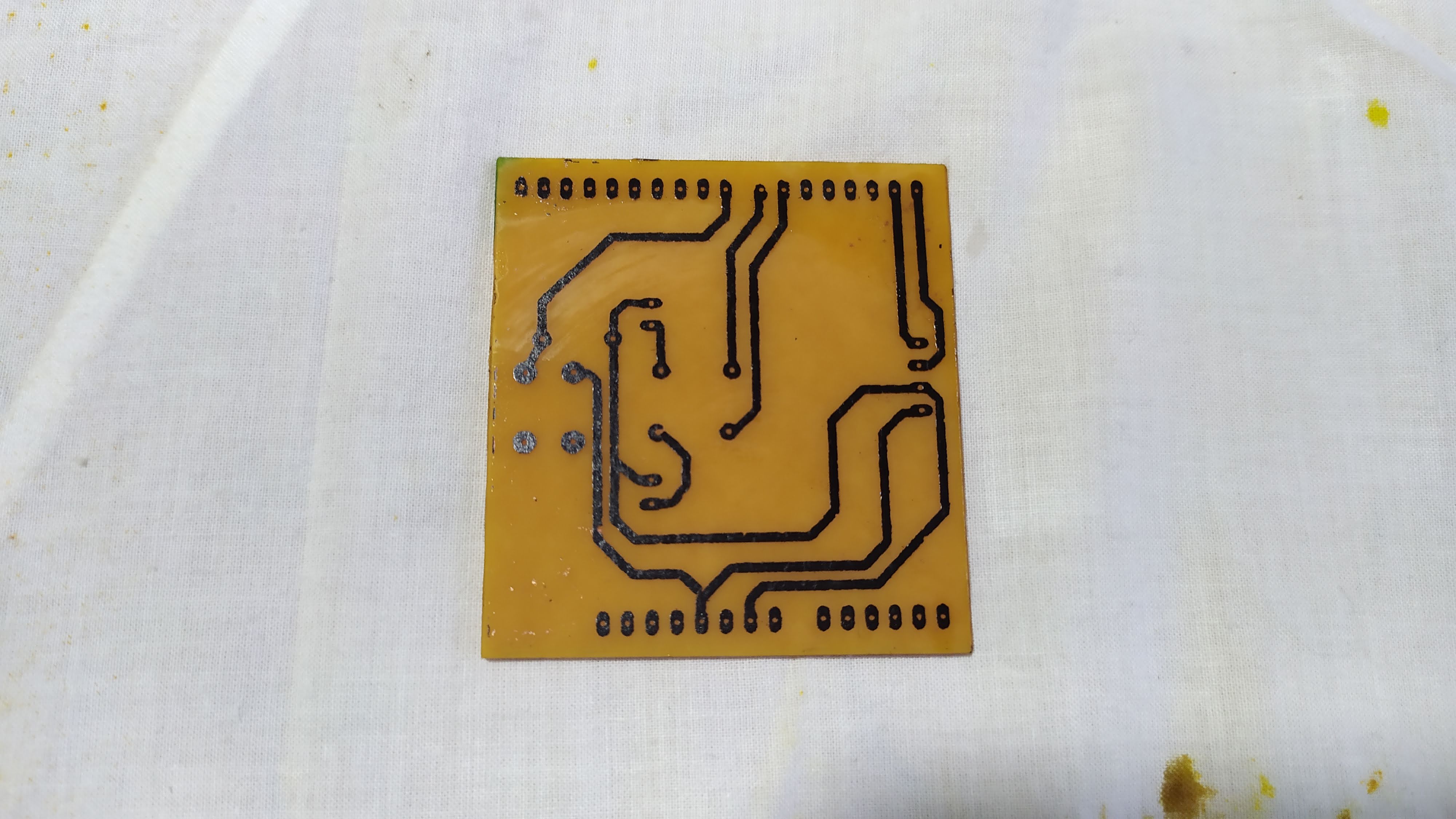
using a motortool, the holes are drilled to place the electronic components.
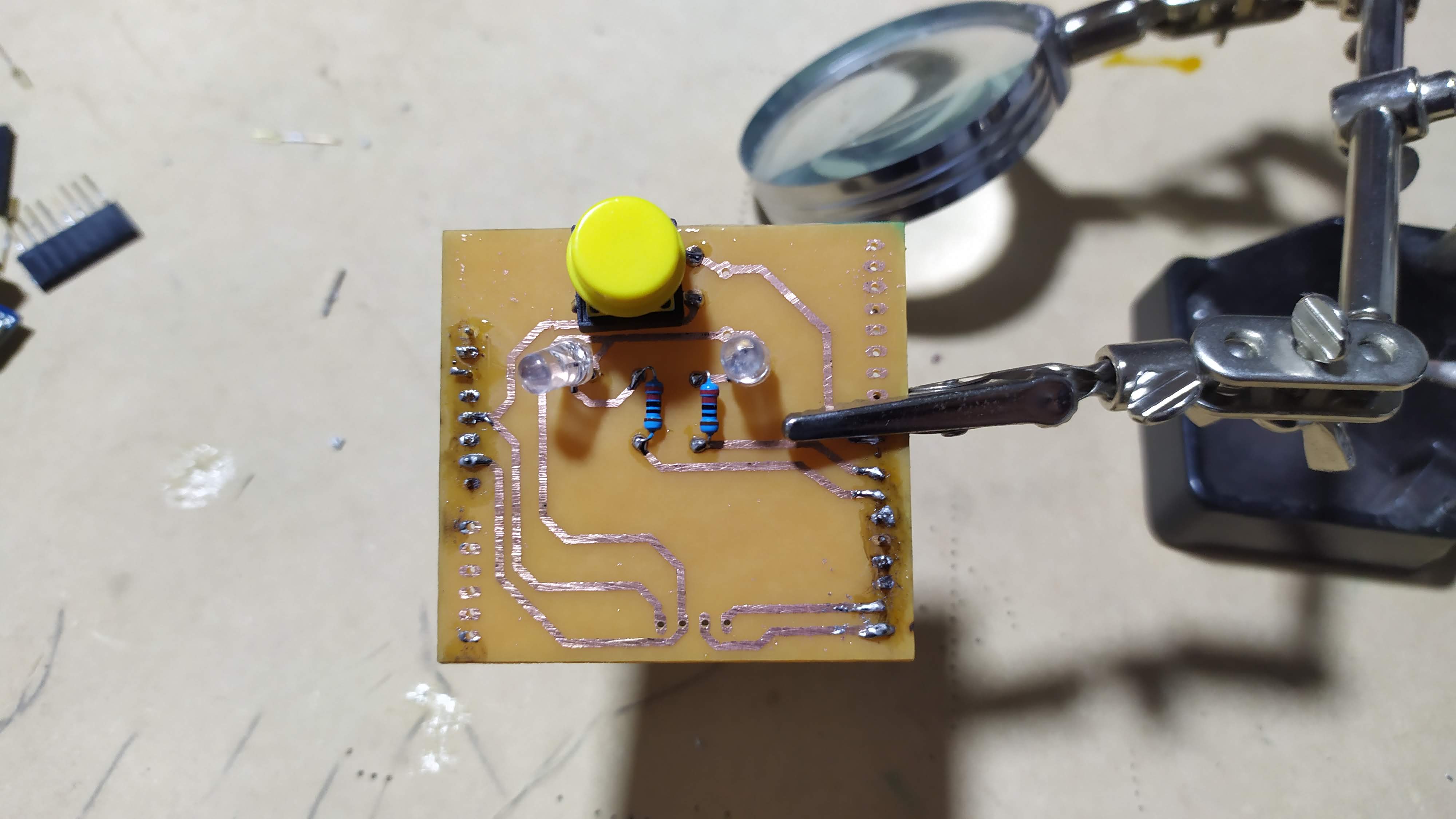
salting of electronic components and verification of electrical continuity in copper paths
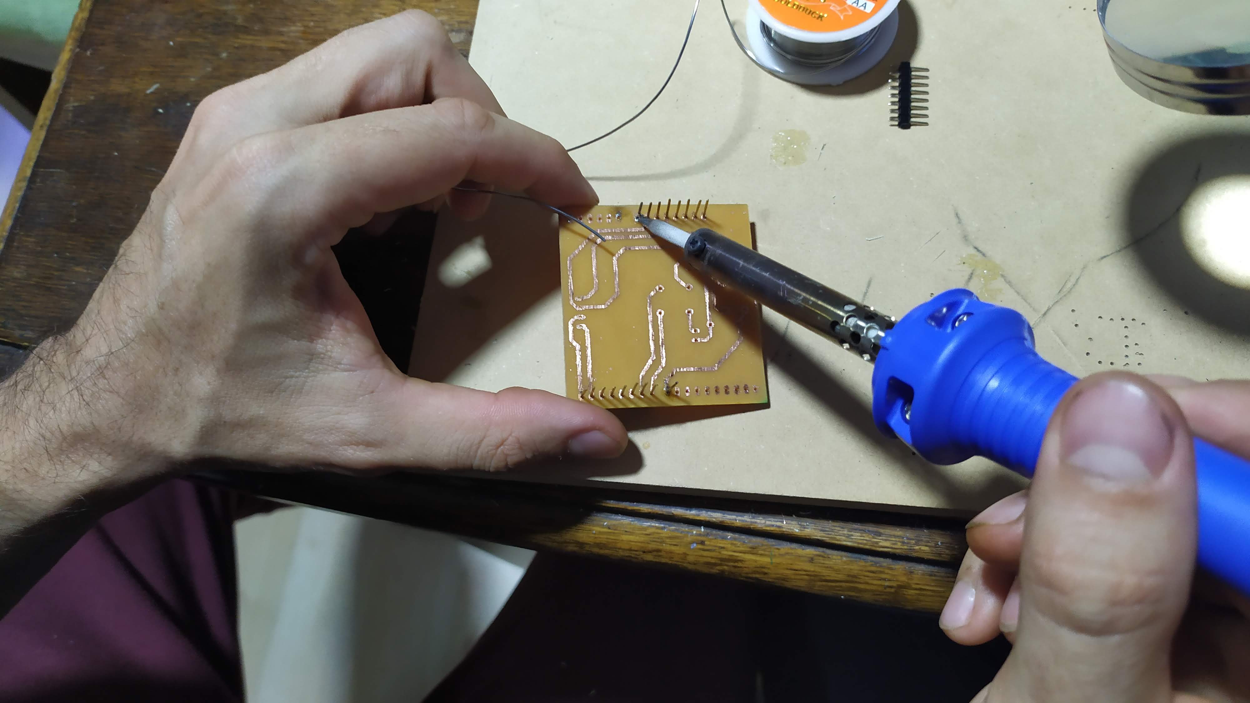
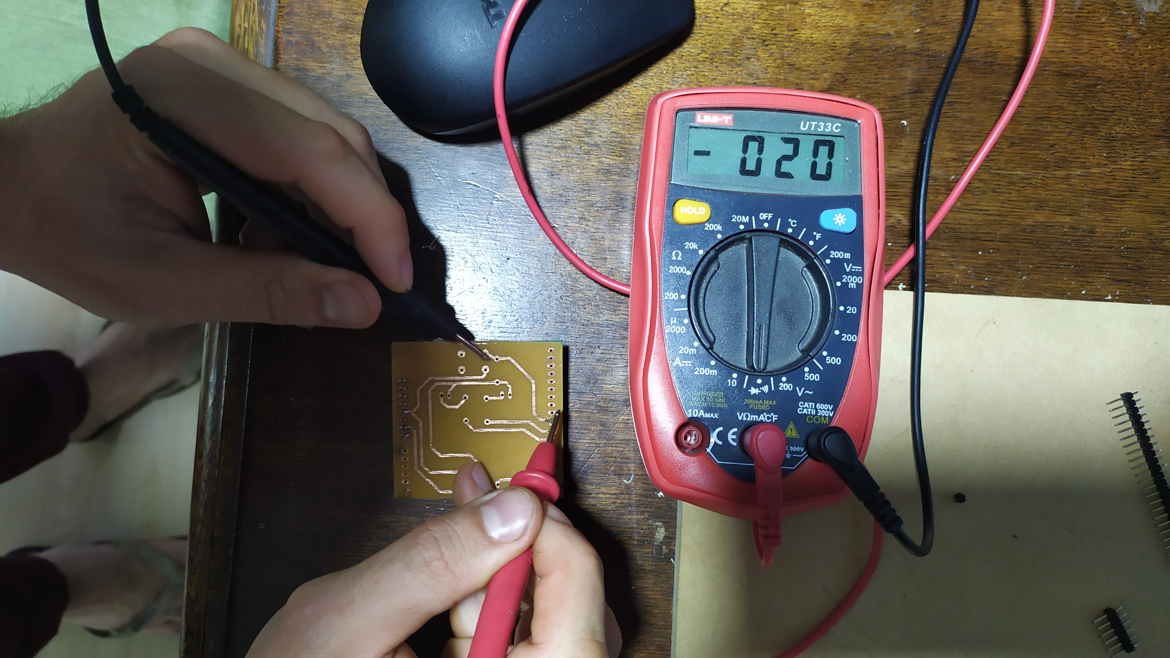
solder the other components