

Week 7 - Computer-controlled machining
Assignment
group assignment
      do your lab's safety training
      test runout, alignment, speeds, feeds, materials, and toolpaths for your machine
individual assignment
      make (design+mill+assemble) somethingbig (~meter-scale)
CNC training with Emmanuelle
I'm totally new to using a CNC machine. Below are the notes I made following training with Emanuelle in our lab.
Step 1 - Make your design in your CAD programme of choice
Step 2 - Use freecad to create toolpaths for you design
- export your cad design. use step file, not stl file
- import step file into freecad
- you should be able to select all faces. test that you can select and de-select individual faces and all should be selectable
- select 'path' from dropdown menu that says 'start'
- select path on main toolbar and select job. Press ok
- double click job on the left side panel
- go to setup tab
- The values on the axis tabs relate to the offset of the box around your model. Use 'extend model's bound box' unless you know reason to use one of the other options.
- The default of 1mm is fine for all the values
- go to tools tab and click add
- add a tool and fill in all the details using the tool you'll be using. details on both ooznest website and the small box that the bit comes in. use material carbide.
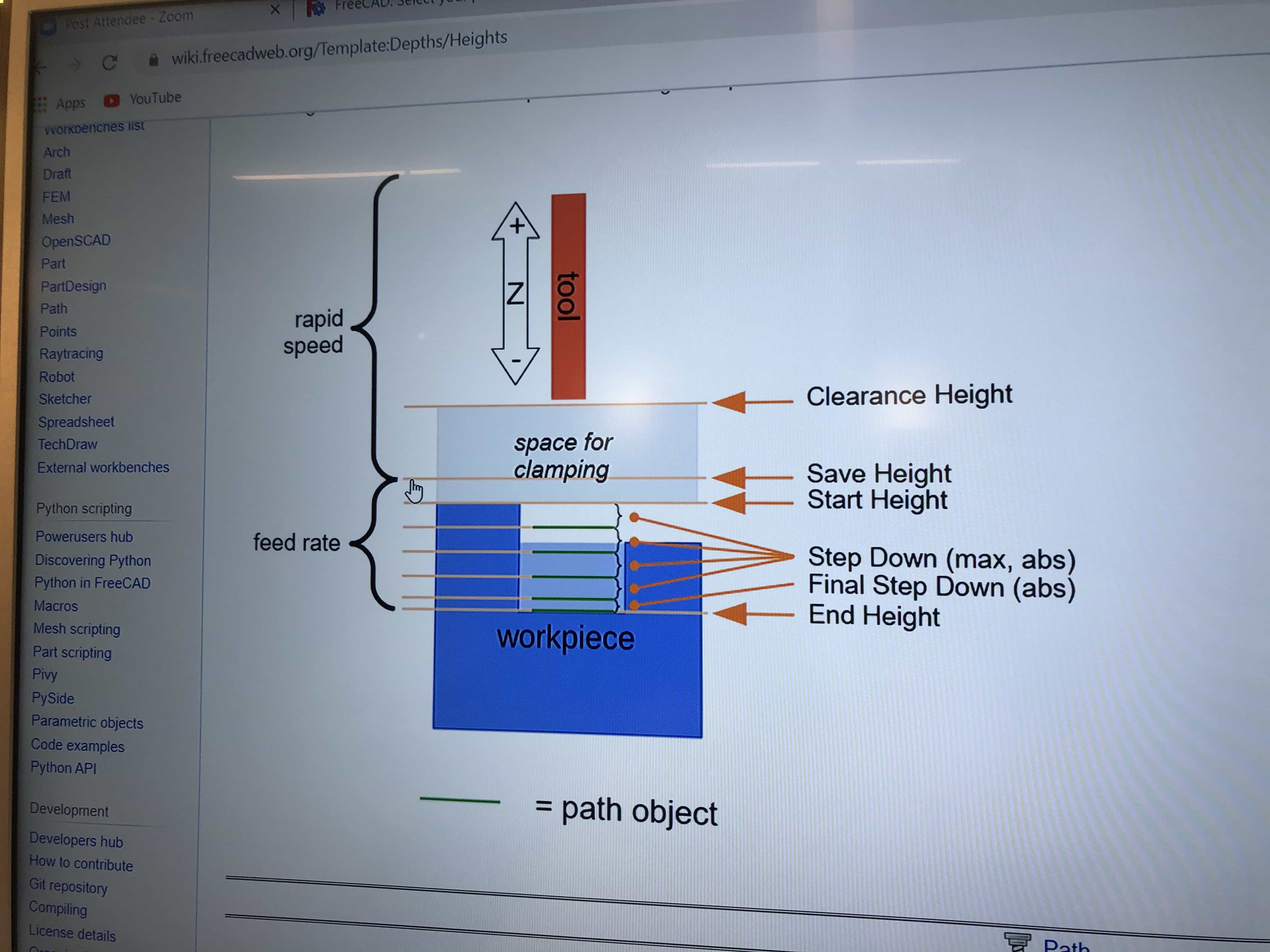
- Heights are important. Check the heights tab to see that everything is correct:
- Clearance height is the safe height where the bit can move free from obstacles such as clamps that hold down your material
- Safe height is the safe height where the bit can move free from obstruction from parts of your design, such as raised areas on your design
- Start height is where you will start cutting your material
- Step down is the height of each pass through the material. The first and final pass may be set at a different height
- End height is the height of your bed
- tick the checkbox for your tool and then click 'create tool controller'Clearance height is the
- feedrate is the speed at which the bit moves around the design. we can set this.
- spindle speed is the speed the bit rotates and it is set by the machine
- a long and large diameter toolbit is ideal
- if operations is greyed out, press space bar
- Click 'create contour' and select your tool
- stepdown should be approx diameter of tool. bit smaller if you want to be safe. if you're cutting foam, it could probably be anything
- rapid motion is moving tool without cutting
- controlled motion is moving while cutting
- start depth is the depth where you start cutting
- clearance height is the safe height that misses any clamps or other objects that might be in the way
- path - path dressup - dogbone dressup (remember to do dogbones then tags)
- path - path dressup - tag dressup
- export file from operations.
- processor - select grbl_post
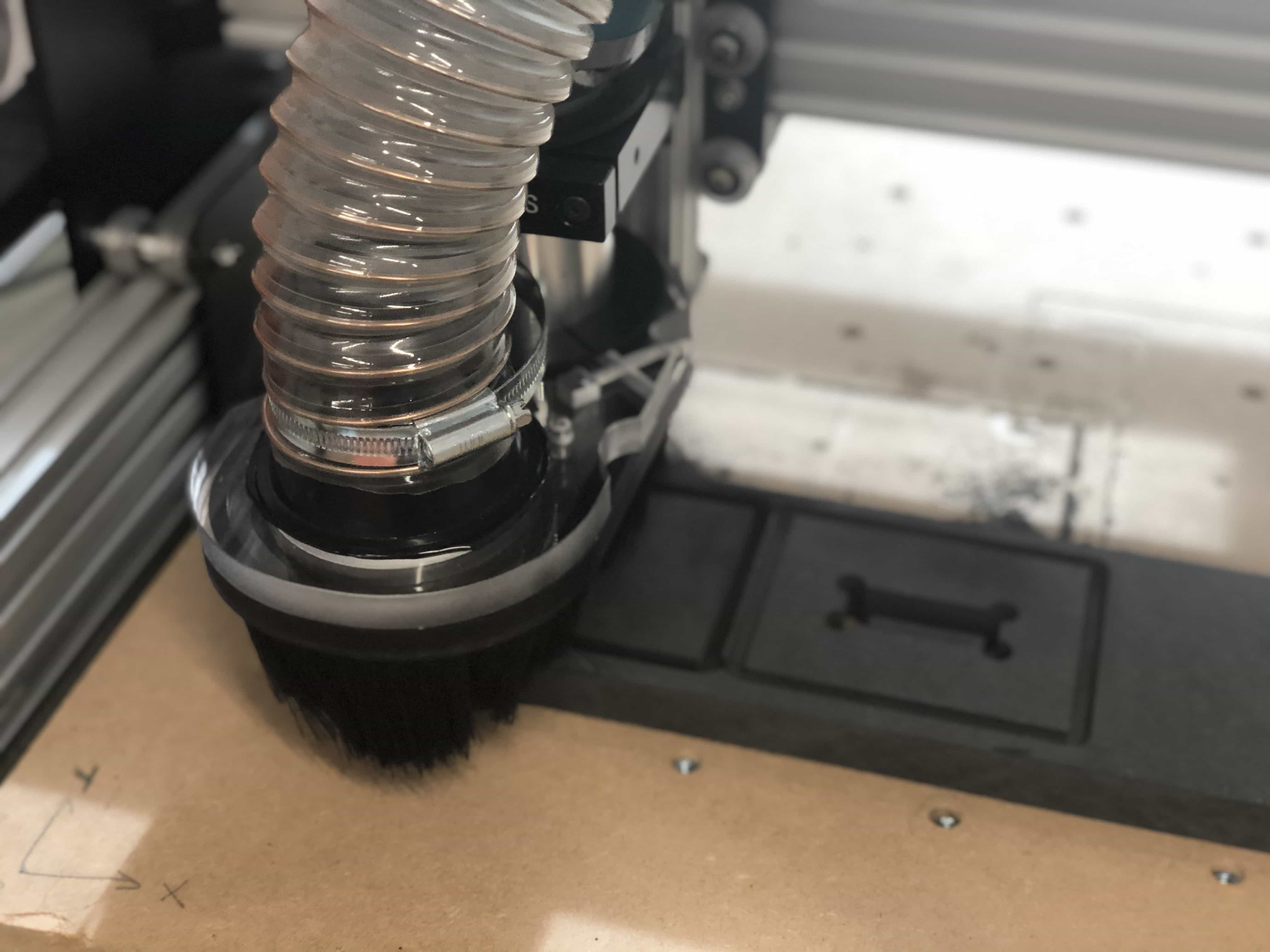
Step 3 - Use Workbee software to run the CNC machine
- go to workbee.local/
- changing the bit:
- turn both things off
- use the 24mm spanner from the mdx540
- push button and then loosen bolt with spanner
- change bit, find suitably sized collar, screw back together
- home x and y axis
- turn on router by turning on switch on the router while main power plug disconnected
- now shut the case and turn the main power on
- bring z axis down until it tickles the bed
- set Z axis to zero
- secure your piece with screws or clamps
- move the x and y axis to your desired origin
- set X and Y to zero
- use the lowest speed you can get away with. too fast and you'll get schorching
- close the doors and make sure there is nothing else inside the case. you can imagine leaving tools, clamps or other bits inside
- use tape to seal the doors
- do an air test
Lead-in feedrate
Surface speed
Cutting feedrate
Lead-out feedrate
Ramp feedrate
Plunge feedrate
Feed per revolution
Tool settings:
Pass settings:
Finish feedreate
Feed optimisation settings:
sunday 14th march
1 - kevin kennedy tutorials
Youtube tutorial with Kevin Kennedy
The basic workflow when using a CNC machine is:
CAD (Computer-aided design)
3 different cutting strategies
2D cuts - machine traces and object and cuts it out. eg letters and basic shapes
2d cuts - machine uses all 3 axis at the same time. more complex shapes with smooth gradient edges
2.5D - machine uses 3 axis but never moves z axis at teh same time as x or y. it means the depth is staggered like a staircase
CAM (Computer-aided manufacturing)
Step 1 - enter the dimensions for your material
Step 2 - choose your cutting tool. make sure its smaller than the objects you want to cut
Step 3 - define speeds.
cutting speed = how fast the cutting tool moves in relation to material
feed rate = distance the tool travels during 1 revolution of the tool
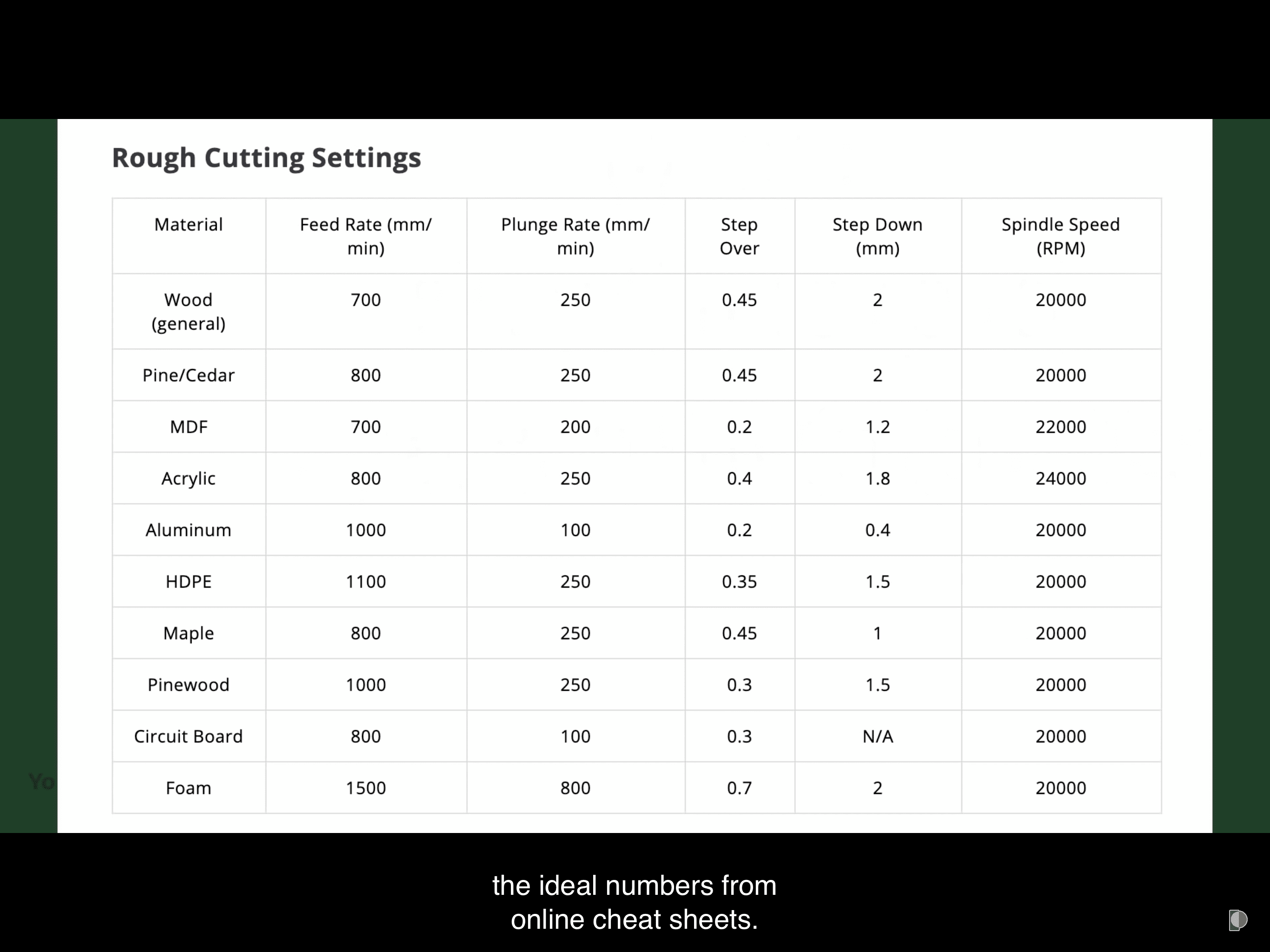
Here is a cheat sheet with some speed and feed rates:

Create toolpath - this is where we tell the software what path to follow
Great advantage of CAM software is that we can simulate the toolpath before we print
CNC
Most CNC machines use Gcode (Geometric-code). This tells the machine where to travel to.
For our machine, we will use the local network to share the gcode with the CNC
Screw or clamp the material down
Attach the same size bit you used in your CAM
Turn on the router
Upload and start to run your gcode
Most errors are caused by including extra instructions you didn't want
This was a lot to take on and I felt like I'd benefit from going over everything a second time. I turned to my trusty youtube tutor Kevin Kennedy who had 2 tutorials for using Fusion 360 with CAM. Below are my notes for the 3 steps of CAM. So this is effectively a breakdown of Step 2 above:
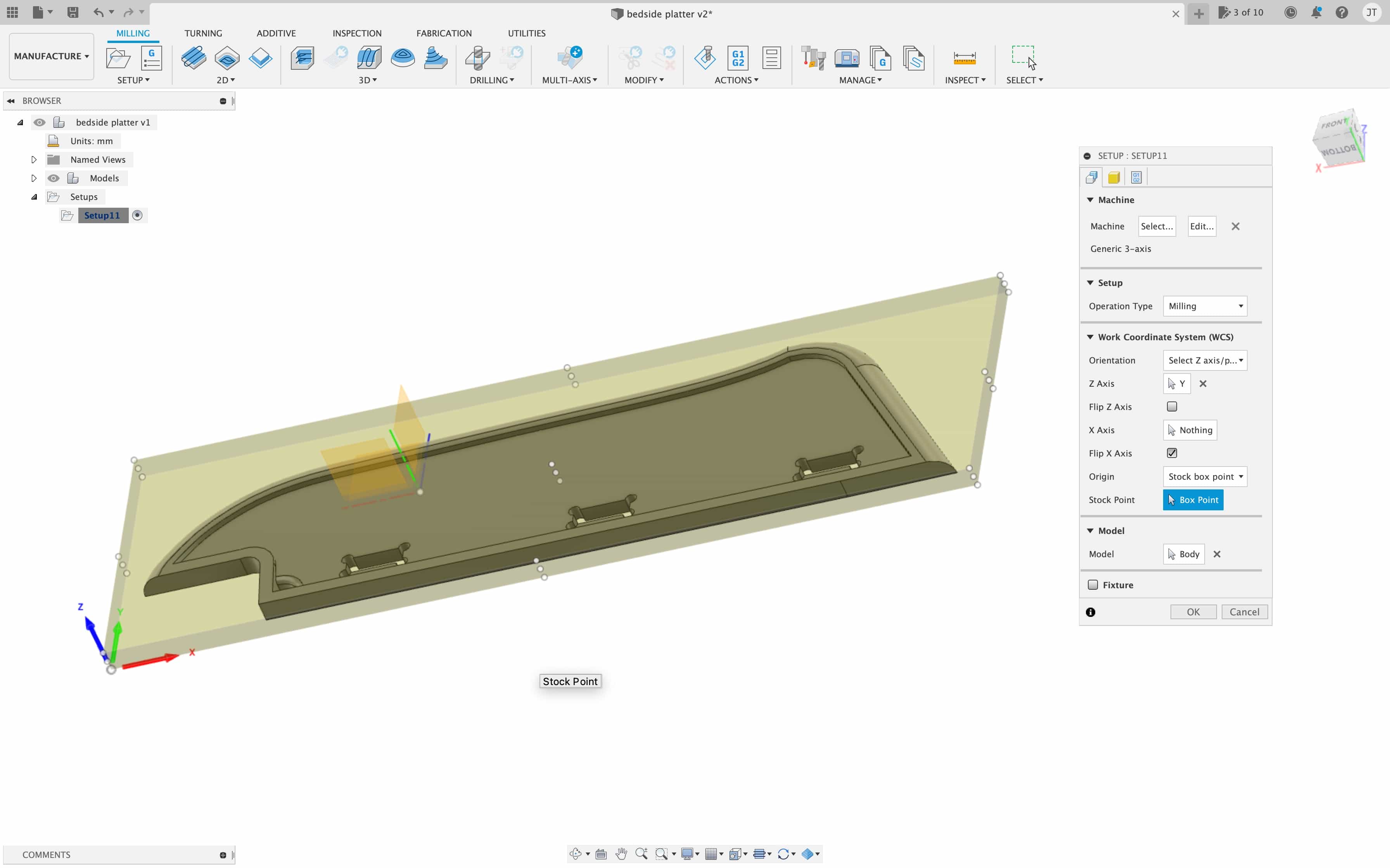
Step 1 - Setup your machine
- Click 'setup' icon in the toolbar
- Choose your machine. I will choose Autodesk generic 3 axis
- Choose your operation type. I will leave it as 'milling'.
- Choose your orientation. I will leave as default of 'model orientation' as my model is in the correct position.
- Set your origin. I will use Stock box point and set the point to the bottom left corner
- Select body. This one done automatically by Fusion 360 as we have only one body to choose from.
Setup your material
- Now click on 'stock' tab so we can set up our material.
- Select mode. If you have a piece of material in hand, put in the exact dimensions with fixed box size.
- I shall use the 'relative size box' and set an offset to give me space for clamping it down to the bed.
- If your material is the same height as your design, you can set the top offset to 0.
- You can use the 'round' value to help avoid random dimensions
Setup your toolpaths
- Select the appropriate type of toolpath. I will use 2D contour for my first cuts
- Select the geometry you wish to cut. If you wish to cut all the way through your material, you'll need to select the bottom edge.
- On the toolpath setup menu, if working with wood, turn off coolant
- Tabs are important. They allow you to cut out almost all the material, while leaving small tabs that keep the material in place. They can be removed manually with a wood tool.
- Cutting settings are super important. This table is a great startpoint for guidelines on speed. I'm using 18mm plywood and just to be cautious, I'm going to use 50% of these recommended settings for 'Wood(general)'.
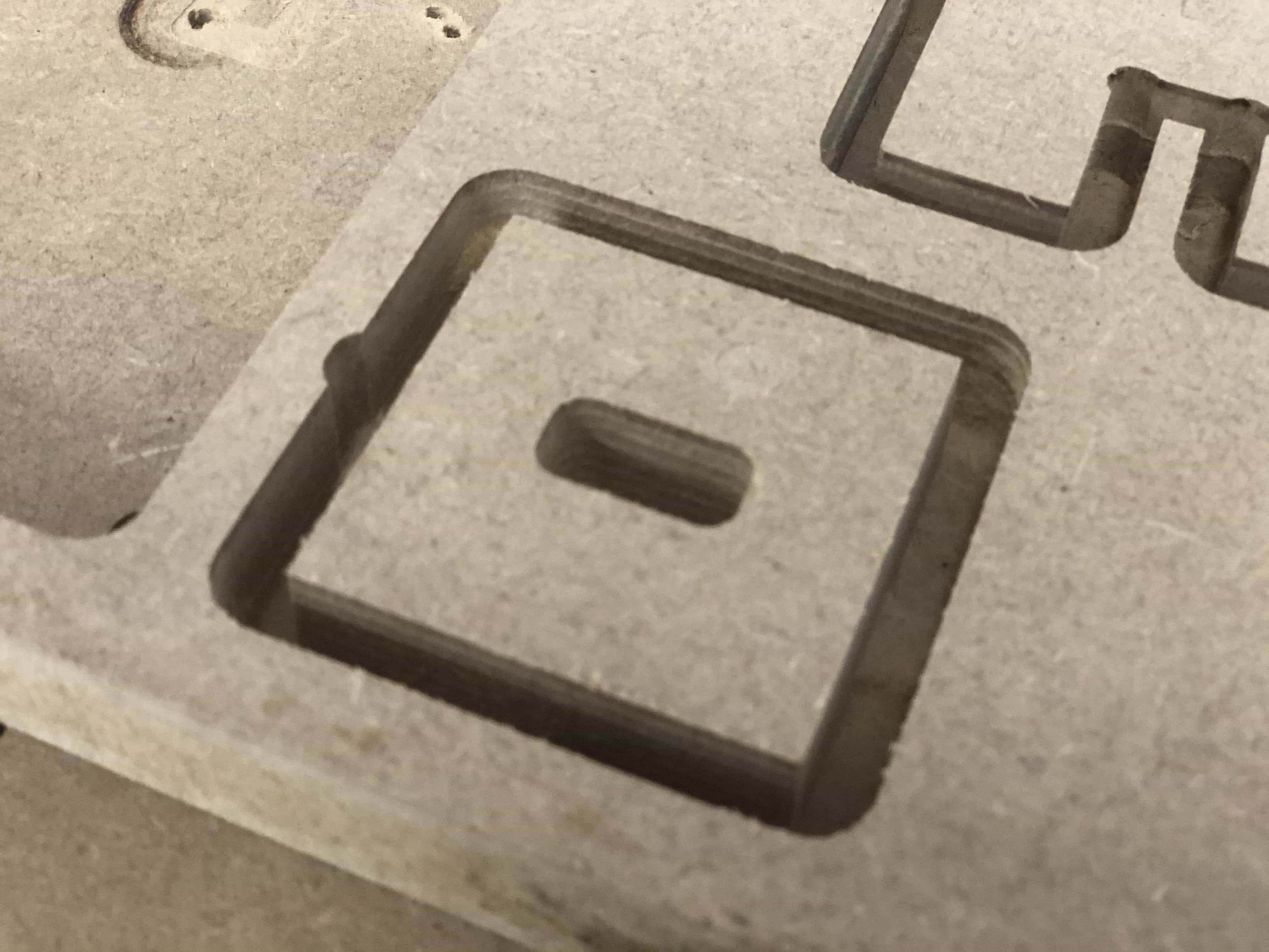
First cuts
Using the instructions above, I setup to make my first cut. I nearly broke the mill bit with the cut below:
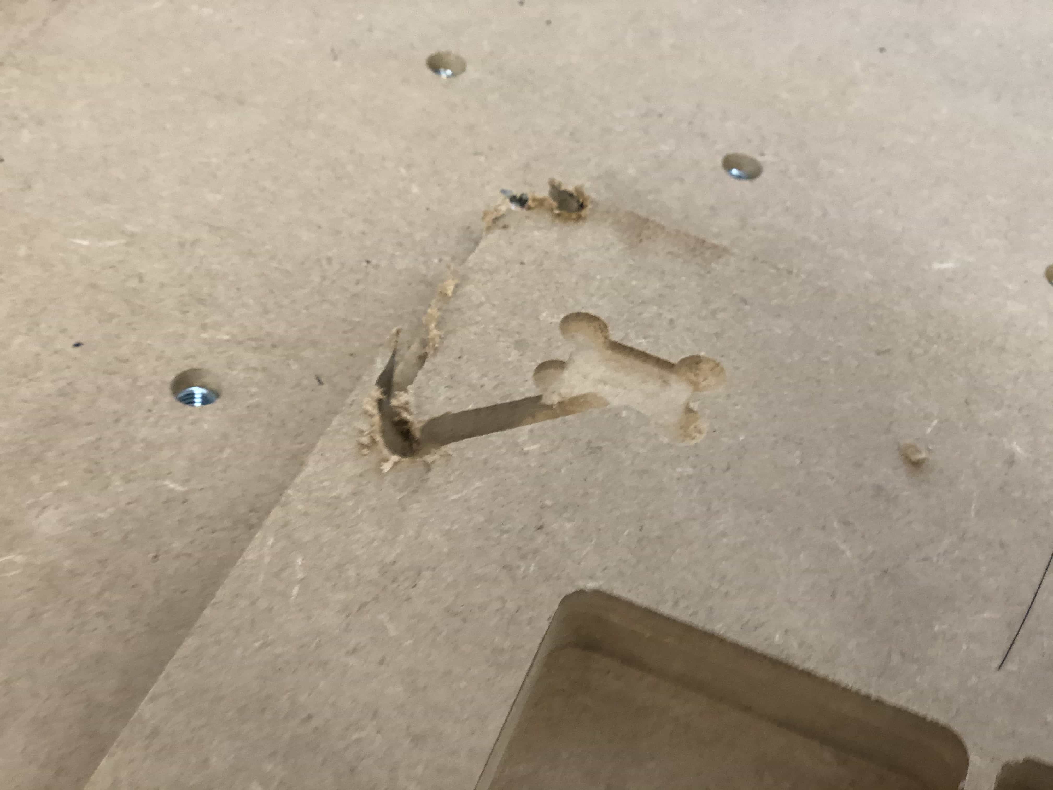
The mistake I made with this design above was that I had set the Z axis to the top of my material, but on my design the Z axis was set to be on the bed. I tried again and everything printed out OK:
Then we tried using some different material. This cut below is using velcromat.
Make something big
I shall be making a bedside shelf that runs along the length of my bed and most importantly, fills the gap you see in picture below:
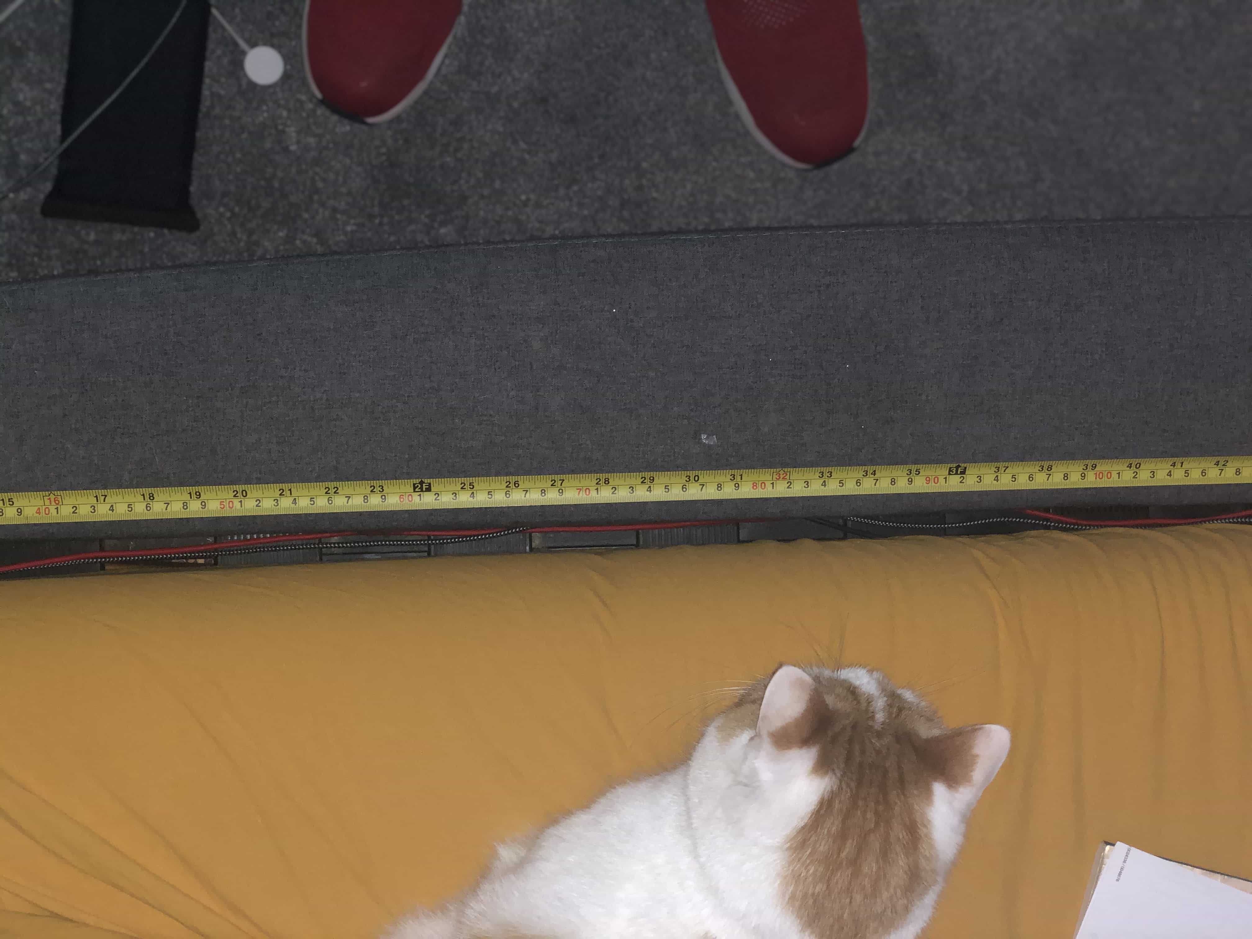
I like to fall asleep listening to stories or podcasts and if I wake in the night, I like to do the same to go back to sleep. I need 2 items at my bedside which are my phone and wireless earphones. About 50% of nights I will lose one of those 2 items down this gap between bed and mattress. So I plan to make a shelf that will wedge itself inside that gap and give me a useful shelf with cut-outs for phone and airpods.
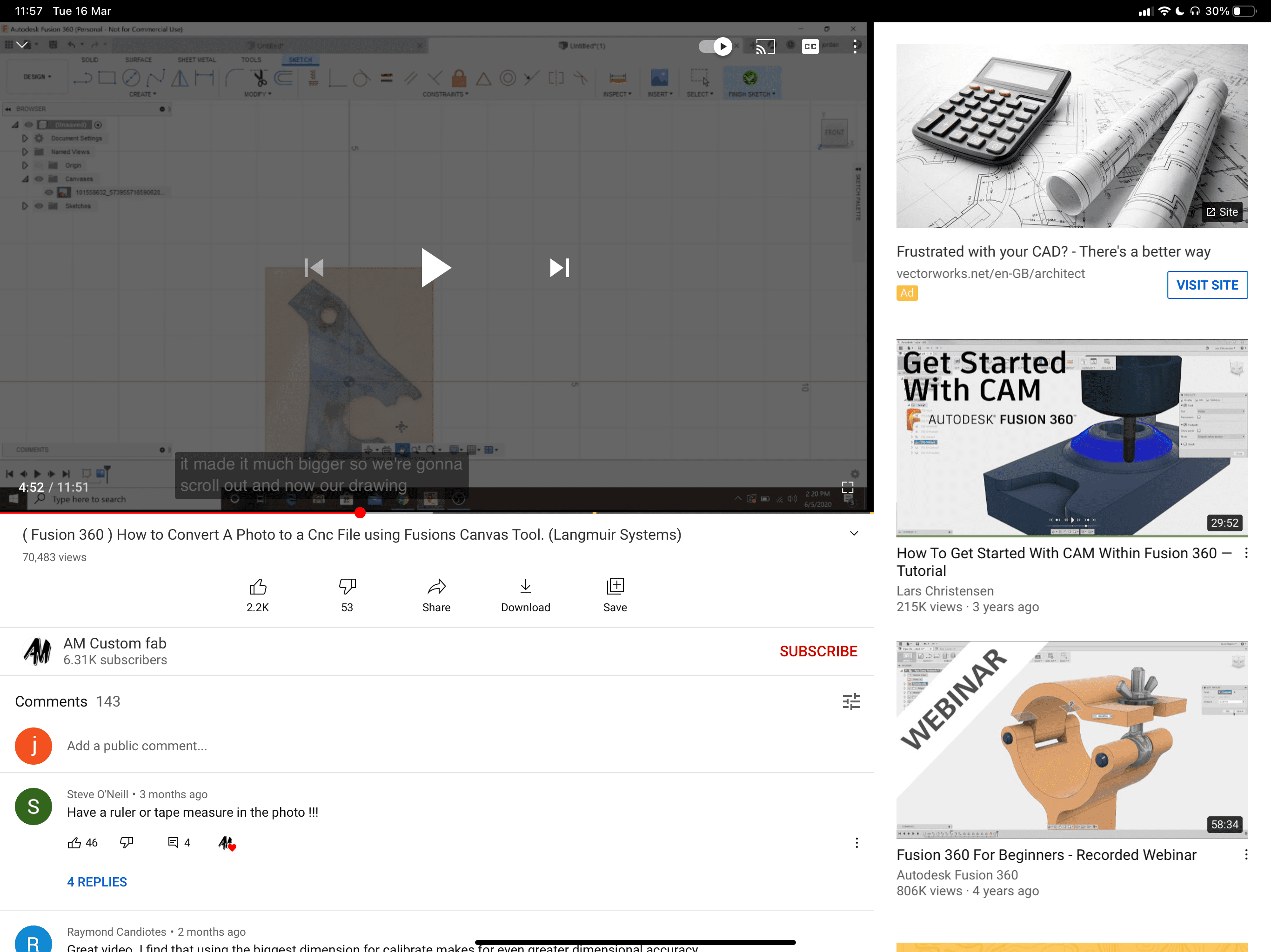
Using Fusion 360 with a photo
I watched the tutorial below which teaches how to import a photo to Fusion 360 and calibrate the size. I included a tape measure in my photo which was ideal for the calibration.
To create a design from a photo, do the following:
- Click 'Insert' and select 'Canvas'
- Find your canvas in the browser on the left. Right click it and click 'calibrate'
- Select 2 points, where the distance between is known. The longer the distance, the more effective the calibration.
- Fill in the distance and click OK. Your image is now calibrated for size.
- Pick a suitable sketch tool. I shall use the spline tool because my item has a curved edge.
- After your sketch is complete, you can hide or delete the image canvas.
Here is my sketch created from the photo:
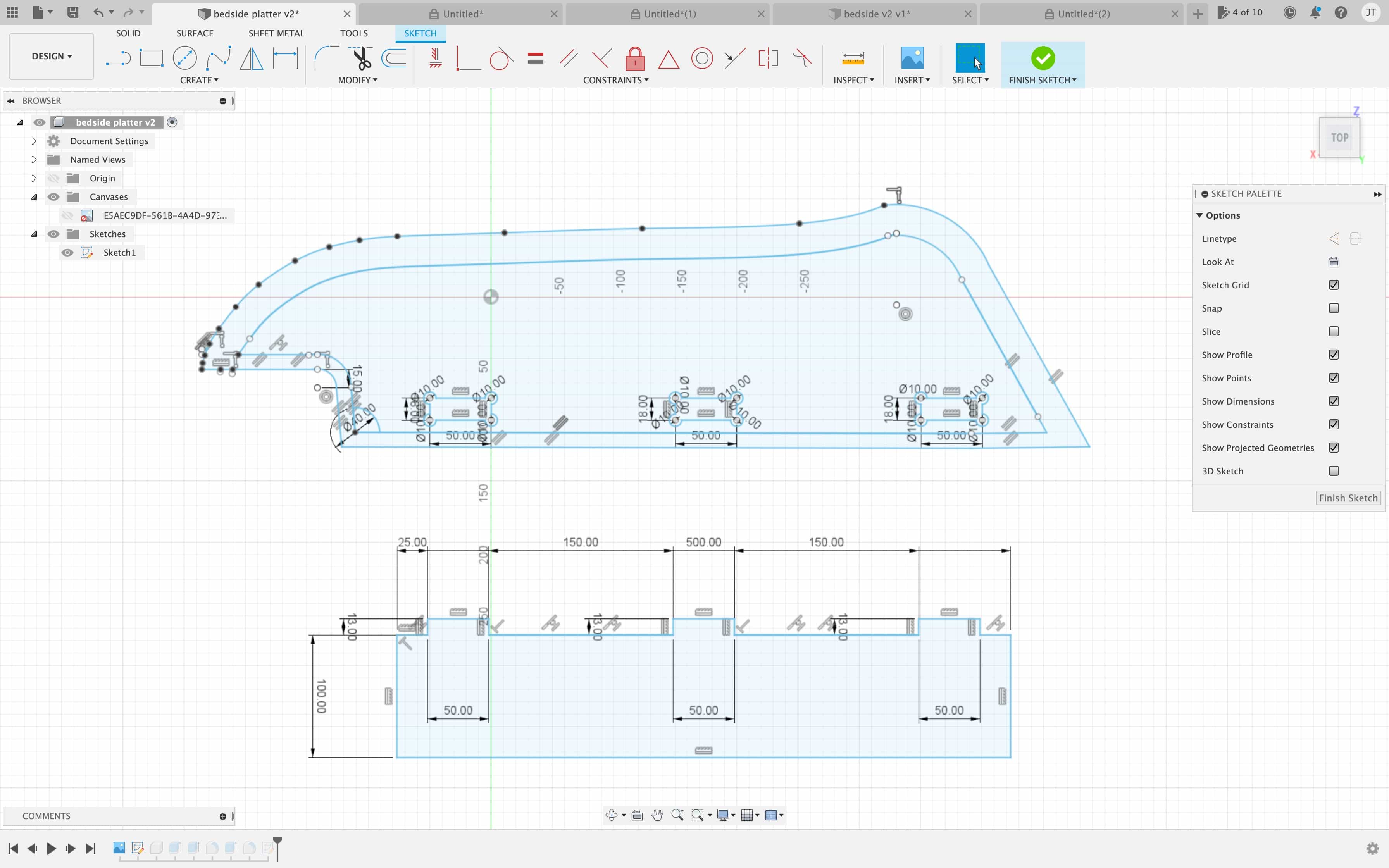
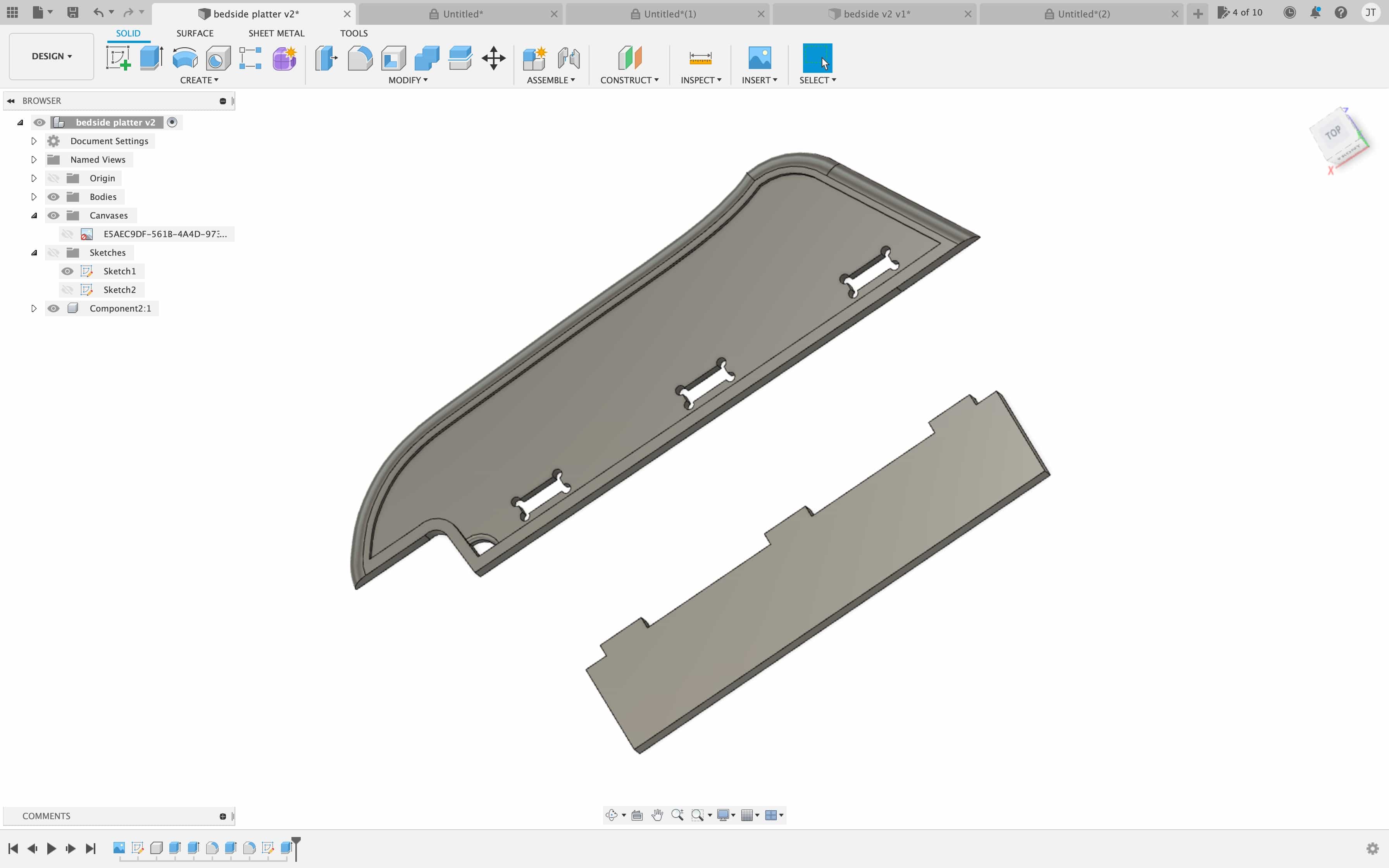
Here is the component created from the sketch:
Here is the design set up in CAM with material:
Material and tool
I am using a large sheet of plywood with thickness 18mm. We have several sheets of this plywood that were intended to be used as doors. Then the design of cupboard was changed and we were given the doors to use for projects. The dimensions of each sheet is 700mm x 420mm. The mill bit I am using is 6.35mm thickness. It is this mill bit here, size 1/4 inch and type is stanard:
1/4 inch millbitTest run with small version
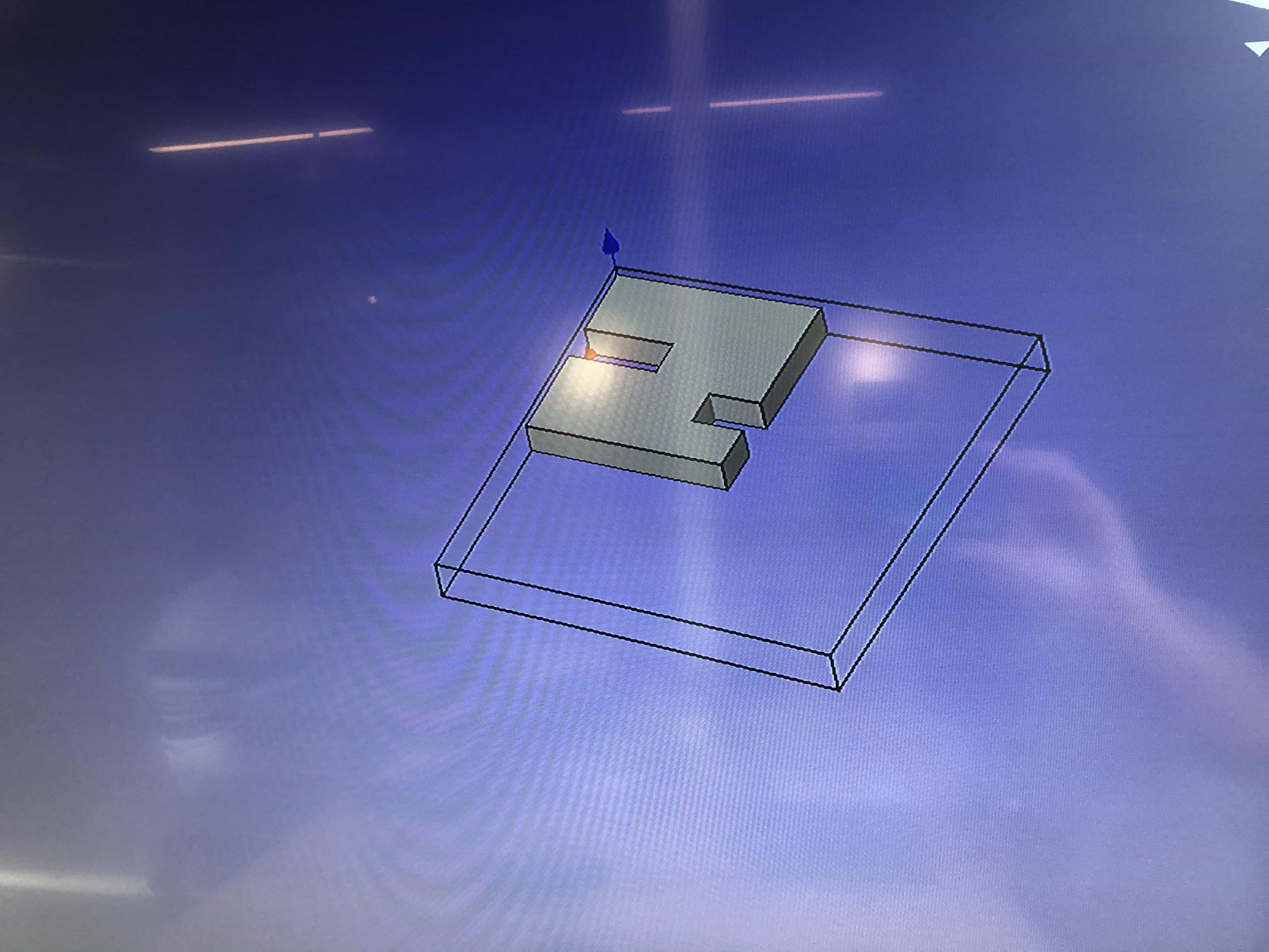
I used the scale tool to make a small version, just 10% of final size. My plan is to keep practising on this design until I can make it perfectly. Then I'll risk the big design.
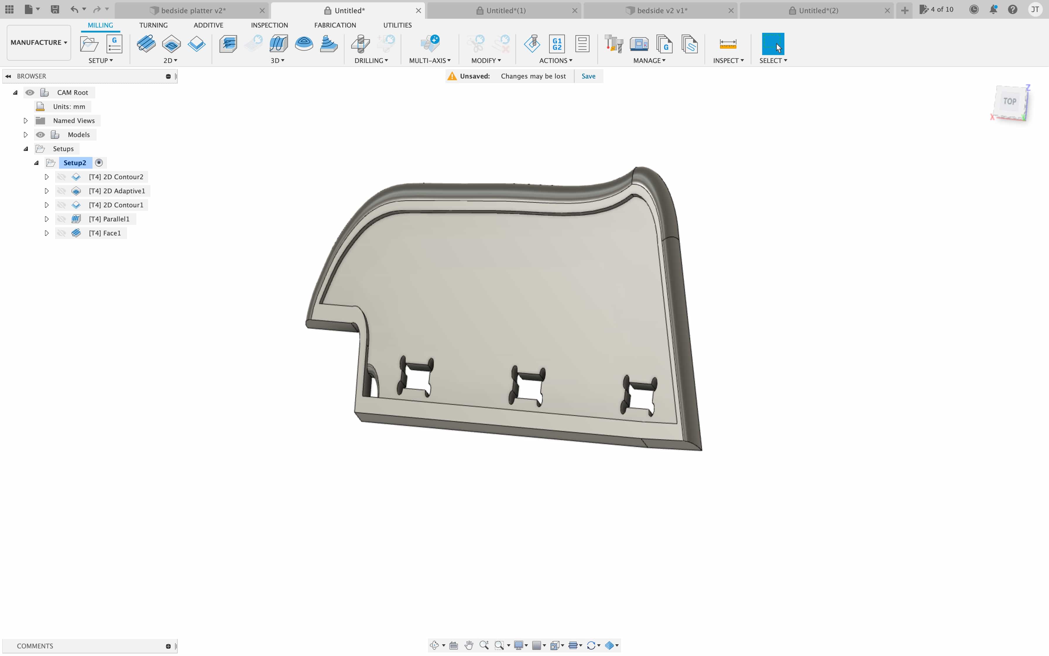
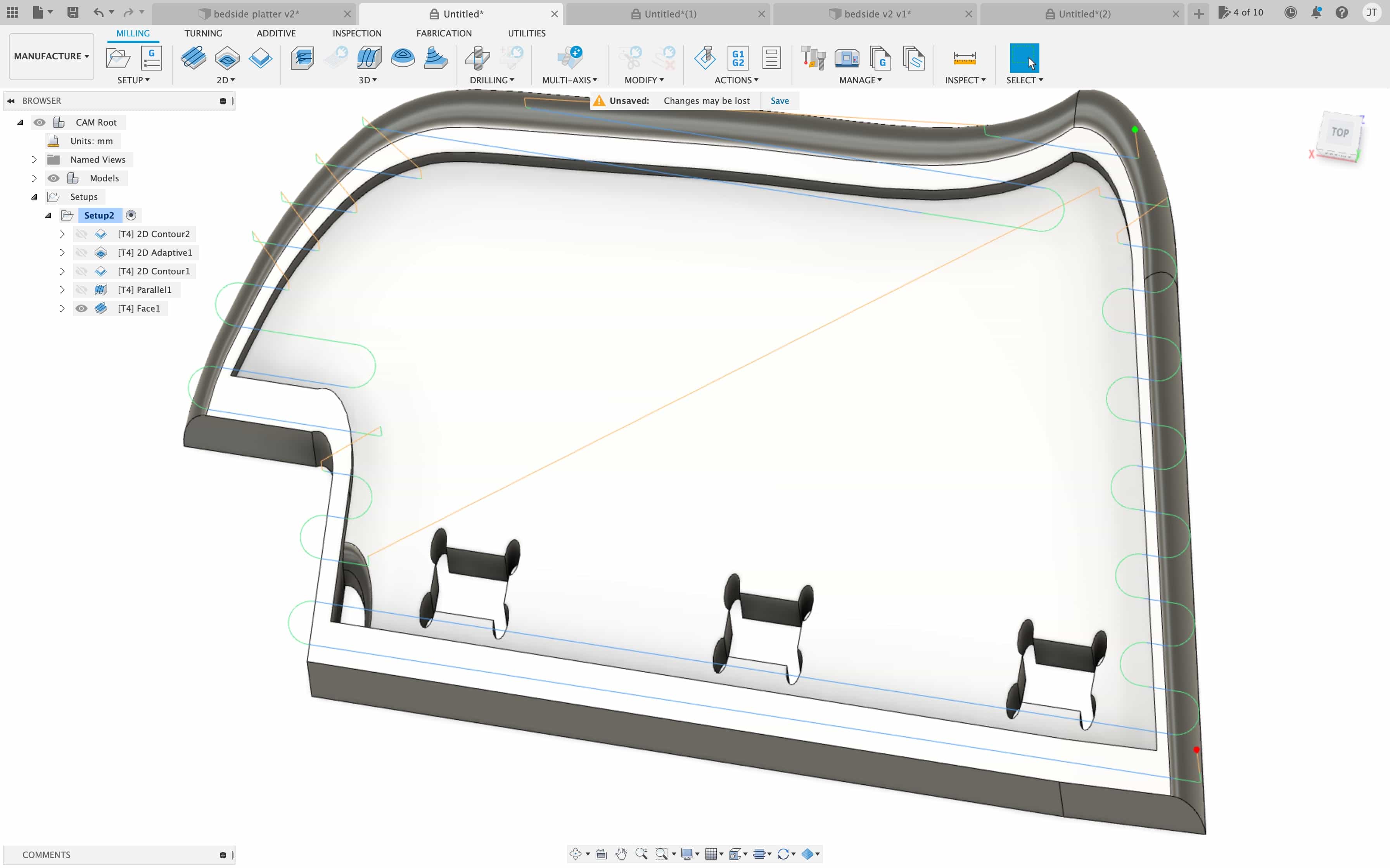
I've used the following toolpaths on this design:
- 2d contour - For the dog bone slots and the quarter-circle slot
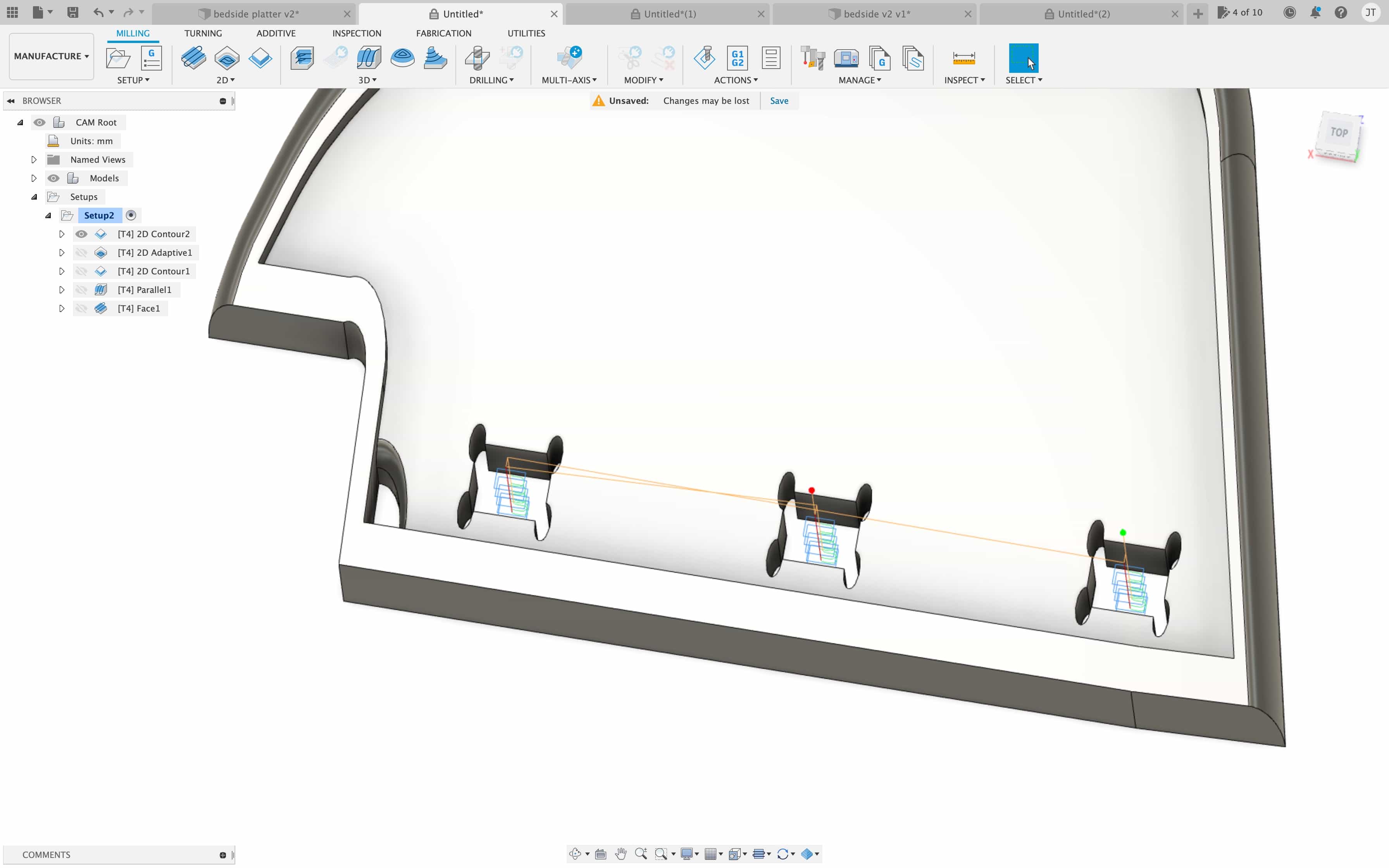
- 2d adaptive - To cut out the 4mm shelf that covers almost the entire design
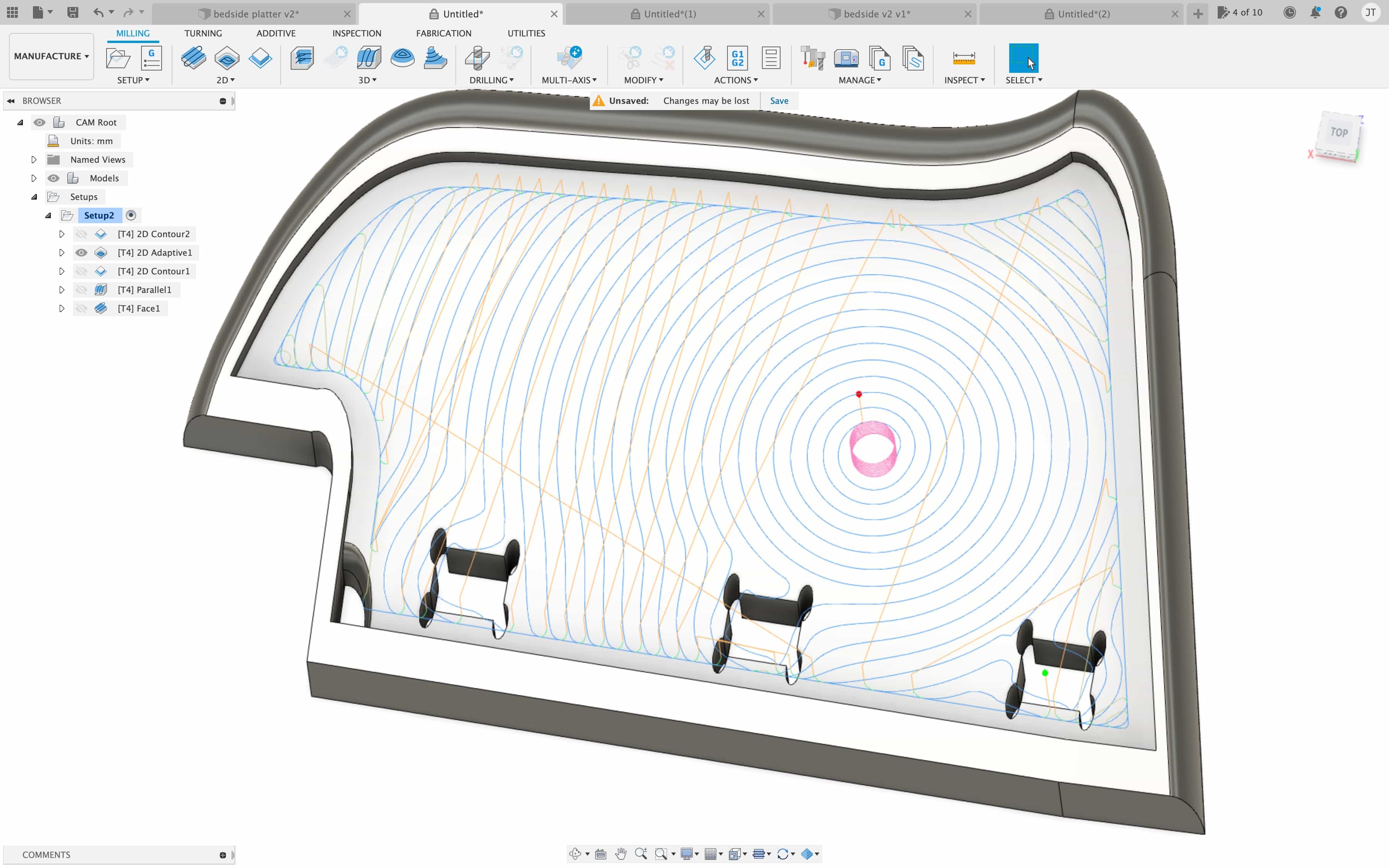
- 3D parallel - To remove some material around the sloped edges
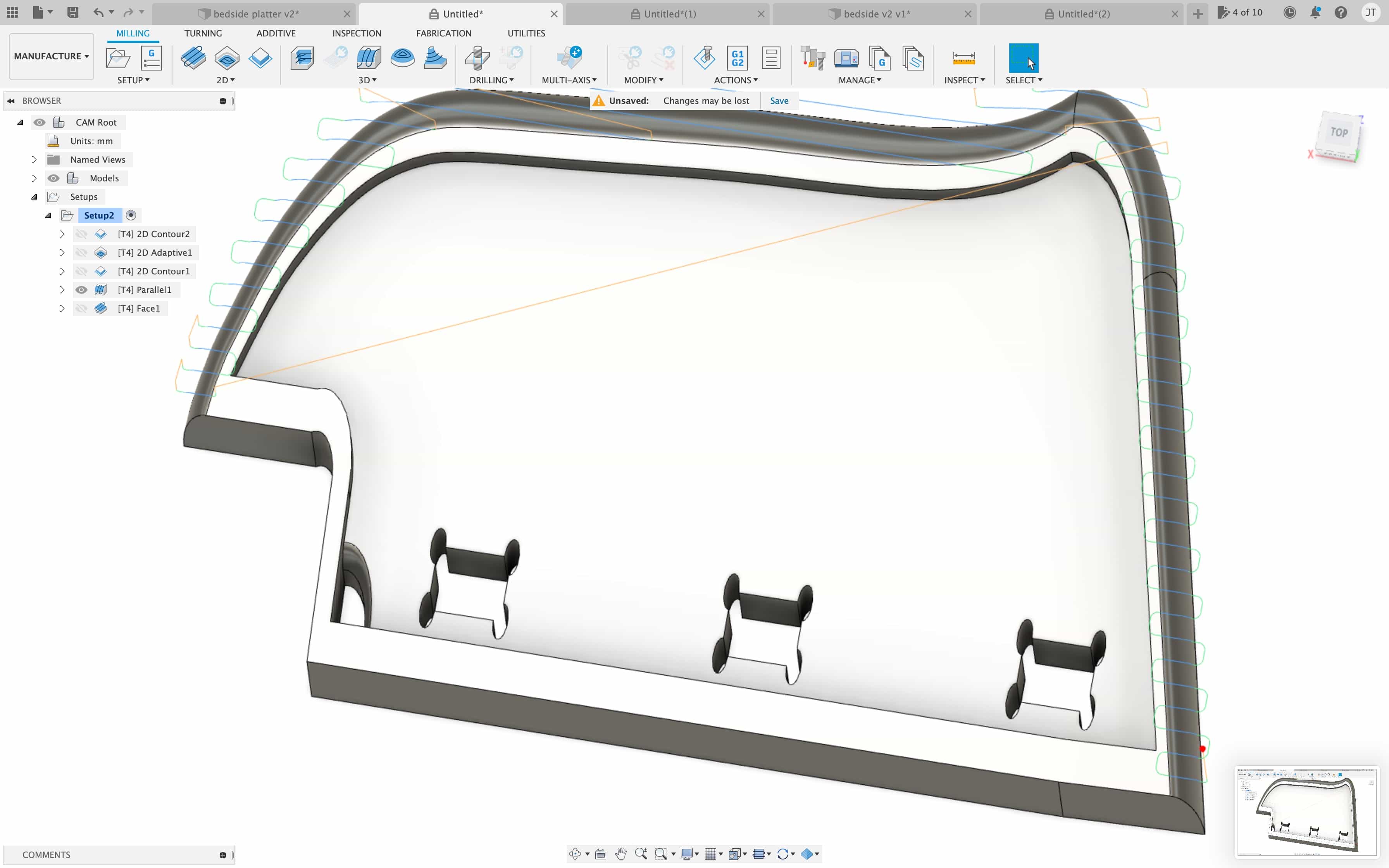
- 2D contour - To cut out the main outline of the design
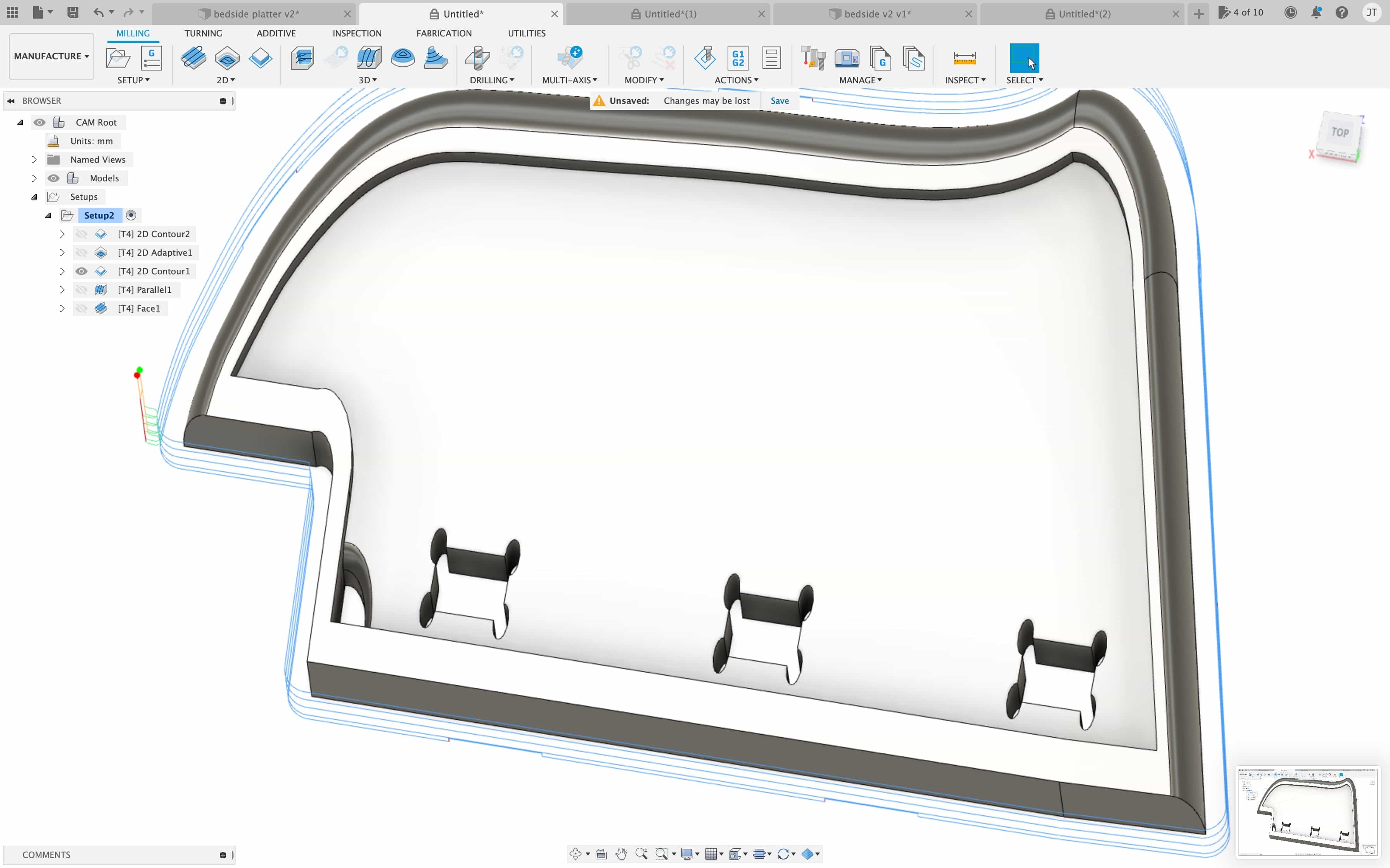
- 2D Face - To clean up the entire surface after cutting
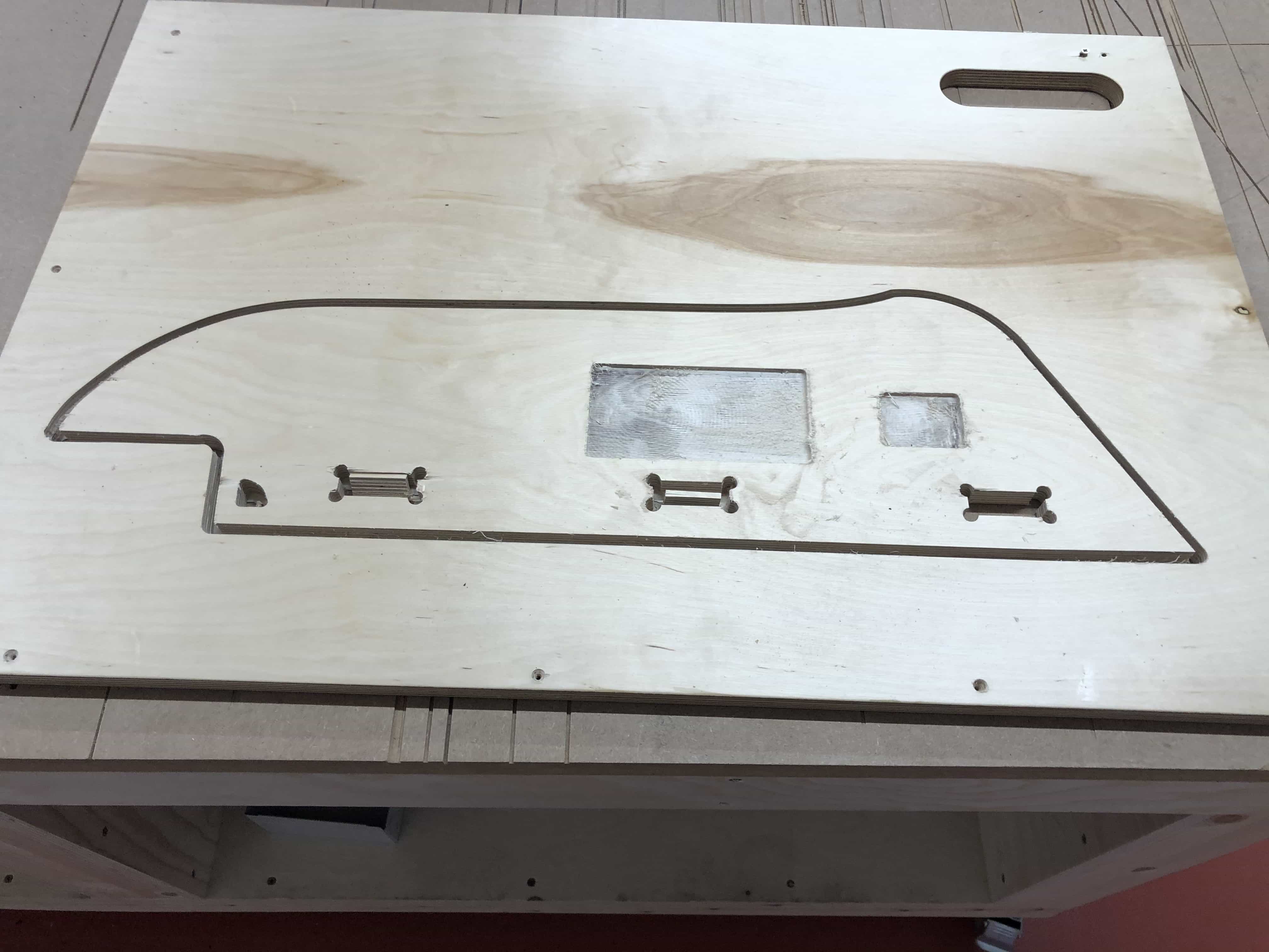
Here is the result. Its not great but its a good start:
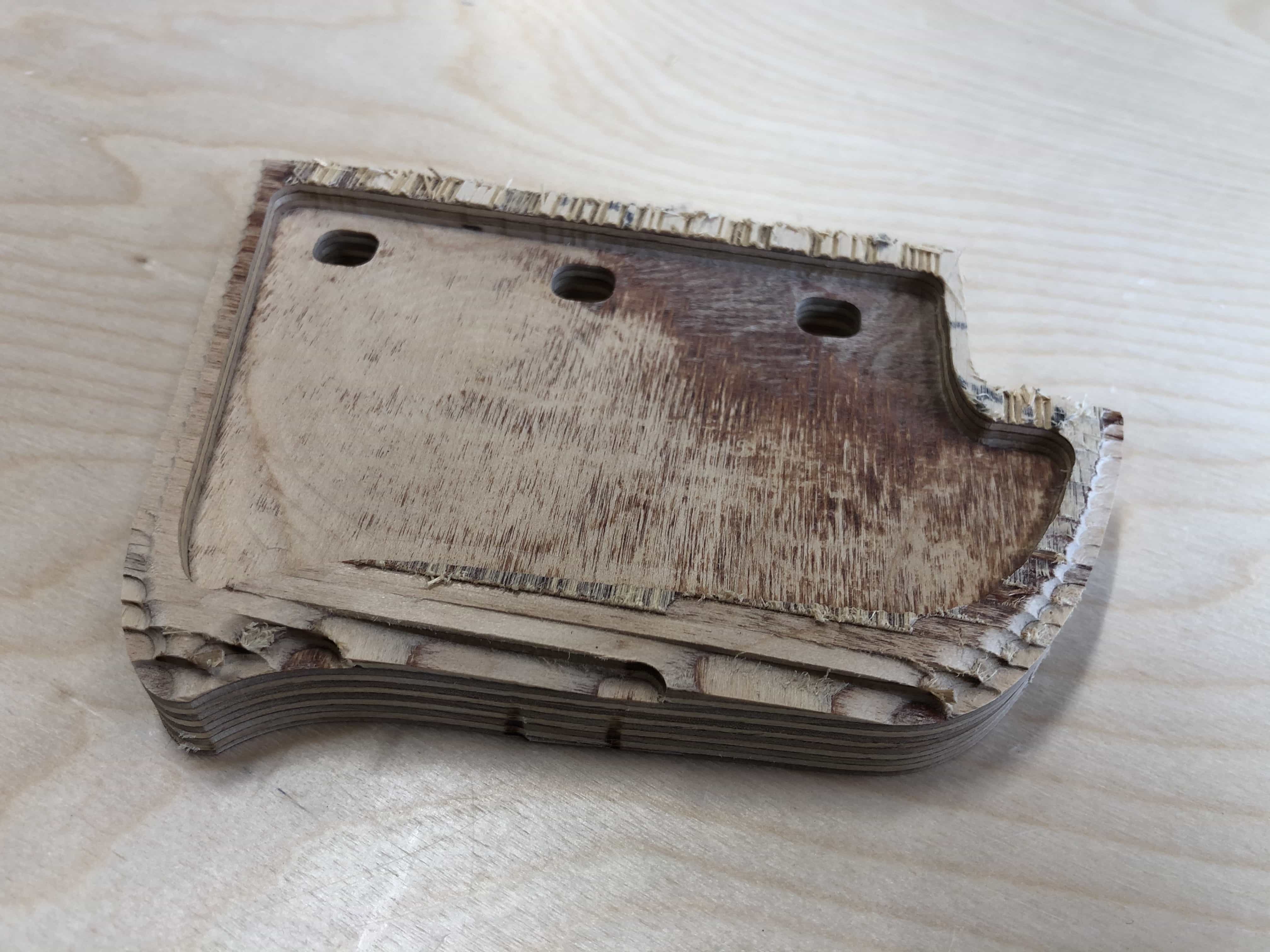
There were 2 big problems on this cut. Firstly the drill bit was too big for the geometry. I had chosen the correct drill bit for the larger design but when I scaled it down in size by 90%, I forgot to adjust the drill bit. Secondly, the machine was not calibrated correctly.
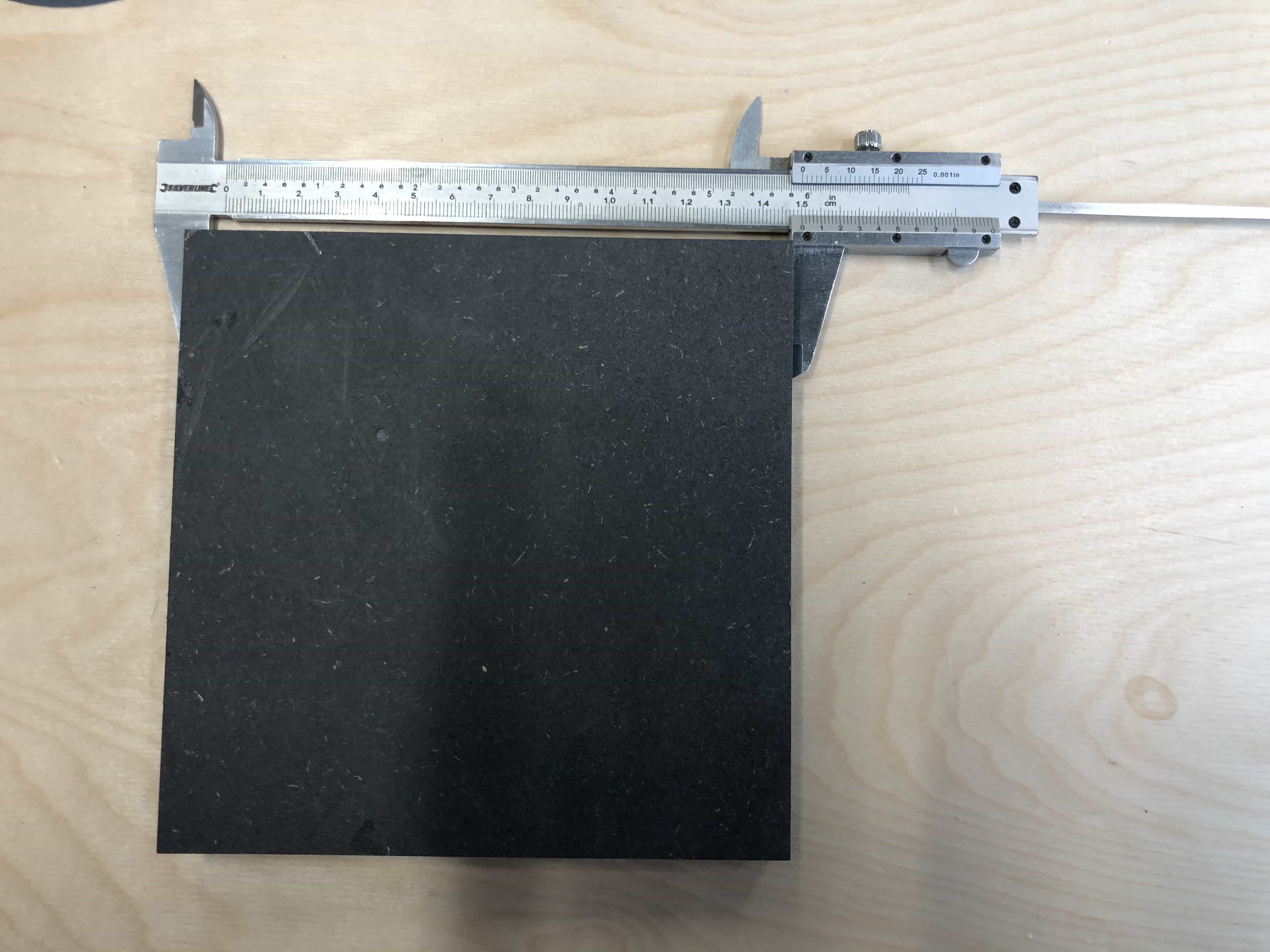
Calibration
Some of our first cuts were coming out at the wrong size. Typically they were 1-2 mm too small but by they were out by a greater amount on the x-axis.
My first thought was this was the CNC equivalent of kerf and we needed to compensate somehow in our design.
Our tutor Andrew said it would be a calibration issue and it turns out it is straightforward to re-calibrate with the following steps:
Print a test piece with known dimensions
- The bigger the piece, the more effective the calibration
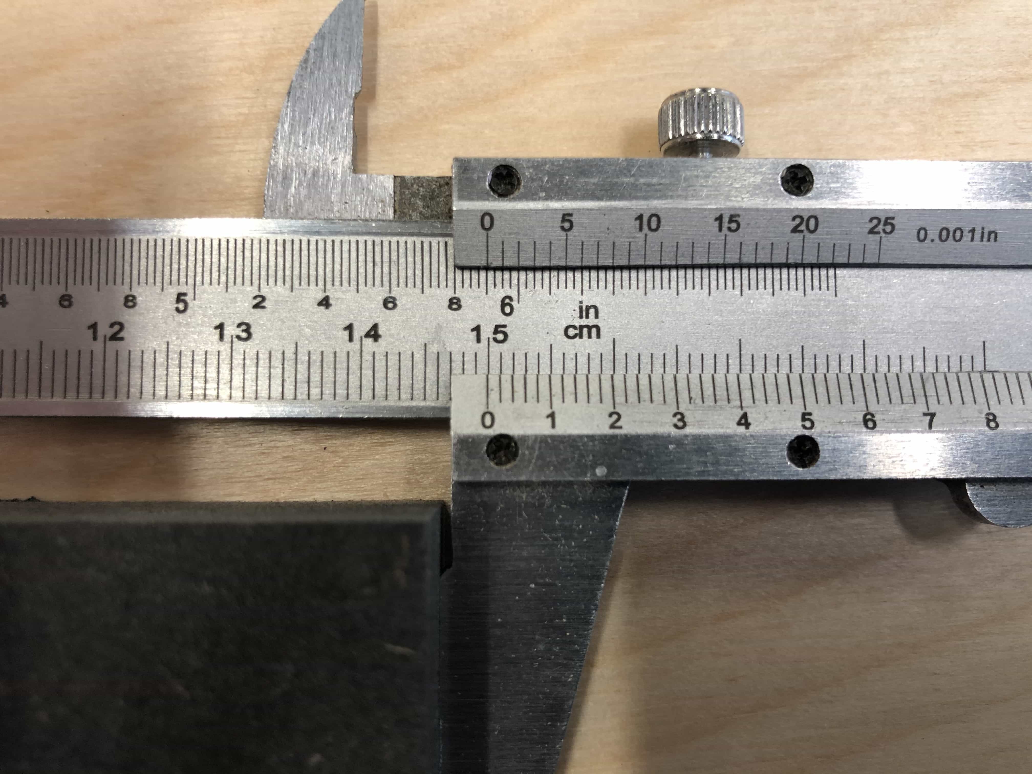
- Measurement is more accurate with calipers than a ruler
- Choose a material that is solid and cuts cleanly. MDF is not so good because it is a little squishy and can flake when cut
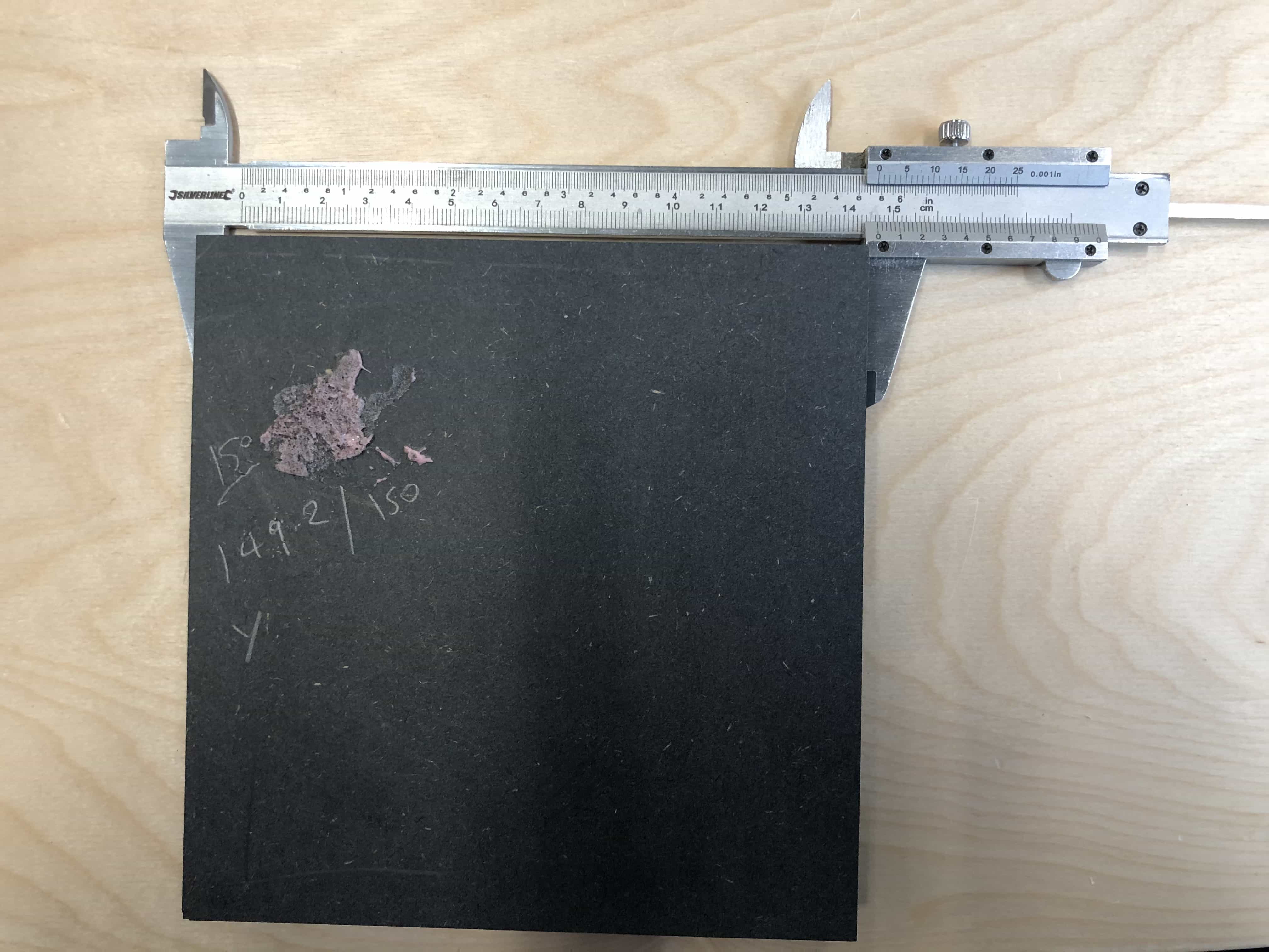
- Based on the above, we have chosen a 150mm x 150mm square of velcromat
Measure the dimensions of your cut piece. You need the X and Y dimension.
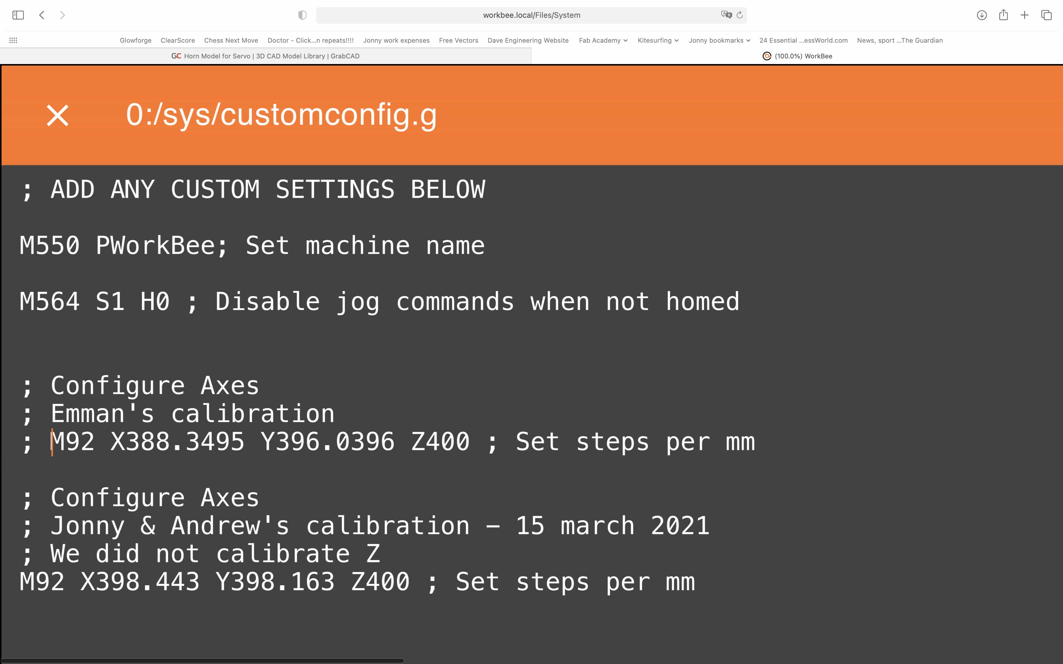
In the workbee software, click on 'system' and open the customconfig file
There will already be a line of code for the previous calibration. Copy and paste this line below.
Comment out the previous line of calibration code
Use the formula s = (i/a)*p, where:
- i = intended dimension
- a = actual dimension cut
- p = previous number of steps for calibration
- s = new number of steps for calibration
Using the formula above, determine the value of s for both axis. On the line of calibration code, replace the value immediately after X and Y
Here is our first cut. The design was 150mm x 150mm but the design was 149.2 x 146.2mm:
We followed the steps above and then re-cut the same piece. Boom! Its 150mm x 150mm:
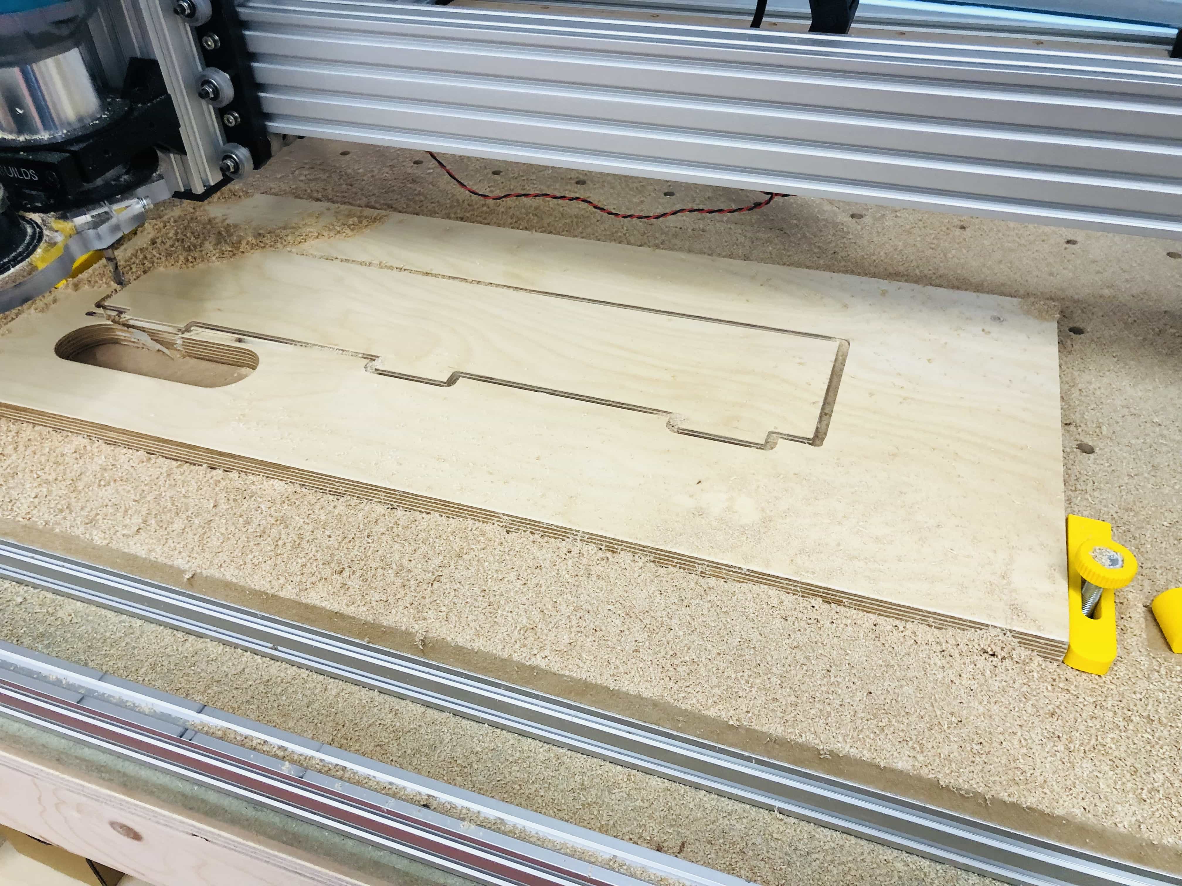
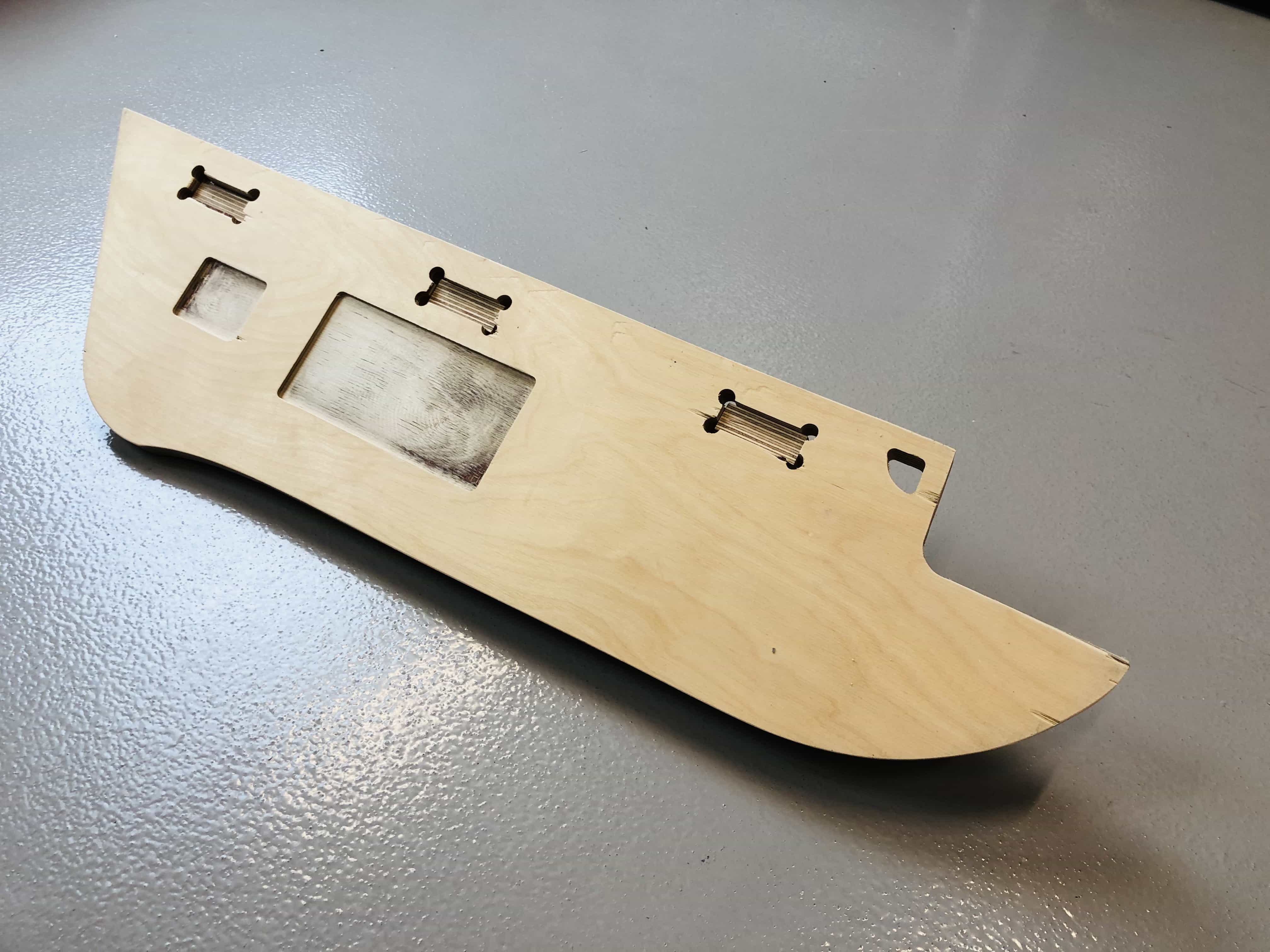
Final cut
After some more attempts on a small version of my design, I decided to simplify the big design. The curved sides are not necessary and I'm against the clock. I think its more important to have something big made and then look into creating a better finish if I have time. With that in mind, I've jumped straight into my big design. Its a little daunting when you set this going. I really don't want to screw it up when I'm using a massive and beautiful piece of plywood.
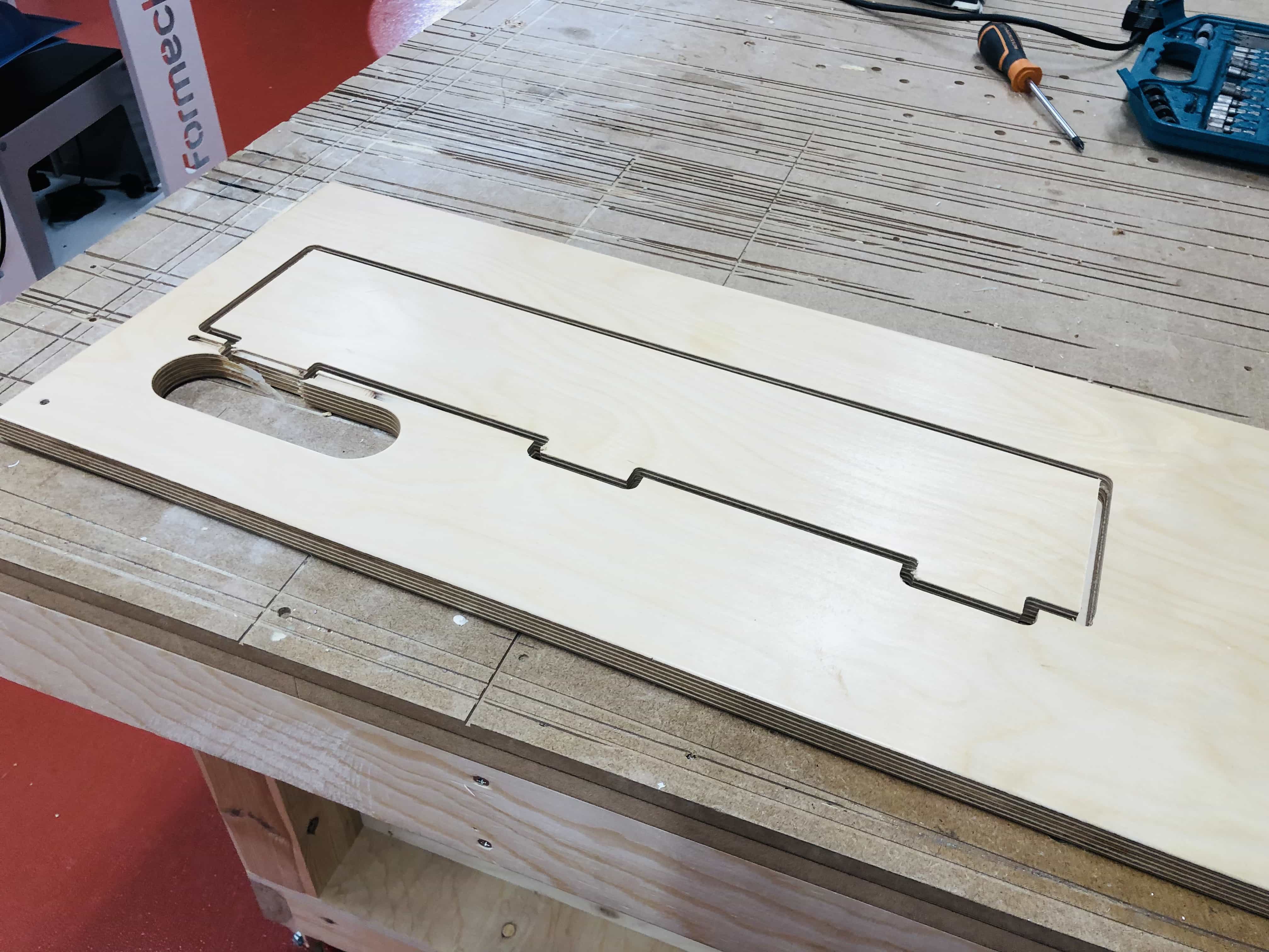
Here is my final cut. I'll need to use a chisel to cut out the tabs:
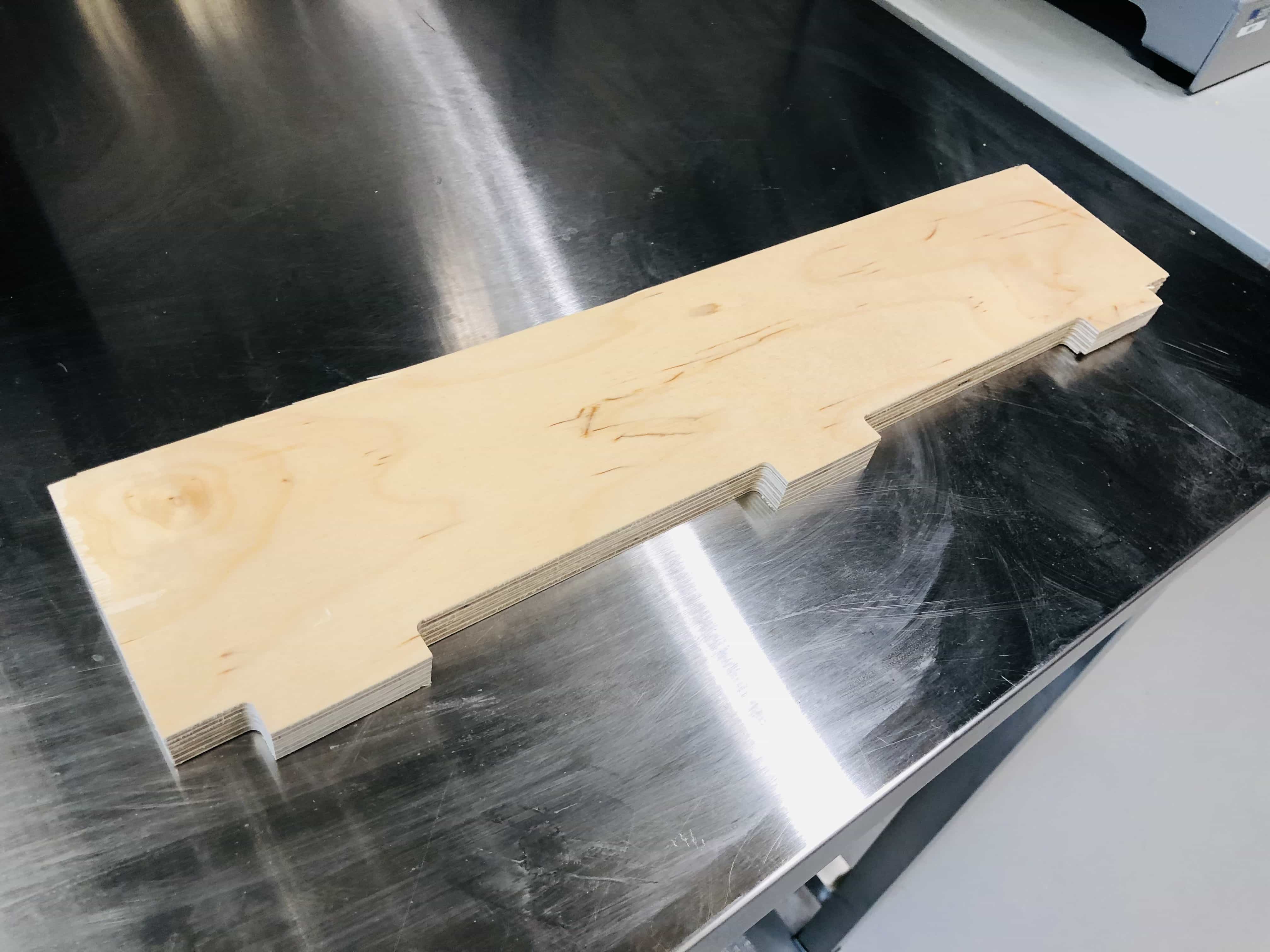
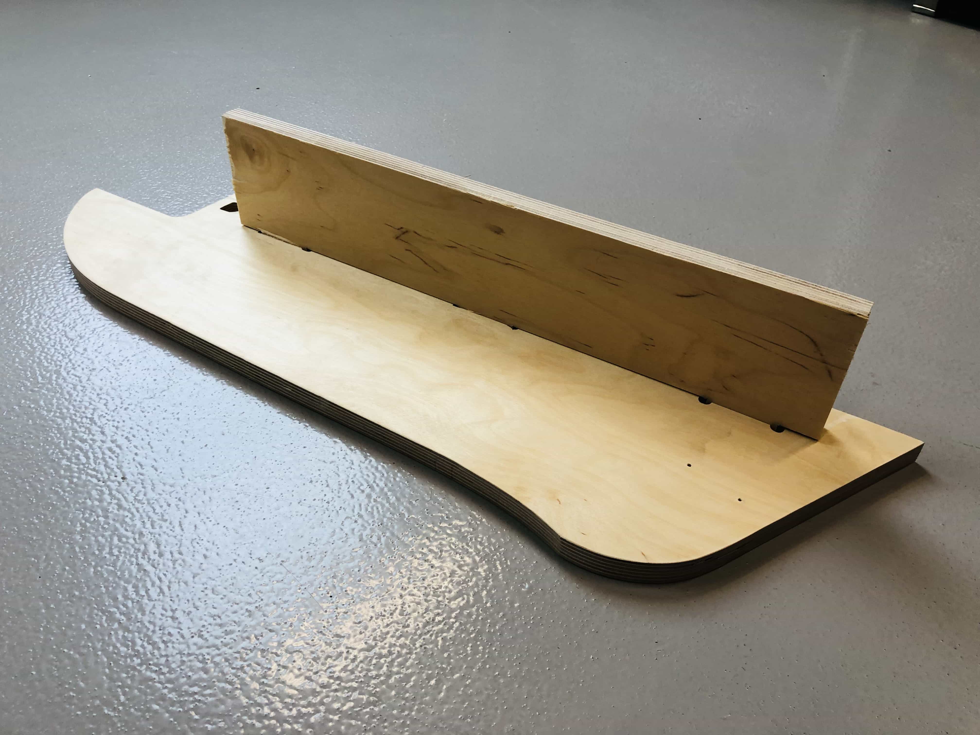
Next I shall make the interlocking section that will hold it in place inside my bed:
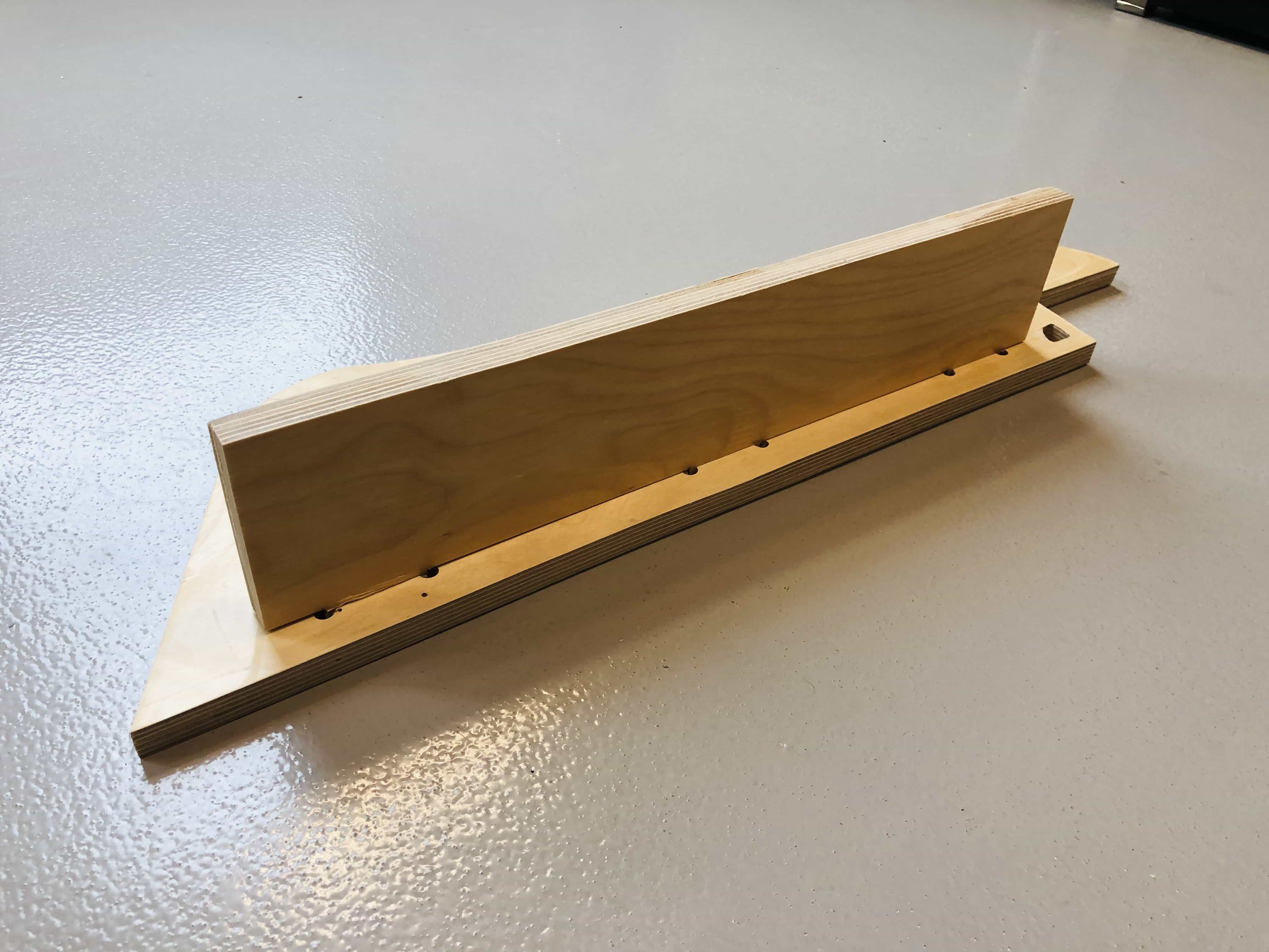
Now I shall connect the 2 parts together. I'm pleased to say that no glue was required but I did need to use a hammer to bang the 2 pieces together. It is a very solid connection:
Reflection
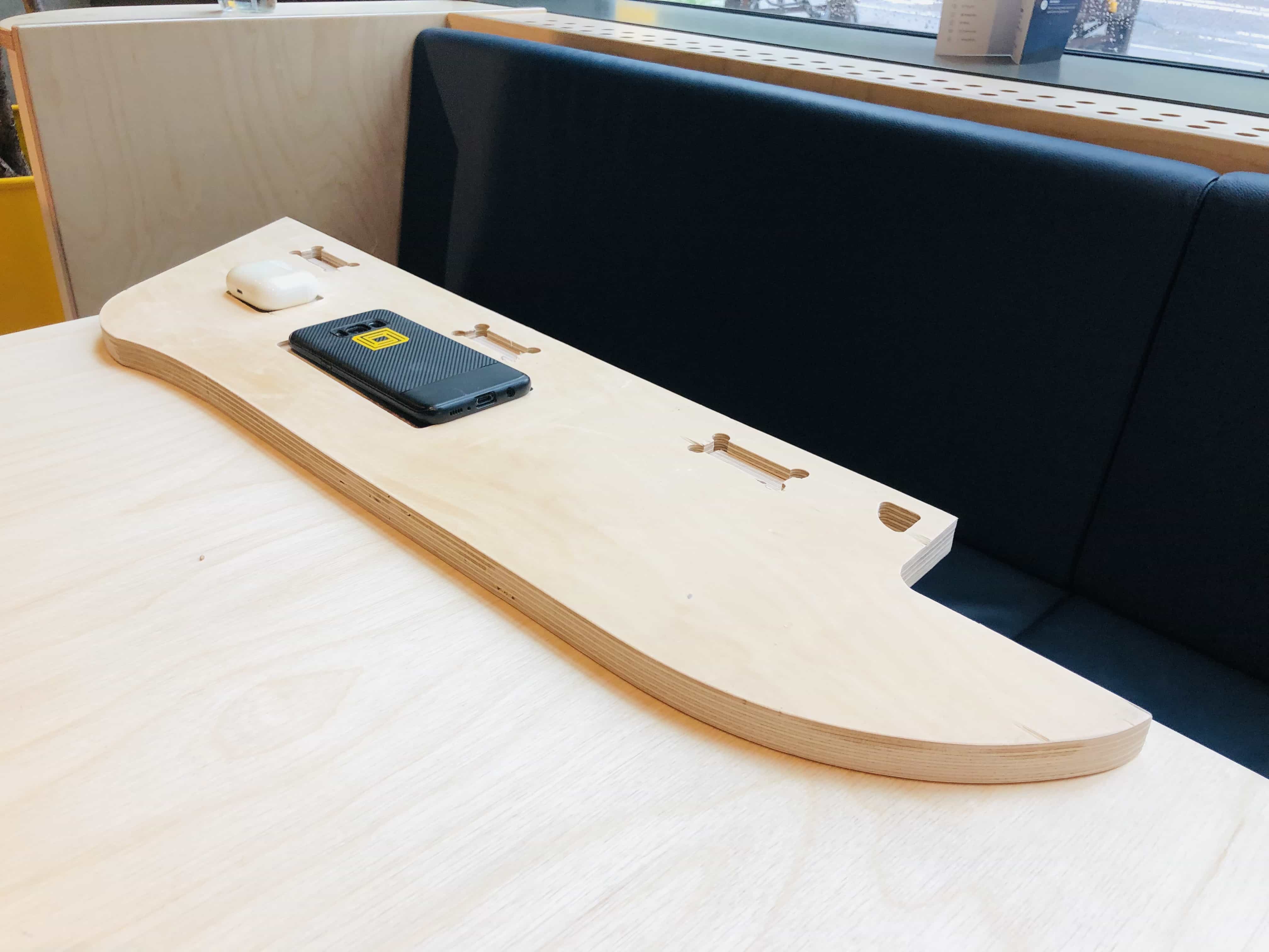
I'm happy with how this has finished. It holds the phone and airpods nicely and I think the finish is reasonably good.
If I made this again, there are some improvements I could add. Firstly, I would add dogbones to the base of the tabs. This would help get a more solid fit between the two interlocking pieces. Secondly, I would make the tabs a little longer so that they sit flush with the main surface. With a little sanding that could look really nice.
One last photo with phone airpods in their trays:
Group Assignment link
Files for download