
Week 4 - Electronics Production
assignmentgroup assignment:
      characterize the design rules for your PCB production process
individual assignment:
      make anin-circuit programmer that includes a microcontroller
      by milling and stuffing the PCB, test it,
      then optionally try other PCB processes
CNC circuit board workflow
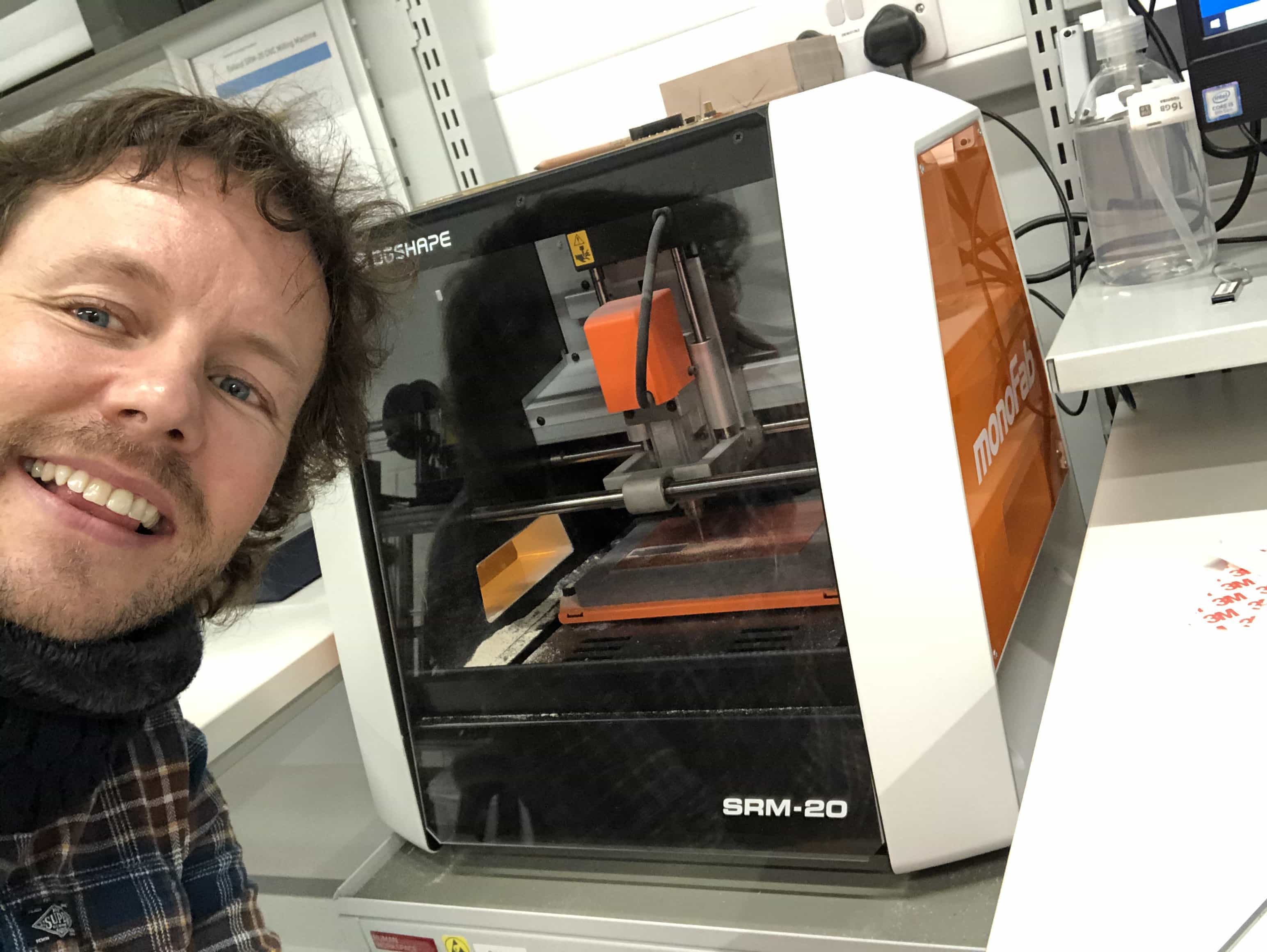
We will be using the following workflow: DESIGN - using eagle/easyeda - generates bmp or gerber file CAM - using mods - generates .rml file which is roland machine language MILLING - using SRM20 - generates bare board STUFFING - using soldering - generates finished board ready for testing TESTING - using multimeter - generates a big smile when it works! Below is our monoFab SRM-20 CNC machine:
Using modsproject
Mods is the software we'll use to generate a type of gcode for our CNC machine. Its the CNC equivalent of Cura. You use mods directly in your browser and the URL is modsproject.org. This software is not super intuitive and i found the navigation a little frustrating. It zooms in incredibly quickly and so you either need to use a mouse with a click wheel or learn to be extremely gentle with your trackpad. This is the homepage you'll see when you enter the site:
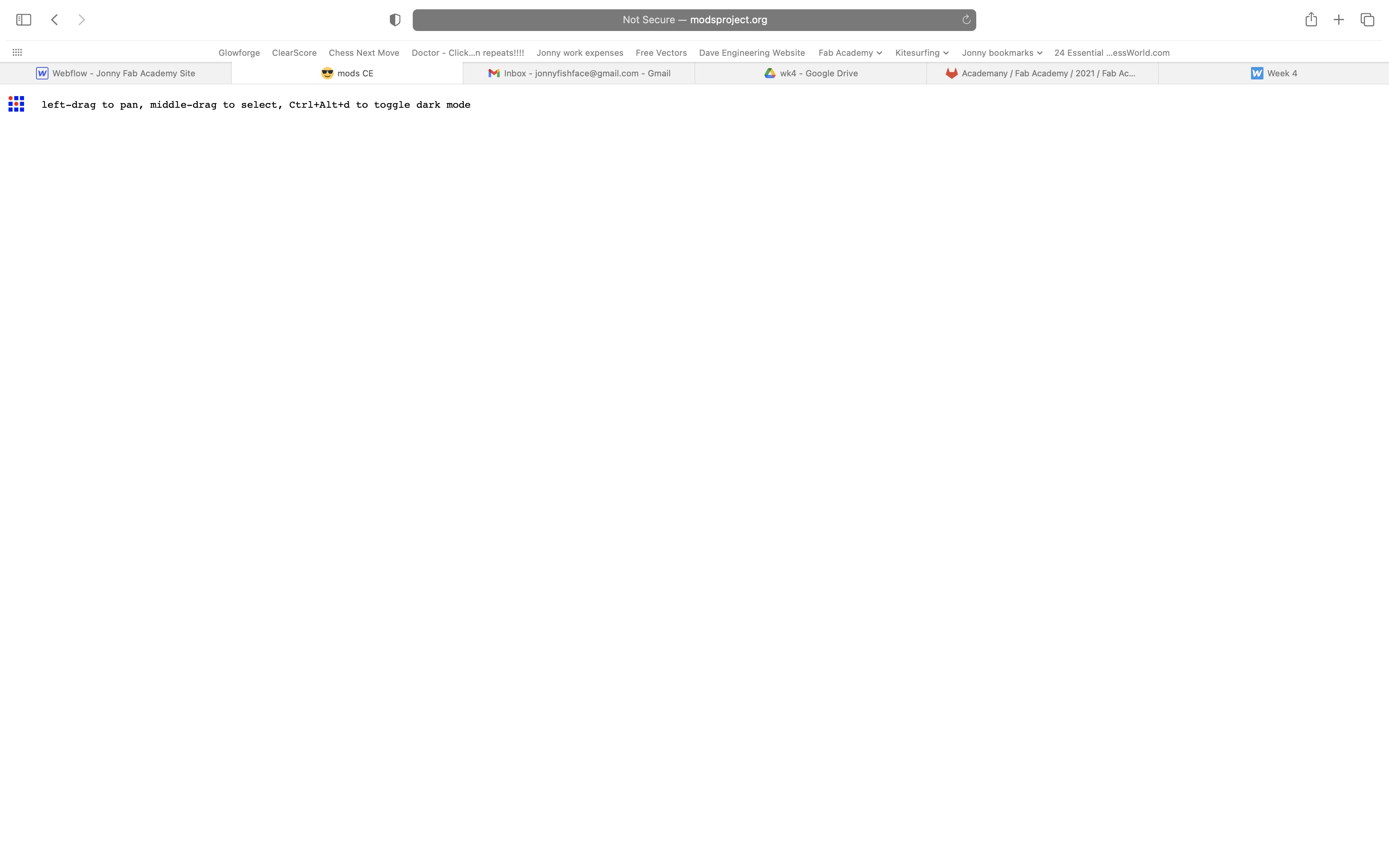
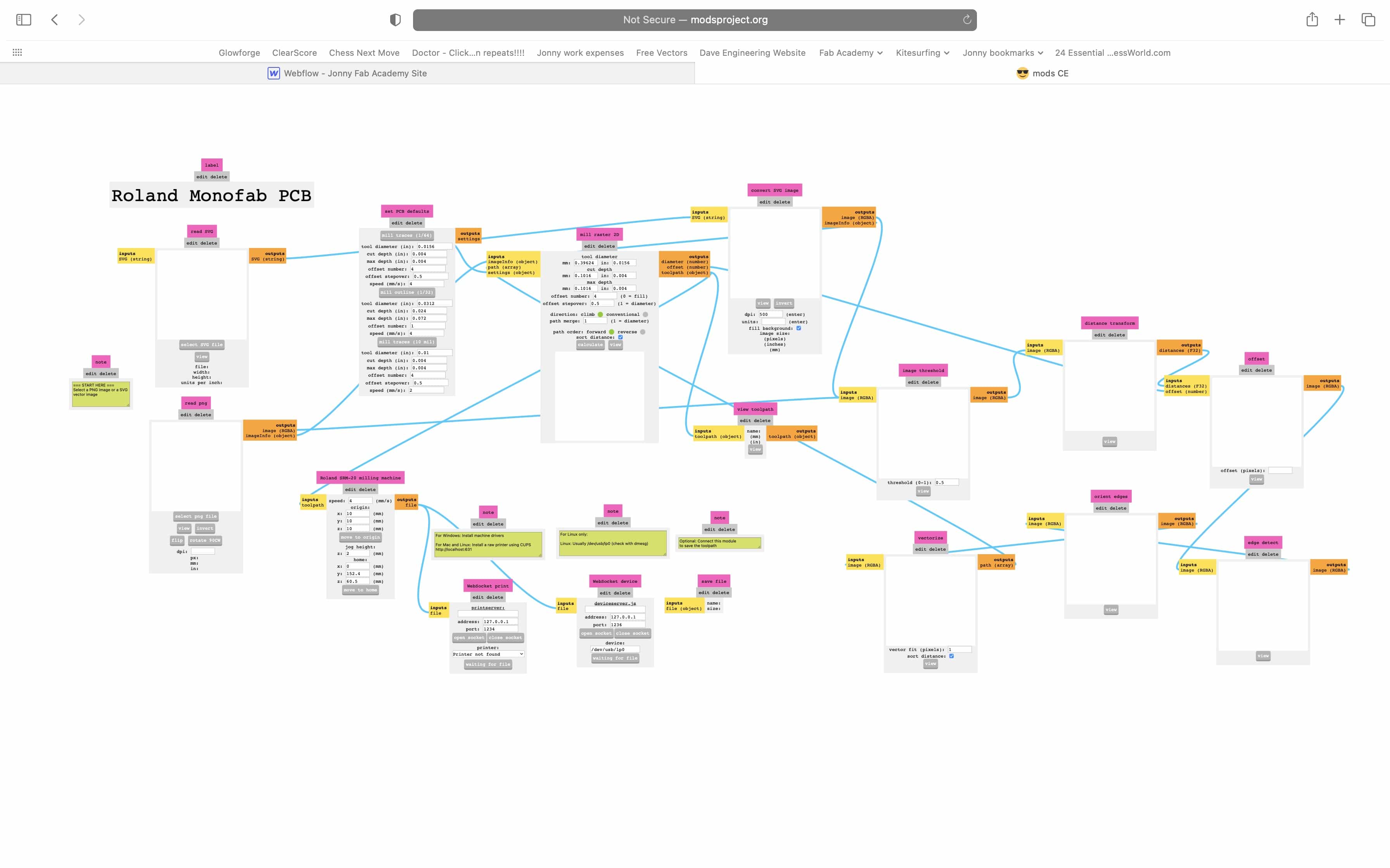
Yep its almost a completely blank page. You need to the following: 1 - Two finger tap to bring up the menu 2 - Select 'programs' 3 - Select 'open programs' 4 - Find the 'SRM-20 Mill' and select 'PCB'. You should now be looking at the following screen:
Trackpad control
Ok I've cracked it. If you want to use your Apple trackpad with mods, rather than sliding your fingers up or down to zoom in or out, you need to place your two fingers and roll. If you roll them forwards or backwards in a gentle motion, it will control the zoom at a sensible level.
FabTinyISP
We shall be working through Brian's tutorial to make this FabTinyISP:
Setting up your file
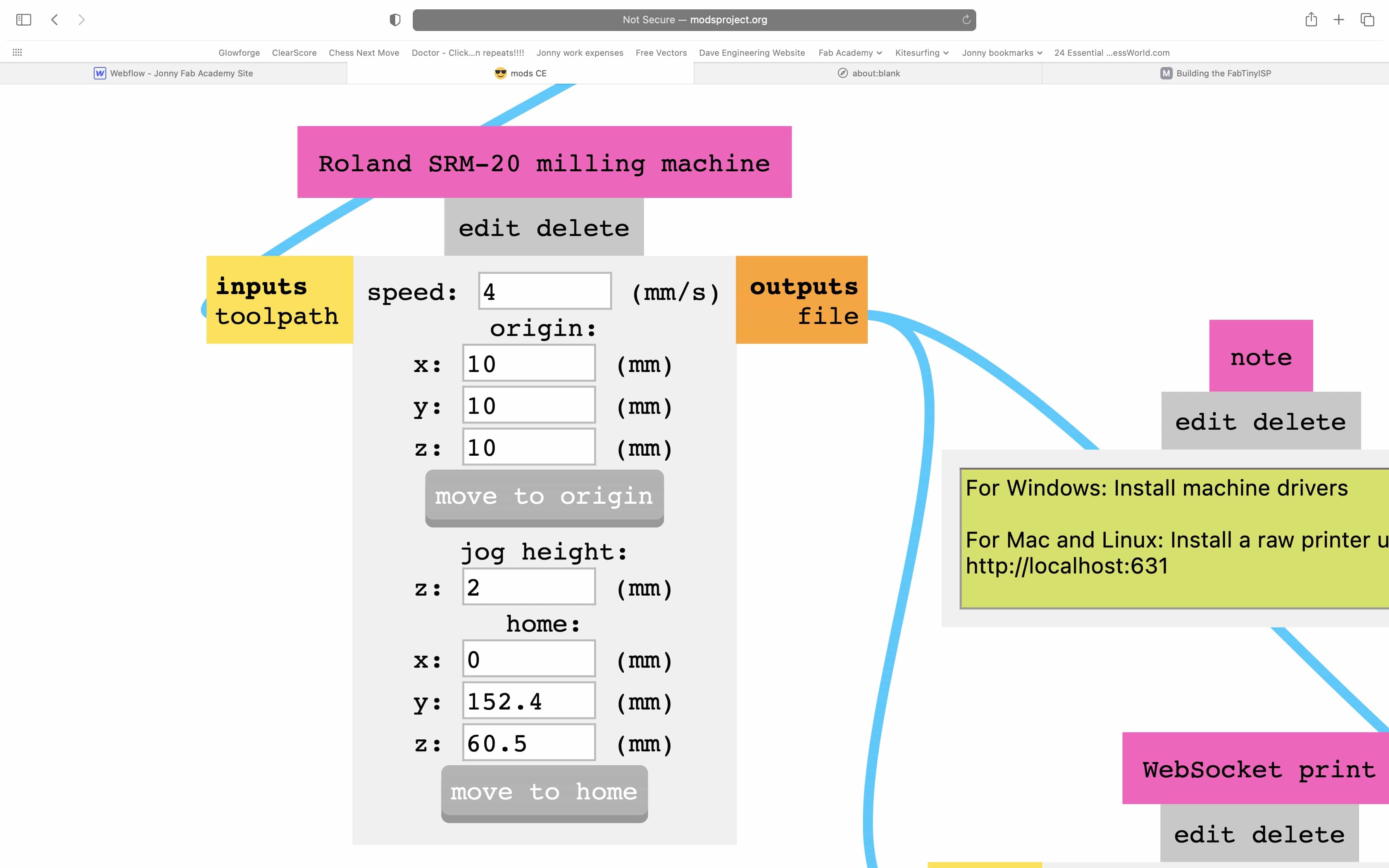
1 - Start on the left side of the screen and click to upload either an SVG or PNG file. We shall be using the PNG file for the FabTinyISP 2 - The design will appear. Do a quick sense check to make sure you have the correct file in th expected dimensions 3 - We will start by milling the traces. There are some pre-saved settings available, should we wish to use them. To do this, click on 'mill traces' and the data will push over to the 'mill raster' box. If you prefer, you can type your own settings directly into this box. 4 - Set the drill bit size you're using which will be a 0.4mm for the traces. Now set a cut depth which will be 1.2mm for this design. Set the max depth to this value also. 5 - You'll need to set an offset number. This is the number of paths it will do around the first path. Its not like a laser cutter doing multiple passes over the same path. This is the same path but offset and so its making a thicker gap around each piece of copper. If you set offset to 0 it will take away everything but the traces. (This makes for a lovely clean look to your board but it takes a little longer to mill) We'll be using an offset of 3 for our design today. This will make it easier to solder than if we had used an offset of 1 or 2. 6 - Press view and and you'll be able to see the tool path. You could do a quick sense check here and make sure everything looks about right. 7 - Go to 'Roland SRM-20 machine'. Make sure the origin is set to 0/0/0. This is really important. Technically there could be situations where you wish the origin to be something different but for our design today and most future instances, it should be 0/0/0. 8 - Set the machine jog height. This is the height the milling tool rises to when moving from one place to another. If your material was not flat, you may wish to increase this further but for our design, we'll use the default of 2mm. 9 - Connect the machine settings to the 'save file' box. This is not super intuitive. You need to click on the word 'file' in each of the boxes you wish to connect. 10 - This is small but important. I missed it twice. You need to disconnect the machine settings from the 2 boxes it was already connected to. As before you do this by clicking on the word 'file' in the 2 boxes that are currently connected. If you don't do this step, the file will not download and you will get no error message to help you bug test it. 11 - Click 'calculate' on the 'mill raster' box and your file will download. The file format is .rml which is Roland's equivalent to gcode.
Do not forget to set the origin to 0/0/0
In spite of the reminder in my guide above, I forgot to set the origin to 0/0/0 in the mods project software. The CNC mill just moves around 20mm above the material. A big thumbs down moment:
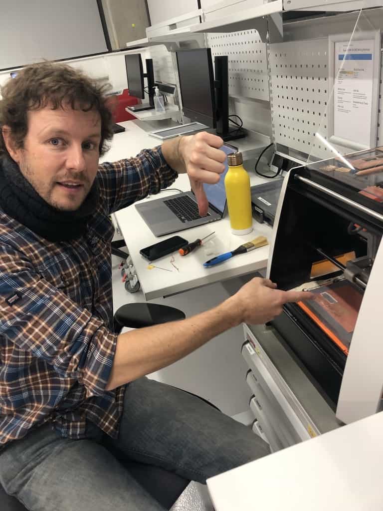
Its not difficult. Just set the origin to 0/0/0 in the Roland machine settings:
Setting up the Roland SRM-20
Same as the laser cutter, you need to setup the computer and machine separately. The software we use is called Vpanel. Set up the machine as follows: 1 - Make sure the plate is clear of any dirt or debris. 2 - Take a look at your material and make sure its at least reasonably flat. 3 - Take your material and use the tape next to the CNC (a special extra sticky double sided tape) and put a few strips onto the back. 4 - Stick your material onto the bed and use your fists to make sure it is stuck down securely and nice and flat. Use your fist to squash out any bumps. 5 - Locate the milling bit that is the correct size for your design. You may want to use the USB microscope to ensure the bit is not broken. 6 - Use the allen key to undo the grub screw. Be careful, there are 2 silver screws that look like grubscrews but one of the screws is an excellent red herring designed to confuse you. (and counter balance the weight of the real grubscrew) 7 - Insert your bit into the machine, holding it at the tip as you do so. Be careful, don't drop the bit. They are expensive and very delicate.
Setting up VPanel on the computer
1 - Open Vpanel software. 2 - It should automatically connect to the CNC but if not, check that the CNC is turned on. You'll need to use FabMan to power it up but this is not enough. You also need to press the power button on the top right. 3 - You can control all 3 axis using the software. You can set the distance that the bit moves with each press. 4 - BE CAREFUL - When using continuous or X100 mode there is risk you could push the bit down into the material. The bits are very delicate and expensive. 5 - Move the axis to the X/Y location which you wish to be the left bottom corner of your design. Now press the XY origin button to set this location to 0/0. 6 - Drop the Z axis towards the material. Stop when you are approximately 10mm from the material. 7 - While holding the bit, undo the grub screw and drop the bit to the material. Now press the Z origin to set to zero. 8 - IMPORTANT - Raise the bit back at least a few millimetres. Its important it is not touching the material when it starts spinning. 9 - Click on 'cut'. Delete the previous file if it exists and then add your own RML file. 10 - Press 'go' (or whatever that button said!) .Put the bit into the correct position on x/y axis and then undo grub screw, drop the bit to the material. Then drop the z axis a couple of notches. You need to leave enough space that you can drop z further when you start cutting.Now set all origins to zero.Press output and select your FML file. Now you need to cutGo back into VpanelMake sure the origin is set to 0/0/0 if thats what you used on the millChange the bit to 0.8. Now you’re doing multiple passes across the same path, going deeper each time
Cutting the outline to the board
The process above was used to cut the traces on the board. Now we need to cut the outline of the board. We follow the same process as above, with the following changes: 1 - Change the bit size in Mods to 0.8mm 2 - Change the cut depth to 0.6mm and set it to do 3 passes (Bare in mind this is different to a laser cutter where it is doing the same thing repeatedly over the same path. With the CNC machine, each subsequent path is going 0.6mm deeper than the previous. 3 - Export the file as before. This is your new file to use in Vpanel. 4 - Change the bit in the CNC to 0.8mm. Make sure to put the 0.4mm bit back immediately. Seriously, don't just jump to the fun part of drilling the board. Put that bit away safely first! 5 - Follow the same procedure as above to calibrate the Z axis. DO NOT TOUCH THE X/Y AXIS!! 6 - Use Vpanel to load the new file and click 'output'.
Broken bit
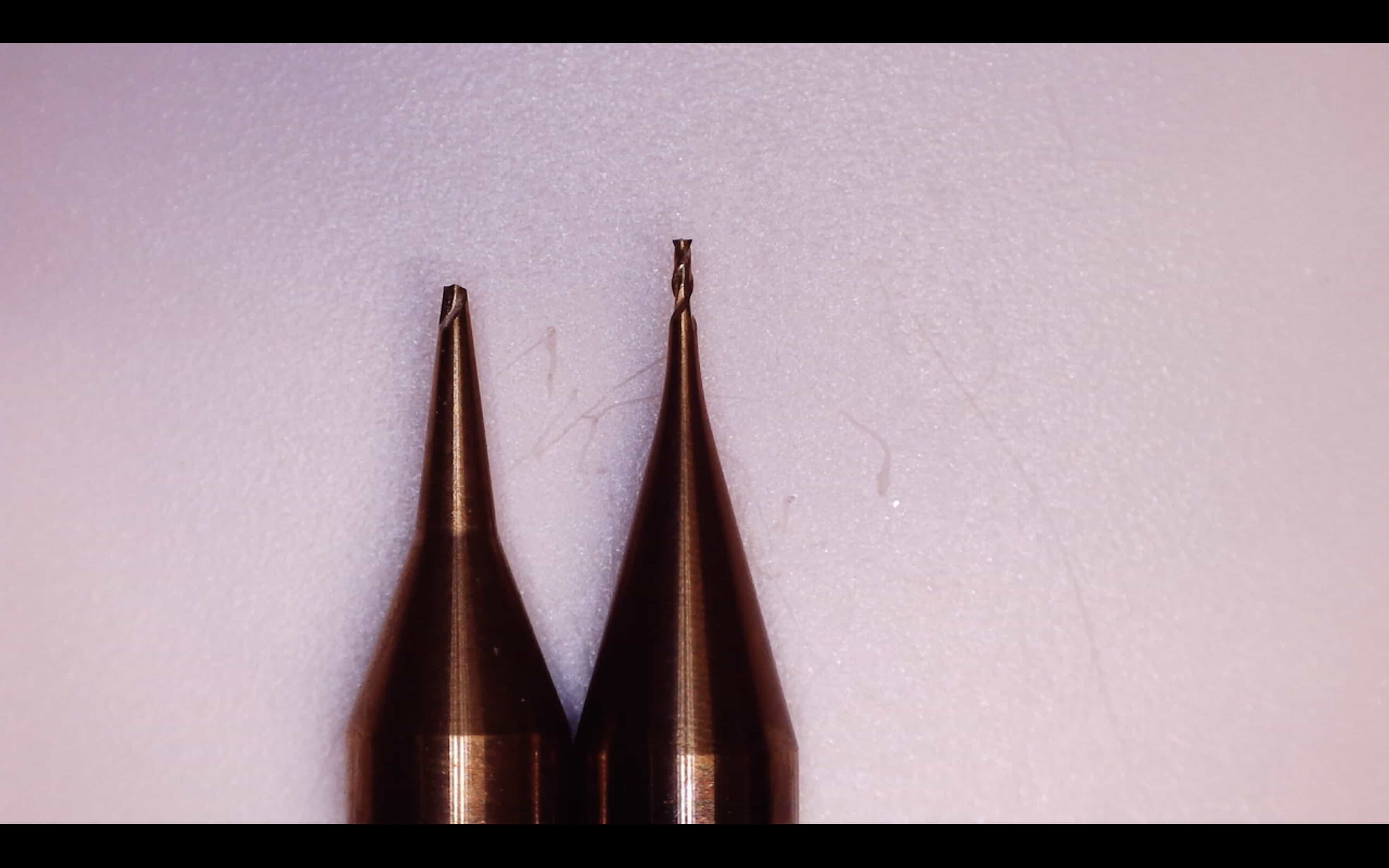
My lab partner broke the 0.4mm bit. It felt like a good opportunity to record a photo of a broken bit next to a good bit. Its always worth having a close look before you use a new bit. Its hard to see that they're broken without looking very closely. If in doubt, compare it next to another bit that you know for sure is brand new.
SMD soldering technique
Best practice SMD soldering technique is: 1) Put a very small amount of solder onto just one pad of the required component. 2) Touch the solder to make it go as flat as possible 3) Lay your component into place 4) Touch the solder so it sticks to the component 5) Add solder onto the other side (or other pins if there are more than 2) 6) Add a drop more solder to the first pad.
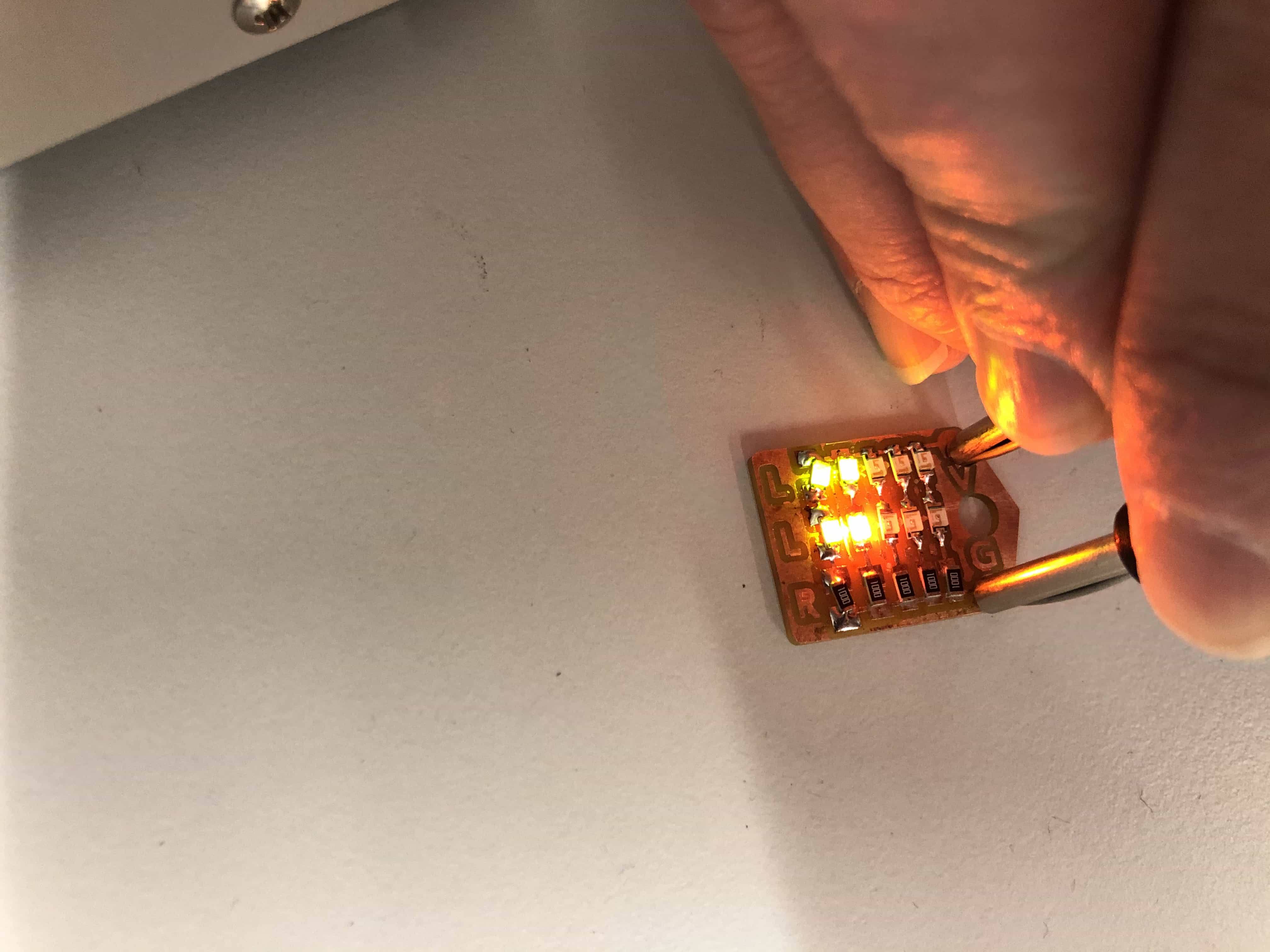
I've done a reasonable amount of pin hole soldering before, but I've never used surface mount components before. Andrew suggested I start with the small board below as a practice run. This board requires 5 resistors and 10 LEDs. I dived right in:

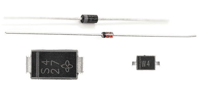
Diodes are directional!
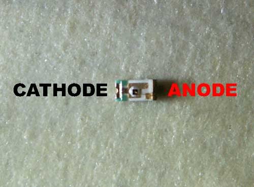
I totally forgot to check the direction of the LEDs. I know from through hole soldering that LEDs are directional but I stupidly didn't think of that with the SMD version. I will need to de-solder half of these LEDs and re-do them. You can check the direction of an SMD diode by looking closely at the casing. There will be a line on the side of the cathode. You may need a microscope to view it:
Its important to remember that Anode is positive and cathode is negative. I find it easiest to remember this by picturing someone called Cathy who is a bit of a negative ninny.
I needed to de-solder several LEDs and I did this with a combination of solder sucker and solder wick. I received a free solder sucker with my home soldering iron but I struggled to use it effectively. I think I was not putting the tip in close enough to the solder. I had not realised that the tip is heat proof. It looks like plastic rather than silicone and so it didn't occur to me to put it near a 340 degree iron! Actually though, its totally fine to do so and it is really effective for large bits of solder. It seems best to follow a 2 step procoess: De-solder process: 1 - Remove large pieces with the solder sucker 2 - Remove small pieces with the solder wick

4 of the LEDs and re-soldered with correct direction. I then tested with a bench power supply and it worked!
Now its time to try soldering our ISP board. Our tutor Andrew recommended that we lay the components out on double sided tape. This was great advice as these components proved to be super fiddly:
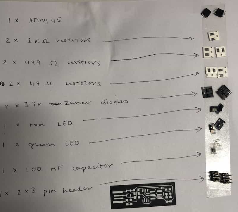
Be careful when selecting components
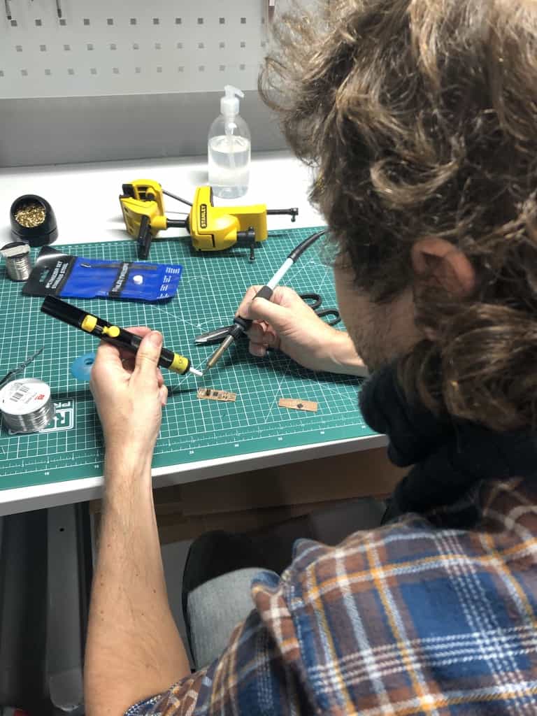
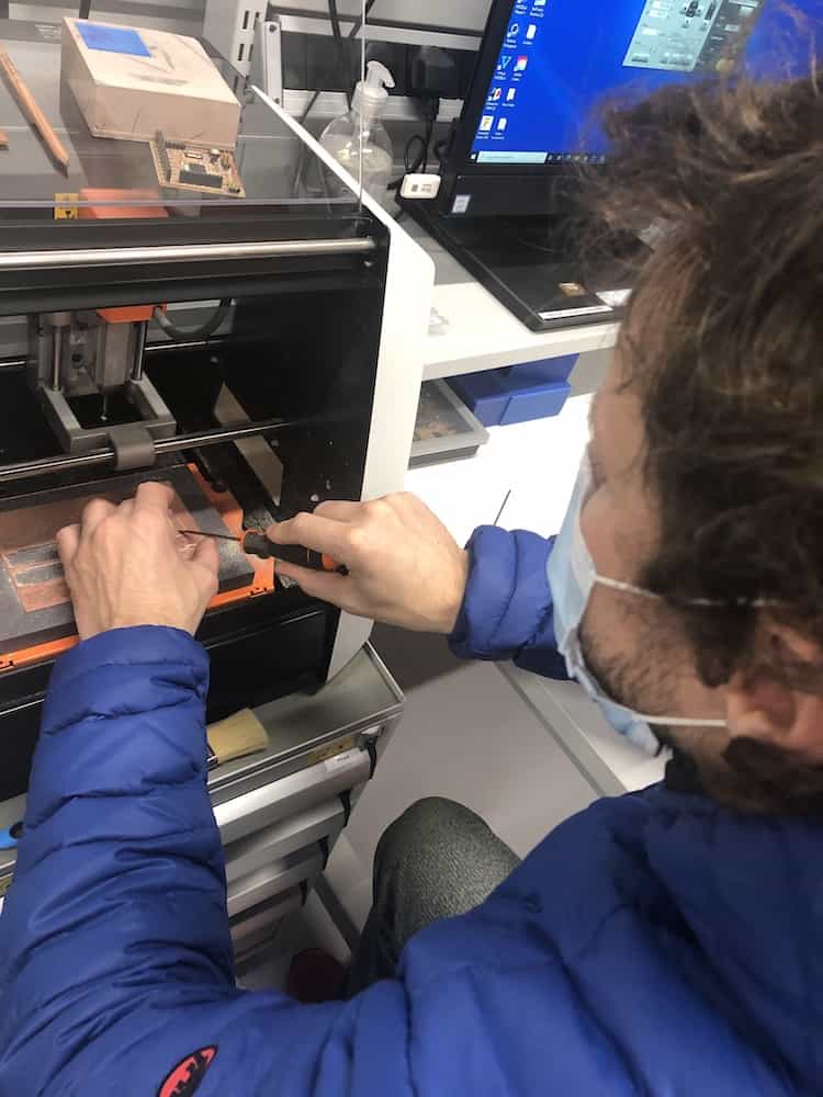
Note to self - look more carefully at the resistor value before you start taking them out of the packet. I took the 499K and the 49.9 resistors out of the packet before realising they were not 499 resistors. I'm often rushing parts of the workflow like this one. I guess its boring and I just want to start soldering asap, but taking a deep breath and taking some time to get the correct components first time will save me a lot of time in the long run. Here is a photo of me soldering the components onto our ISP board:
Close-up view of my soldering
We used a USB microscope to take a close view of the soldering. To use the microscope: 1 - Connect to your mac using the USB cable 2 - Open quicktime 3 - Click the dropdown menu to select source and find the USB microscope Here are the shots of my soldering:
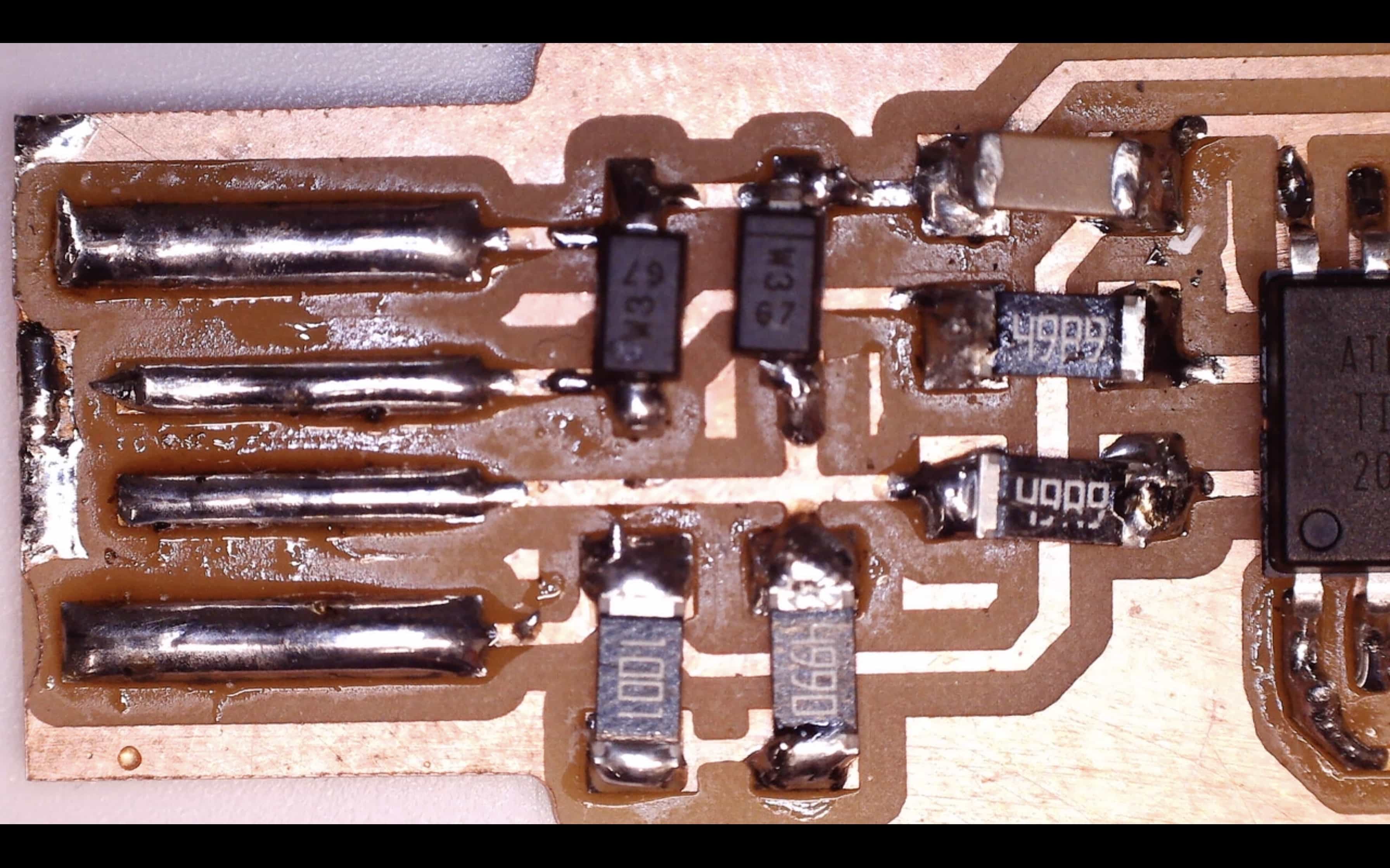
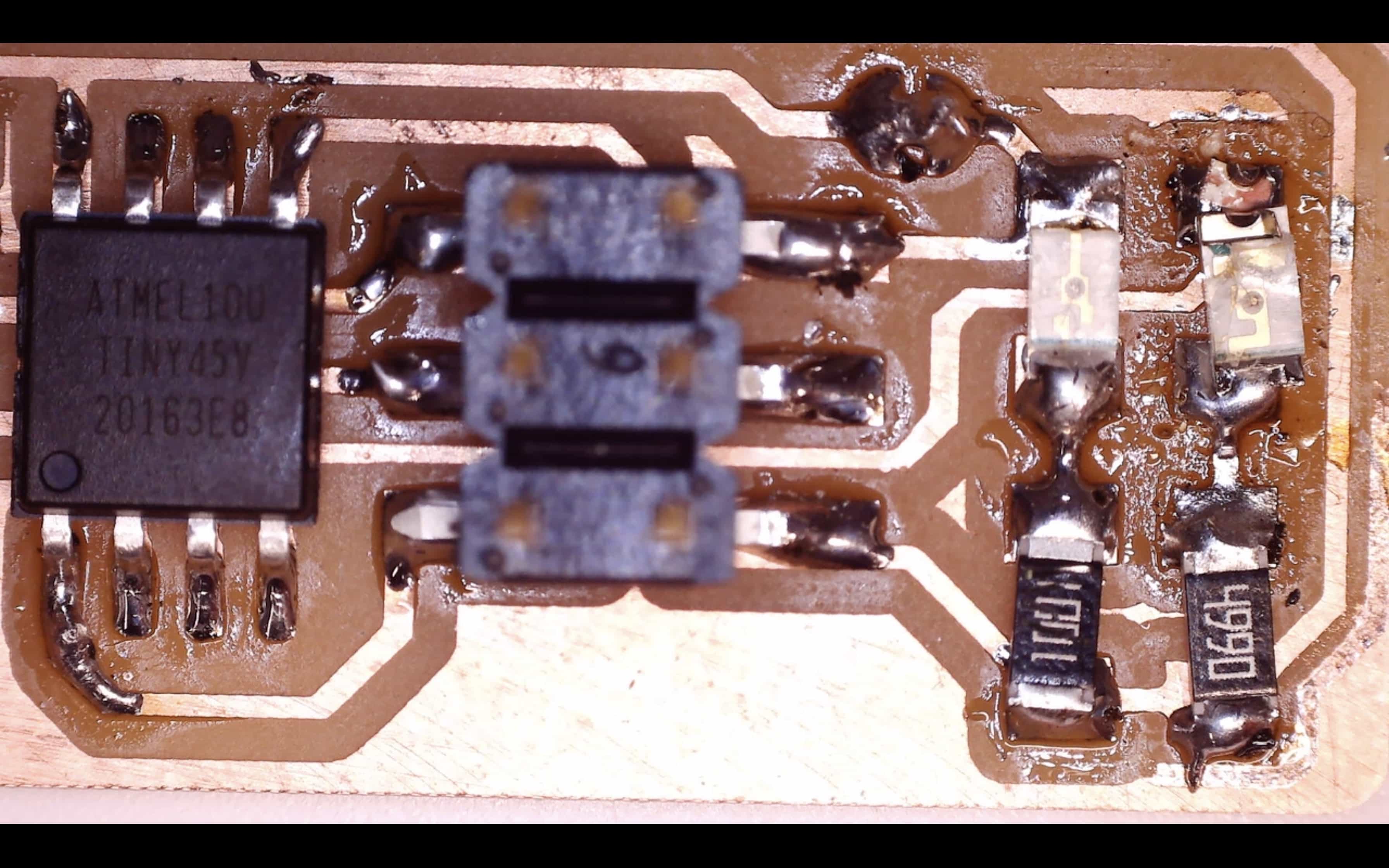
Ouch, they do not look good! I expected them to look a lot better. I will try again but first up, I'm going to test these to see if they do actually work in spite of poor aesthetics.
Soldering update - Week 13
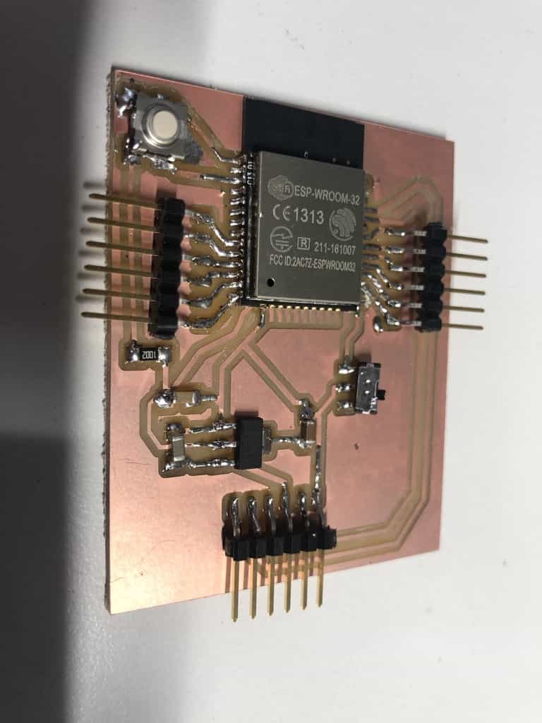
I'm pleased to say that my soldering has steadily improved during Fab Academy and here is my latest board. Its not perfect but its an improvement:
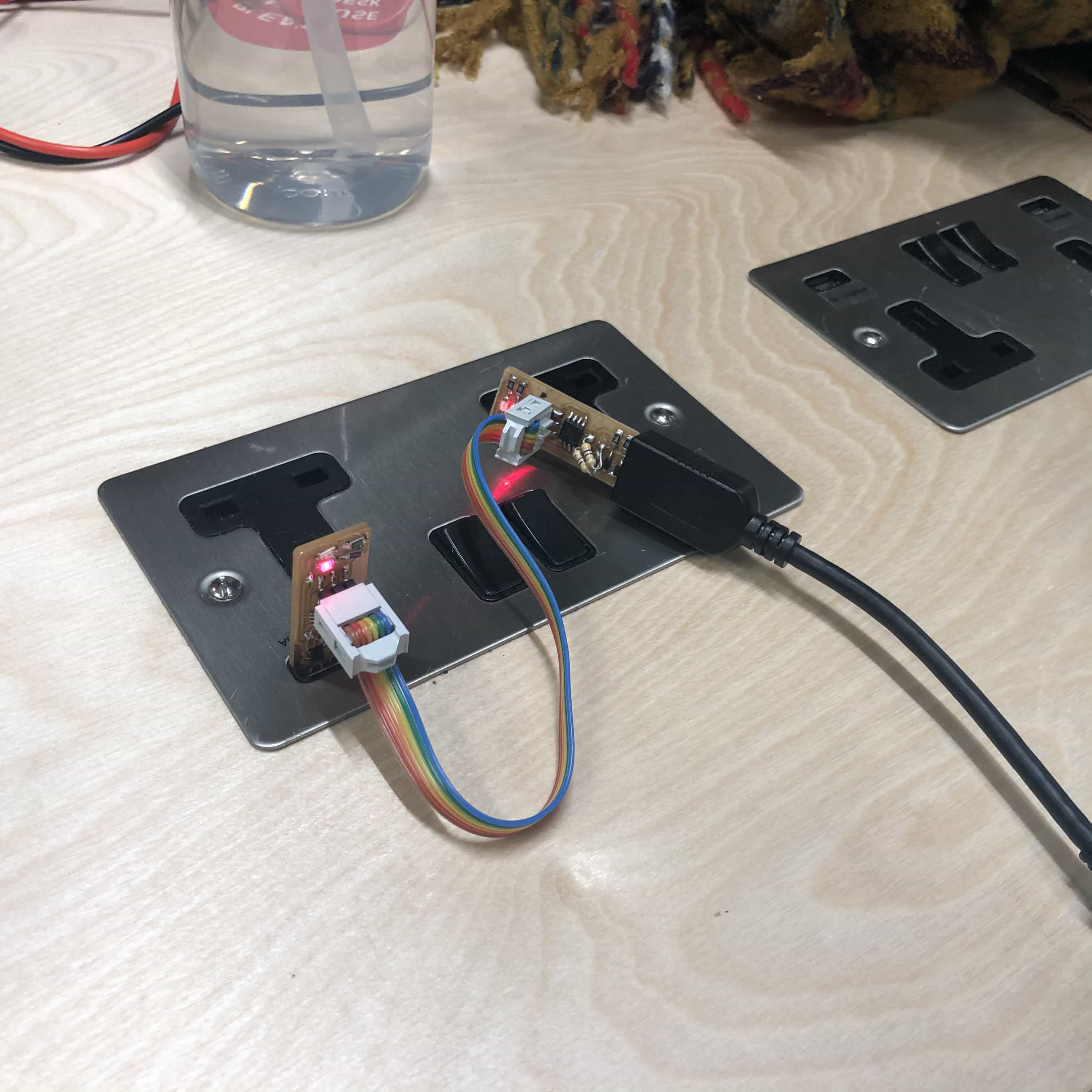
Testing the soldering
You can use the following workflow for testing: 1 - Visual inspection - Look for obvious issues such as solder crossing between 2 pads or wonky components 2 - Use the multimeter to test that the connections are clean. You can follow along each route and make sure the components are connected at each end 3 - Use the multimeter to test that there are not adjacent pads connected. Just tap on the two pads that are side by side and ensure there is no connection. Now its time to connect it to the programmer and see if we can turn our programmes into a programmer:
Using it as a programmer
We will be using the workflow outlined by Brian on the Fab Academy site:
For detailed workflow, use the link above. Basic outline is as follows:
1 - Get and build the firmware. Download the source code, extract the zip and run make.
2 - Edit the file called Makefile
3 - Plug into USB port. Use USB 2.0 (not 3.0) and use a short cable
4 - Connect the programmer to ISP header on your board
5 - Run make flash
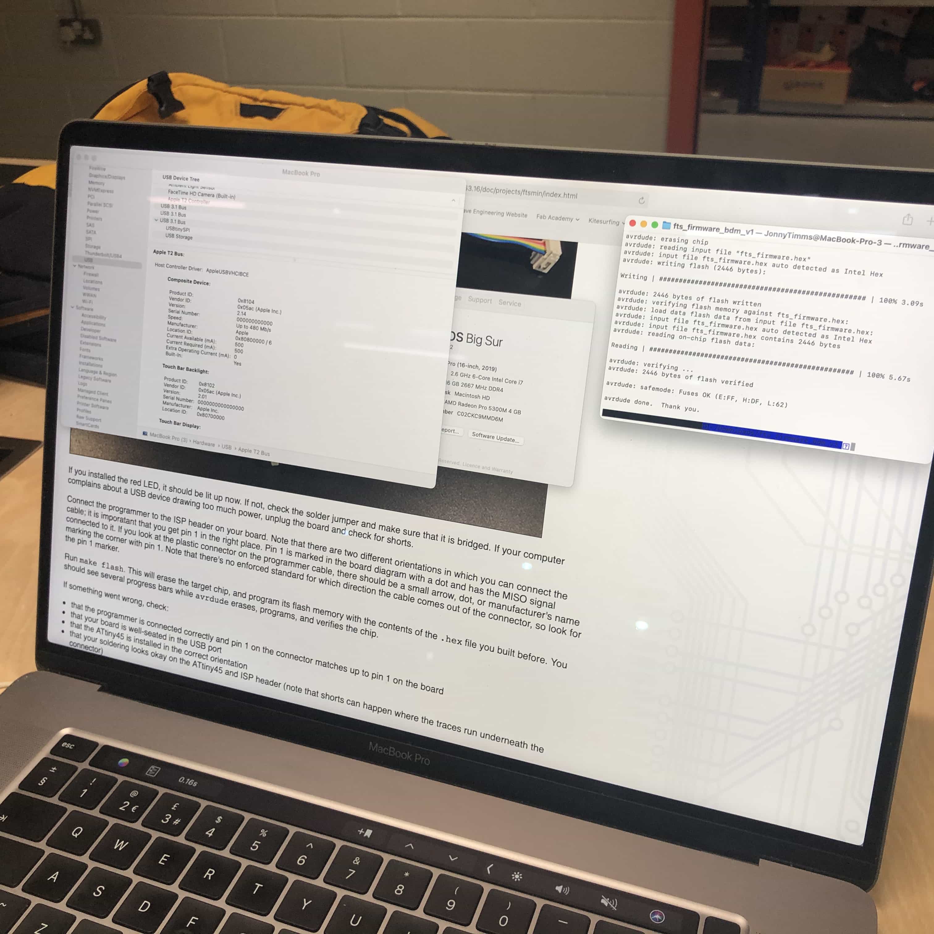
This was not easy!

Finally we have success! I have followed all the instructions in Brian's guide and successfully turned my programmee into a programmer.

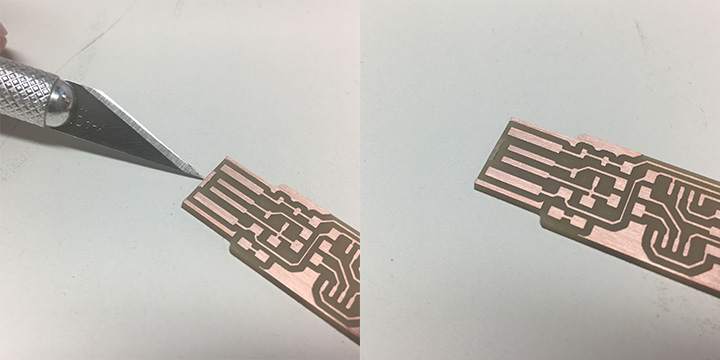
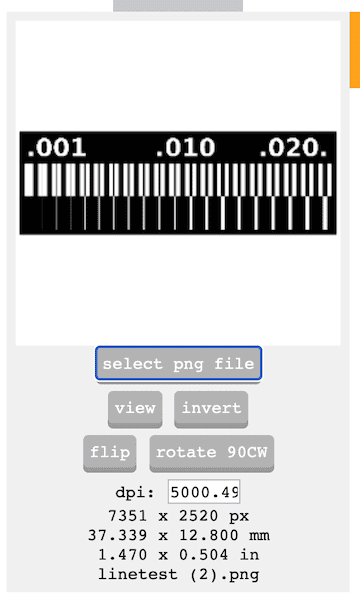
Group assignment - CNC characterisation with line test
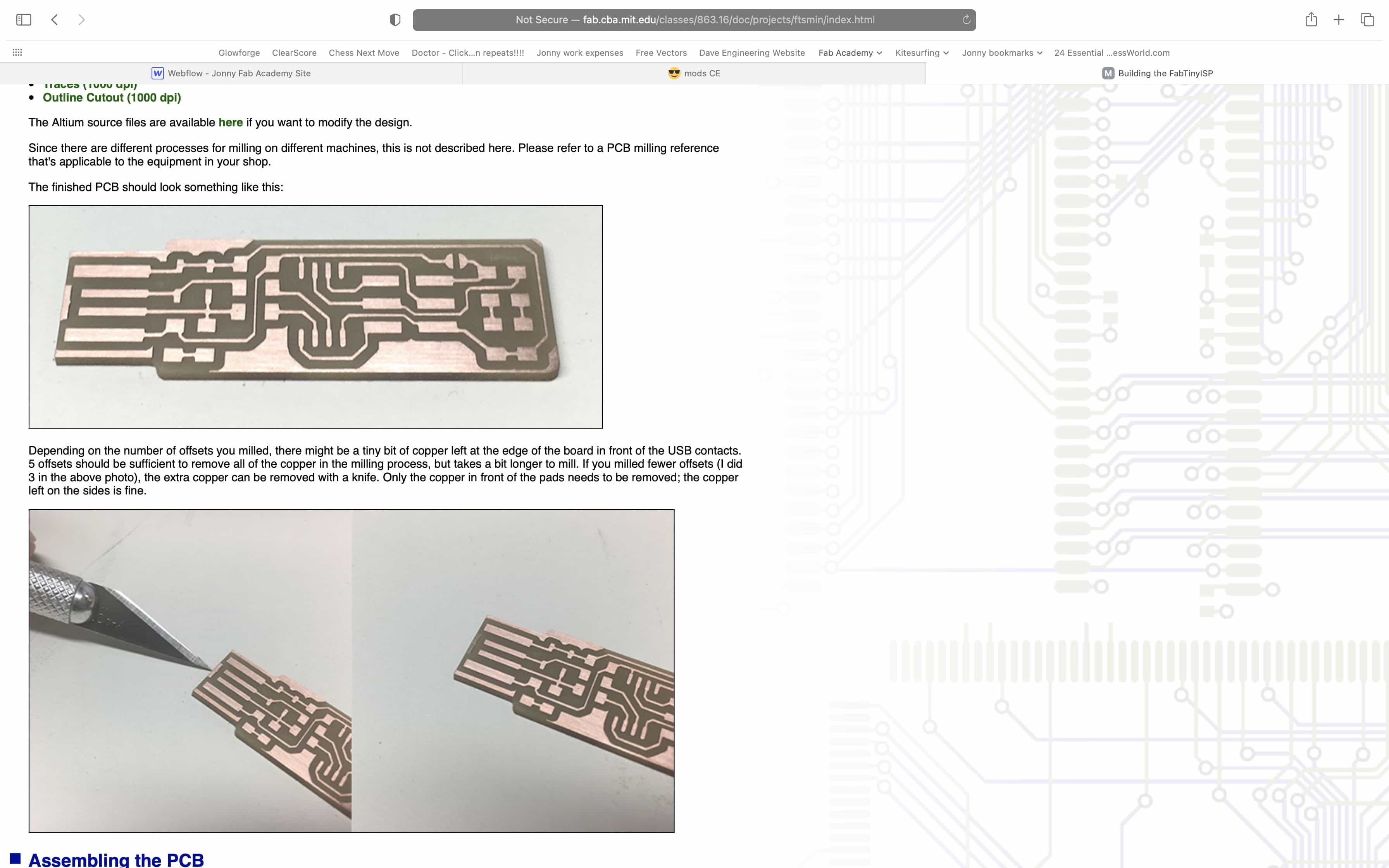
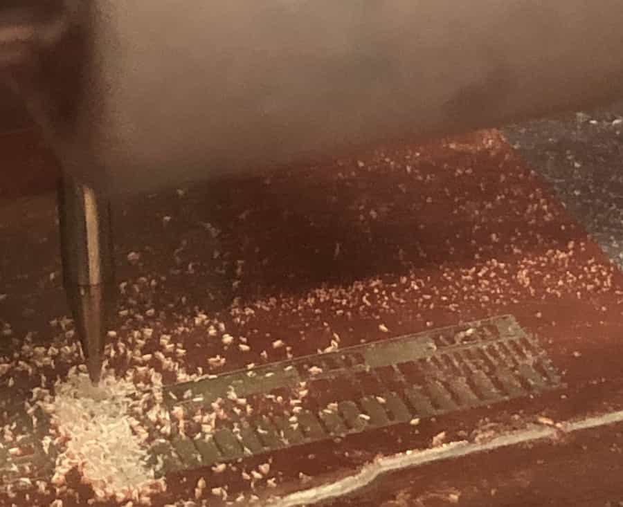
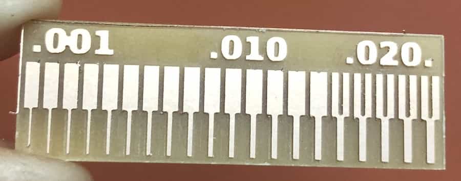
We shall be using the PNG file below to test how finely we can mill on our CNC machine. We've used all the processes documented above to load this PNG file into mods, generate our RML file, engrave the traces with the 0.4mm bit and then cut out the outline with the 0.8mm bit.
This was a fun group project and I'm pleased to say that our CNC machine performed well. As the final design below shows, we can make designs to an accuracy of .001 inch. This test proves that our 0.4mm endmill milled 0.4064mm in between. You can see in the photo that although the 0.001 inch width copper is still there, it is very weak and would not be considered reliable.
Group Assignment link

Back to homepage: