

Week 3 - Computer-controlled cutting
assignmentgroup assignment:
      characterize your lasercutter's focus, power, speed, rate,
         kerf, joint clearance and types
individual assignment:
      cut something on the vinylcutter
      design, lasercut, and document a parametricconstruction kit,
         accounting for the lasercutter kerf,
         which can be assembled in multiple ways,
         and for extra credit include elements that aren't flat
Characterise your lasercutter
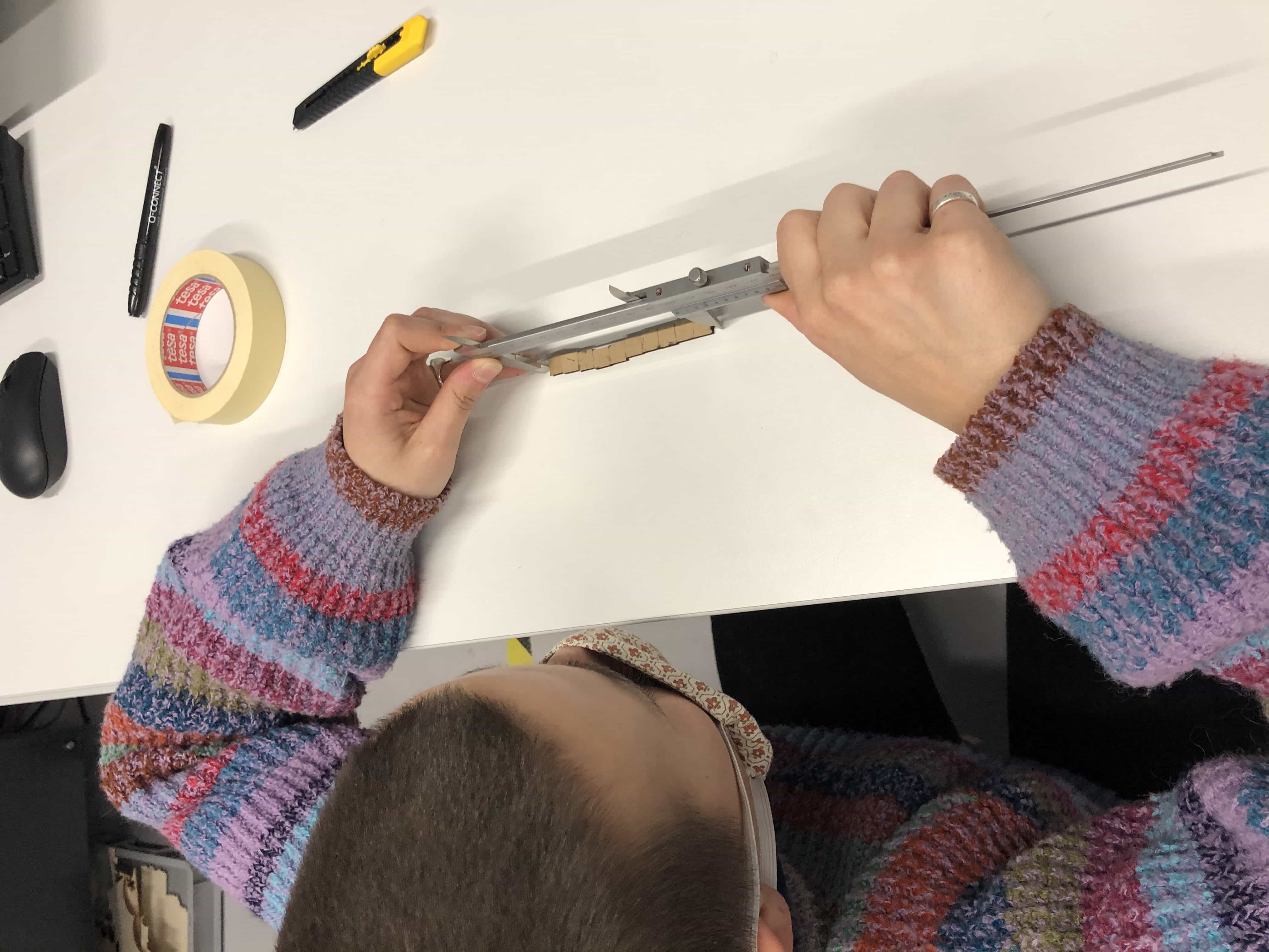
Our tutor Andrew had suggested that we print 10 squares, each 10x10mm, and measure the total length when lined up in a row. We did this, measured the loss to kerf and then did the exercise again with our kerf estimate added to the dimension of each square. We repeated the exercises until we could get a perfect 100mm total length. This is my classmate Katie measuring the 10 squares:
First test - Plywood
Test 1 - Inkscape size 10x10mm. Laser cut total length - 95mm Test 2 - Inkscape size 10.5 x 10.5. Laser cut total length - 102mm
MISTAKE - INKSCAPE RESIZED DIMENSIONS WHEN STROKE SIZE WAS ADJUSTED. WE NEED TO START AGAIN WITH 10X10MM. THIS IS A TOTALLY DIFFERENT APPROACH TO ILLUSTRATOR WHICH I NORMALLY USE. (ILLUSTRATOR TAKE THE DIMENSION FROM THE CENTER OF THE STROKE, AS OPPOSED TO THE EDGE OF THE STROKE)
Test 3 - Inkscape size 10x10mm.(Certain this time!) Laser cut total length 96.9mm Test 4 - Inkscape size 10.31x10.31. Laser cut total length 99.8mm Test 5 - Inkscape size 10.33x10.33. Laser cut total length 100mm. RESULT - Curf = 0.33mm
Second test - Acrylic
Test 6 - Inkscape size 10 x 10. Laser cut total length 98mm Test 7 - Inkscape size 10.2 x 10.2. Laser cut total length 100.6mm Test 7 - Inkscape size 10.14 x 10.14. Laser cut total length - 99.2 Test 8 - Inkscape size 10.175 x 10.175. Laser cut total length - 100.15mm Test 9 - Inkscape size 10.165 x 10.165. Laser cut total length - 100mm. RESULT - Curf = 0.165mm
Third test - Cardboard
Test 10 - Inkscape size 10 x 10. Laser cut total length - 97mm Test 11 - Inkscape size 10.3 x 10.3. Laser cut total length - 99.2 Test 12 - Inkscape size 10.4 x 10.4. Laser cut total length - 101.1 Test 12 - Inkscape size 10.35 x 10.35. Laser cut total length - 100.3 Test 13 - Inkscape size 10.33 x 10.33. Laser cut total length - 100.1 RESULT - Curf = 0.33mm (Its not a perfect 100mm but its good enough. cardboard is too variable as it warps and squashes when you try and measure it)
Cat design
I'm going to be using a design of a cat with the vinyl cutter and rather than design my own this time, I thought I'd find one online. Thanks to KJPARGETER who supplied this design on the freepik website:
Vinyl cutter
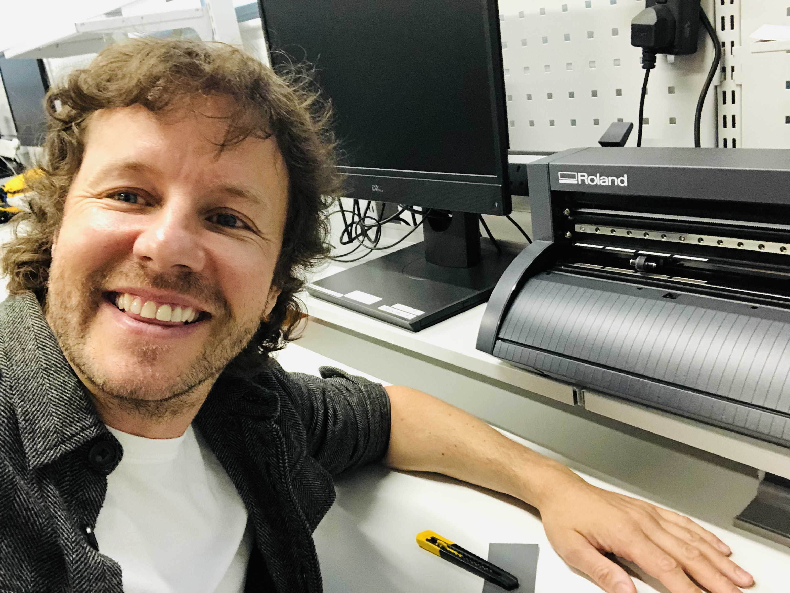
I've never used a vinyl cutter and so I was looking forward to this exercise. I absolutely loved the vinyl-cut circuit board that Neil showed in the lecture. Here is a photo of our vinyl cutter and me doing some work on it:
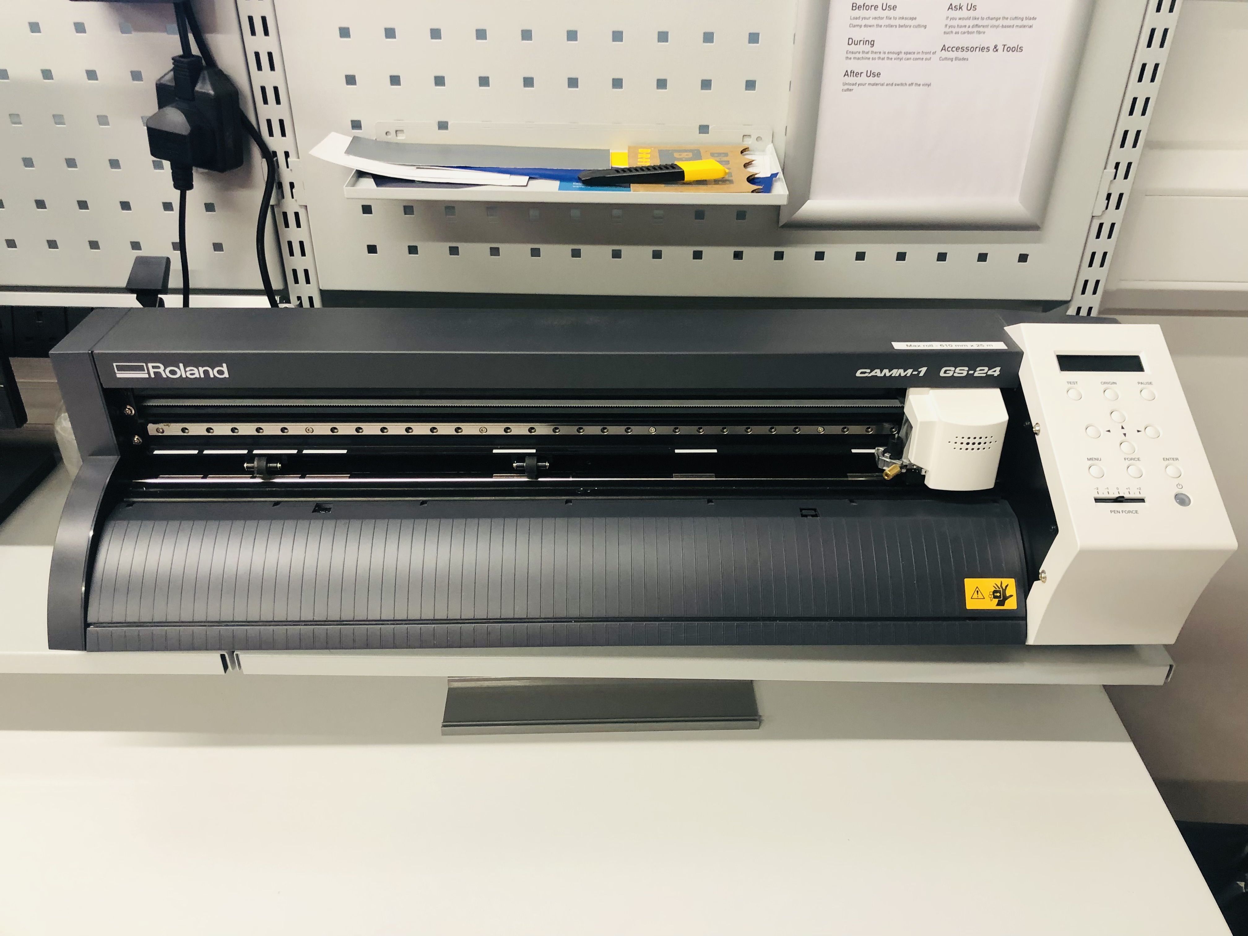
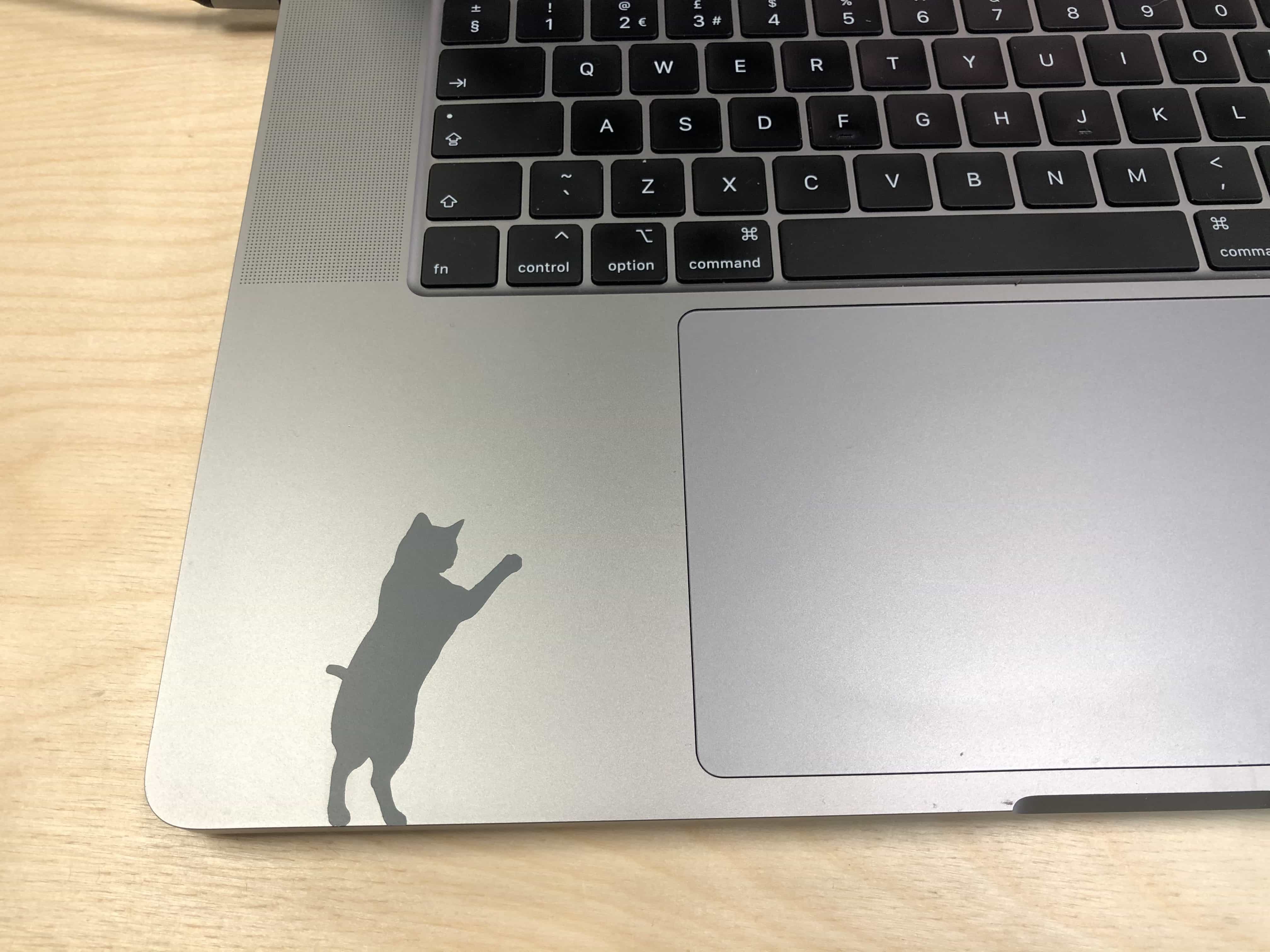
This is the workflow I used to print my design on our Fab Lab vinyl cutter which is a Roland GS-24: Setting up the Machine + Place your material in the machine + Using the rubber wheels, line them up with the edge of your vinyl, whilst keeping within thewhite markings + Line up the edge of the vinyl so it is straight with the lines on the curved part + Pull the leaver at the far left of the machine to lock the wheels in place + Now turn on the cutter, using the arrows on the machine select the correct type of size sheet you have ‘roll, sheet, *piece’ and press ‘entre’ + The machine will now measure your piece of vinyl Inkscape + Open file up in Inkscape + Check your file is the correct size + Go to File – document properties and write down the size of your piece of vinyl from the machine + Move your piece to the bottom left of the paper on the screen Printing + If you are needing to move the cutter use the arrows on the machine to change the origin – REMEMBER to hold down the ‘origin set’ button until it flashes + Now click on File – Print – printer preferences and click ‘get dimensions from the machine’ + Press ‘ok’ and then ‘print’ + Your job should now be printing I printed a design of a cat and stuck it to my laptop:
Parametic drawing
Let me start by saying I am excited to learn parametric modelling. I've been frustrated in the past when I have designed boxes or other shapes, only to find that my material is slightly bigger or smaller than the size I had assumed in my drawing. I've also found that the kerf on my home laser cutter (Glowforge) is larger than the kerf on the laser in my local maker lab (Trotec). In spite of these issues, I had never heard of parametric drawings until starting this assignment.
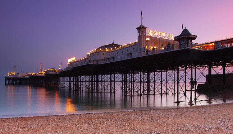
Brighton Pier
I decided to make a small model version of our local pier. Its our most city's most famous landmark.
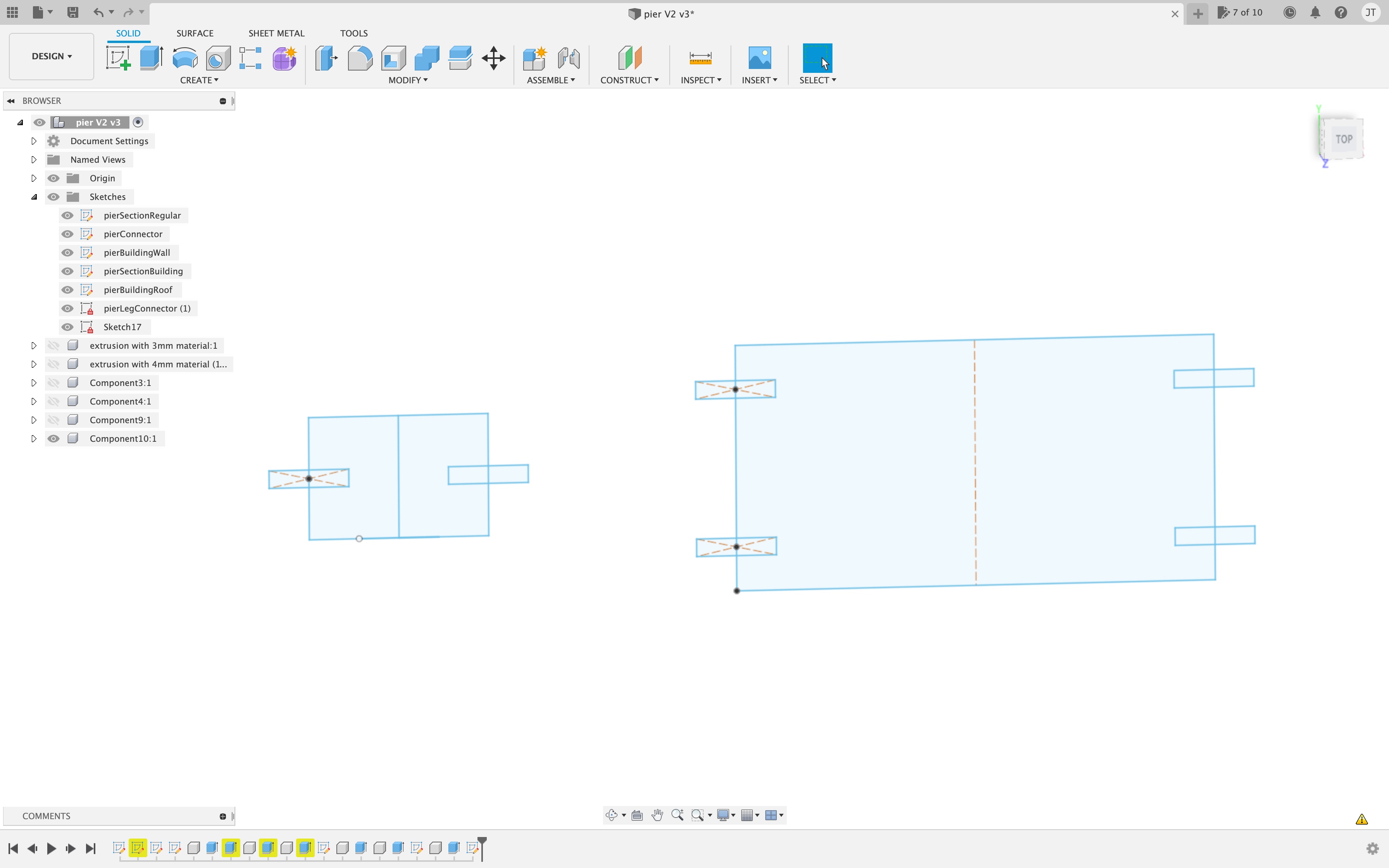
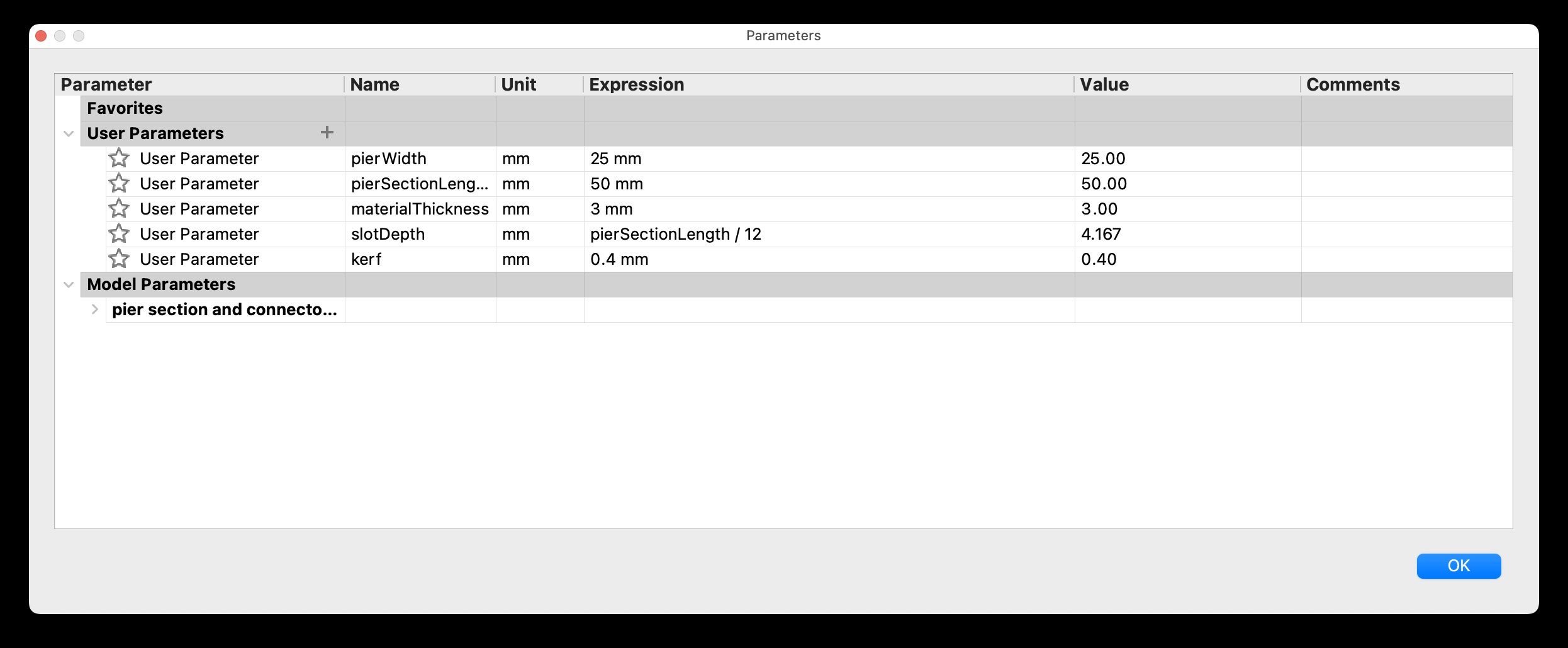
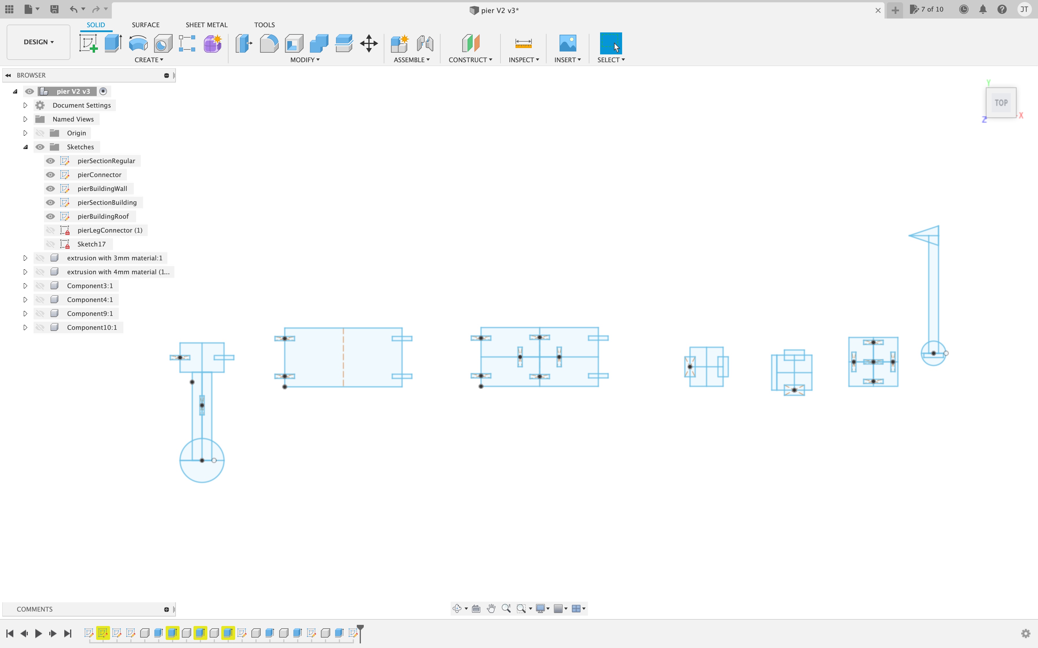
Our tutor Andrew did a tutorial on parametric drawings using Fusion 360. I followed the instructions and drew the parts needed to create some sections of pier and connectors to join them together. This is a connector on the left and a pier section on the right. You can also see all of the parameters that I set up, in this screenshot of the parameters window:
Cutting on cardboard
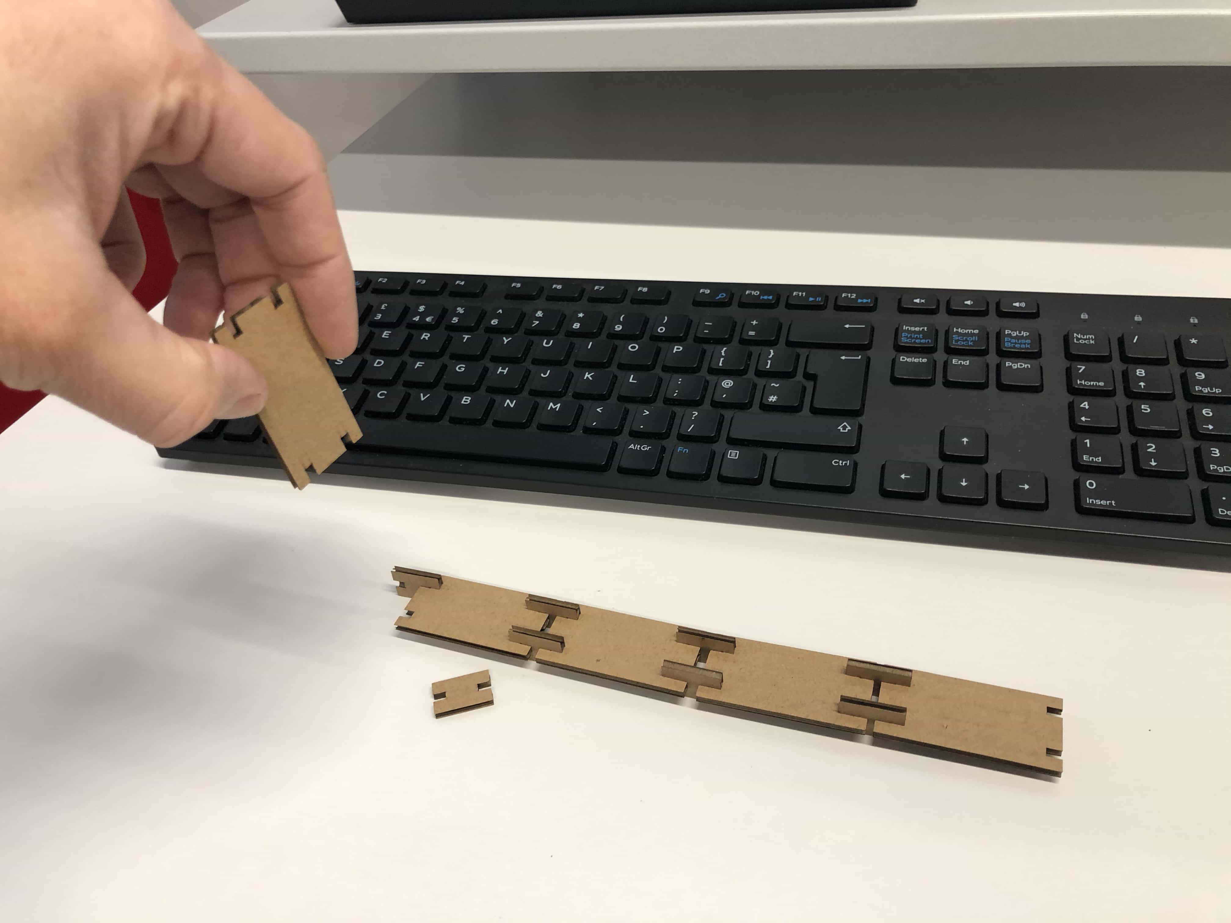
I've only been using laser cutters for the past 12 months. In that time I have never seen anyone use cardboard and I thought it sounded like an odd choice of material. I've pretty much only used plywood to date. I was really surprised what an awesome material cardboard is. In particular I liked the following: 1 - It cuts really quickly 2 - Readily available in a range of thicknesses 3 - Its strong enough to make working prototypes 4 - Its free and its absolutely frickin' everywhere! (Seriously, I just see cardboard everywhere now!) Here is my first cardboard print of the pier:
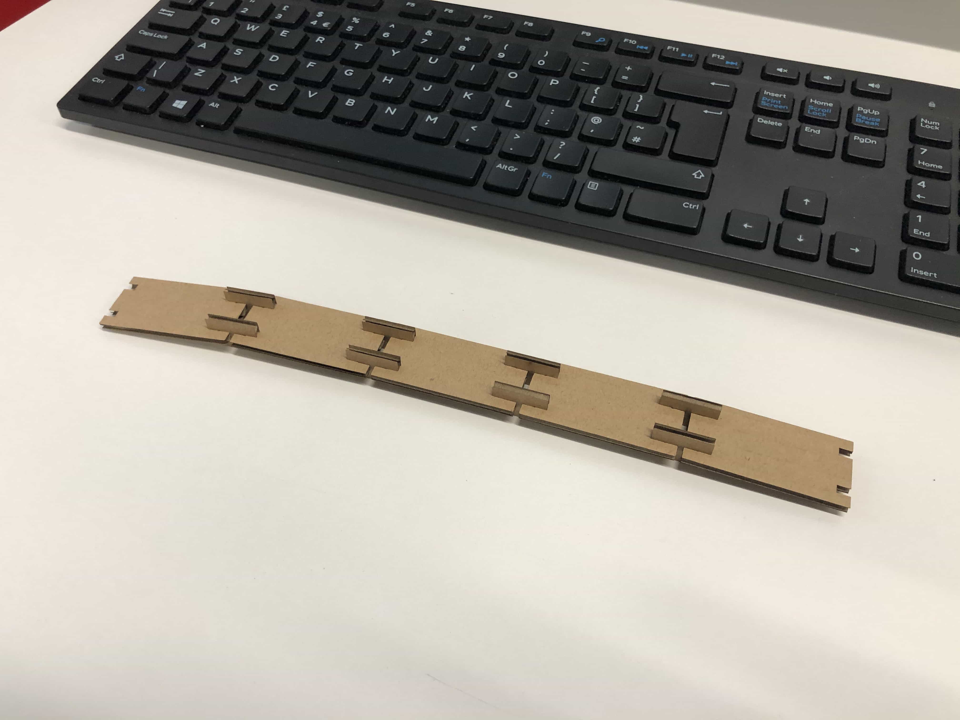
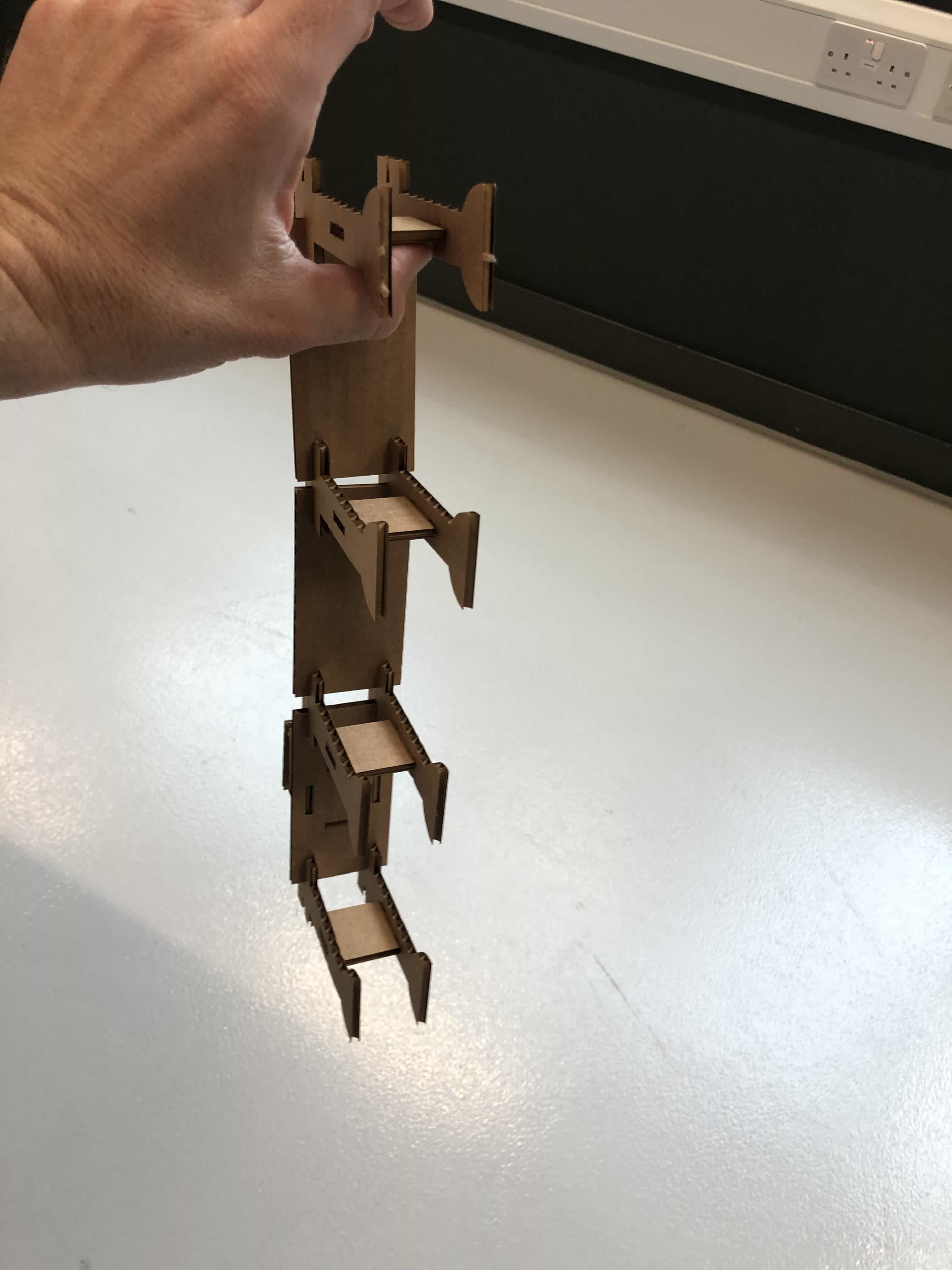
This printed out great. The connectors fitted nicely using the kerf measurement that we determined in our initial exercise above. The problem with this kerf measurement is that there was not enough bite for the pieces to hold together. If I lifted the piece at one end, everything would fall apart:
Our kerf measurement was based upon measuring pieces when placed end to end. In my model above, I actually need the pieces to be slightly smaller so that there is surplus material available to squash down and add the required bite. I changed the kerf from 0.33mm to 0.4mm and then everything fit together beautifully.
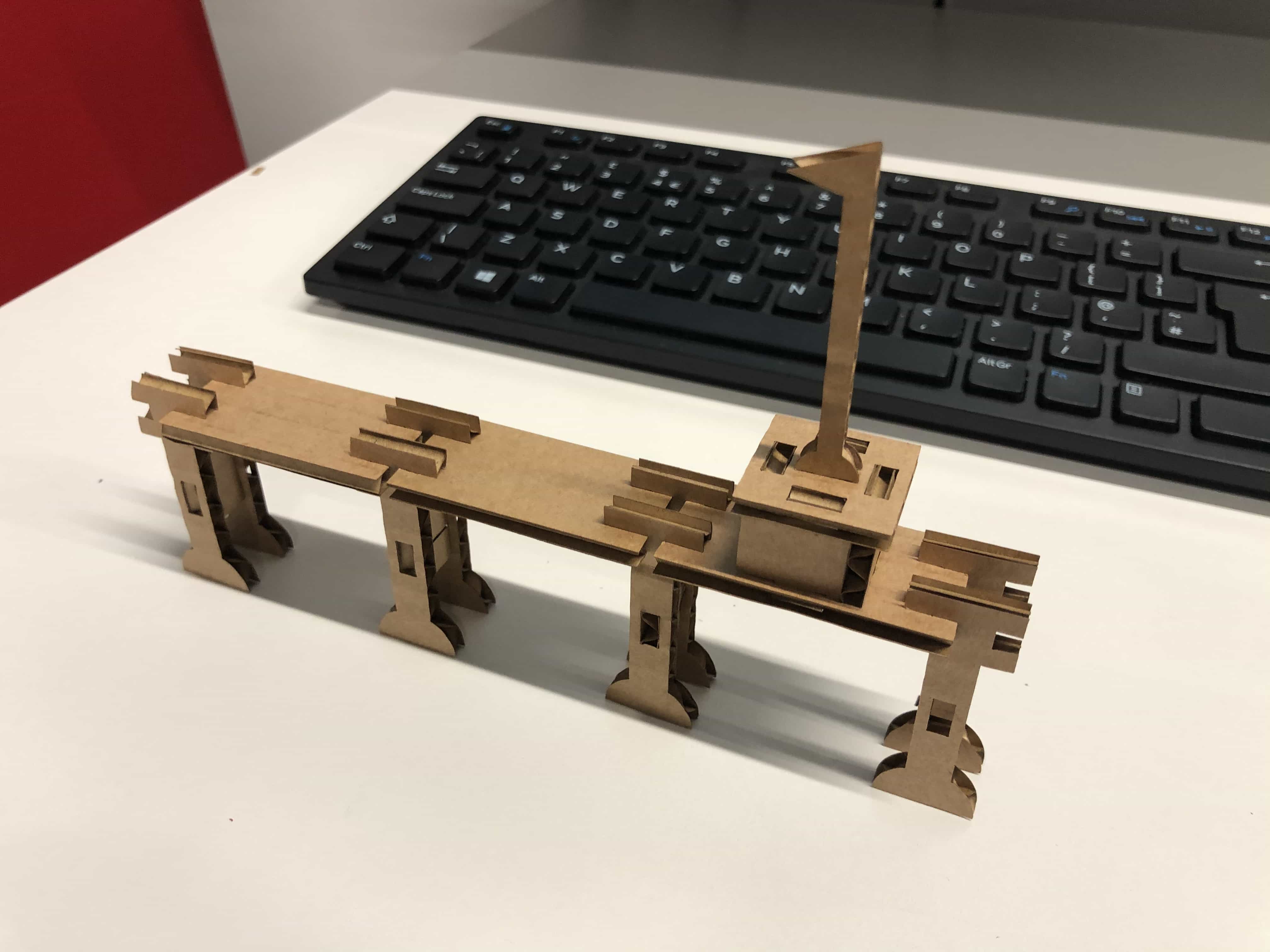
Now its time to some more detail to make it look slightly more like a pier! Here are some updated sketches:
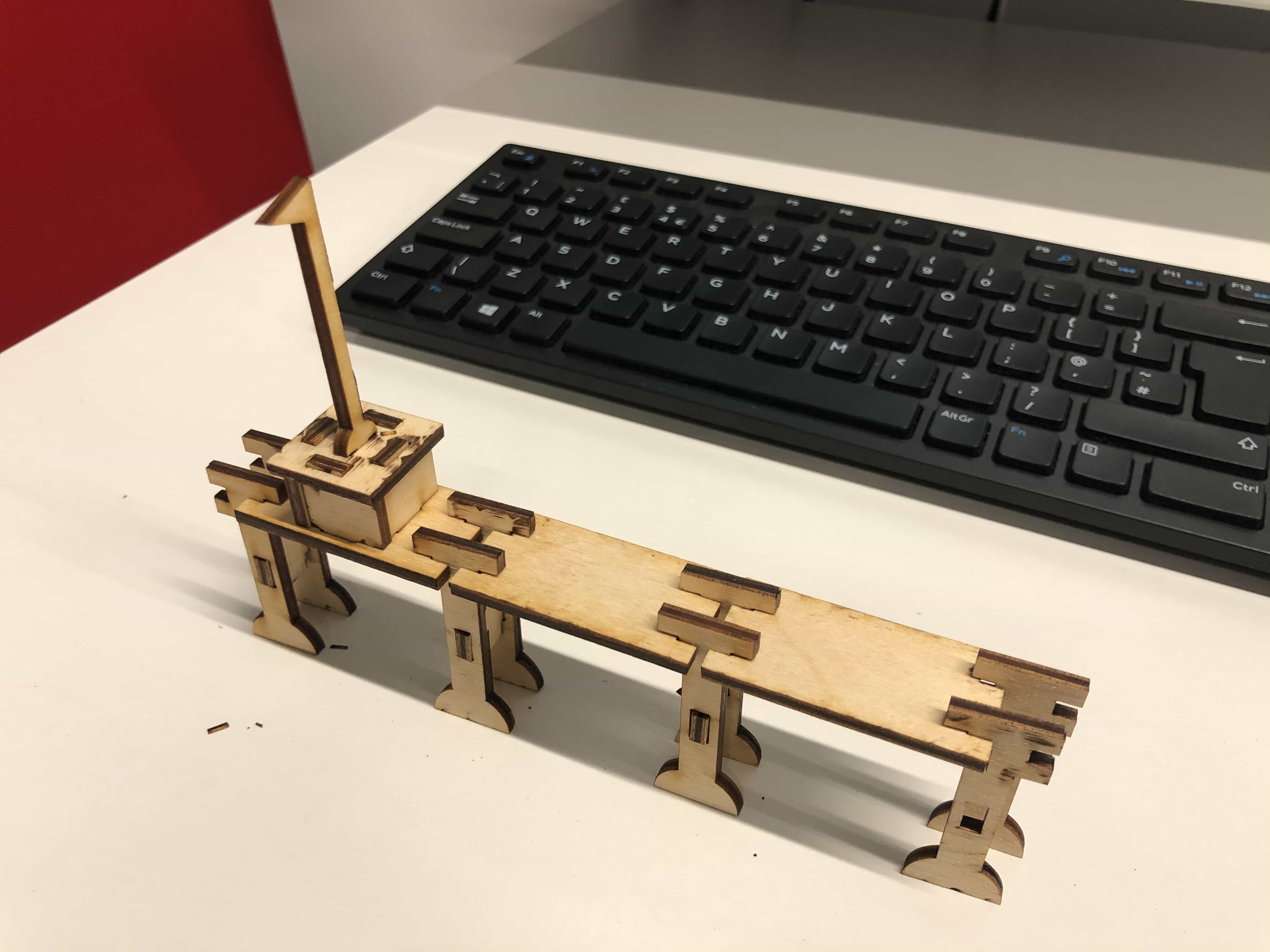
And here it is. You could argue that it looks more like an 8 legged golf course, but thats fine!
Now is the fun part. I'm going to double the length and width of the pier and see if everything scales up correctly. I'm pleased to say it almost worked perfectly. Everything scaled correctly apart from the flag. It was immediately obvious why the flag didn't scale up. I had set the height to be 50mm while it should have been pierWidth*2. I adjusted the formula and then laser-cut the new size:
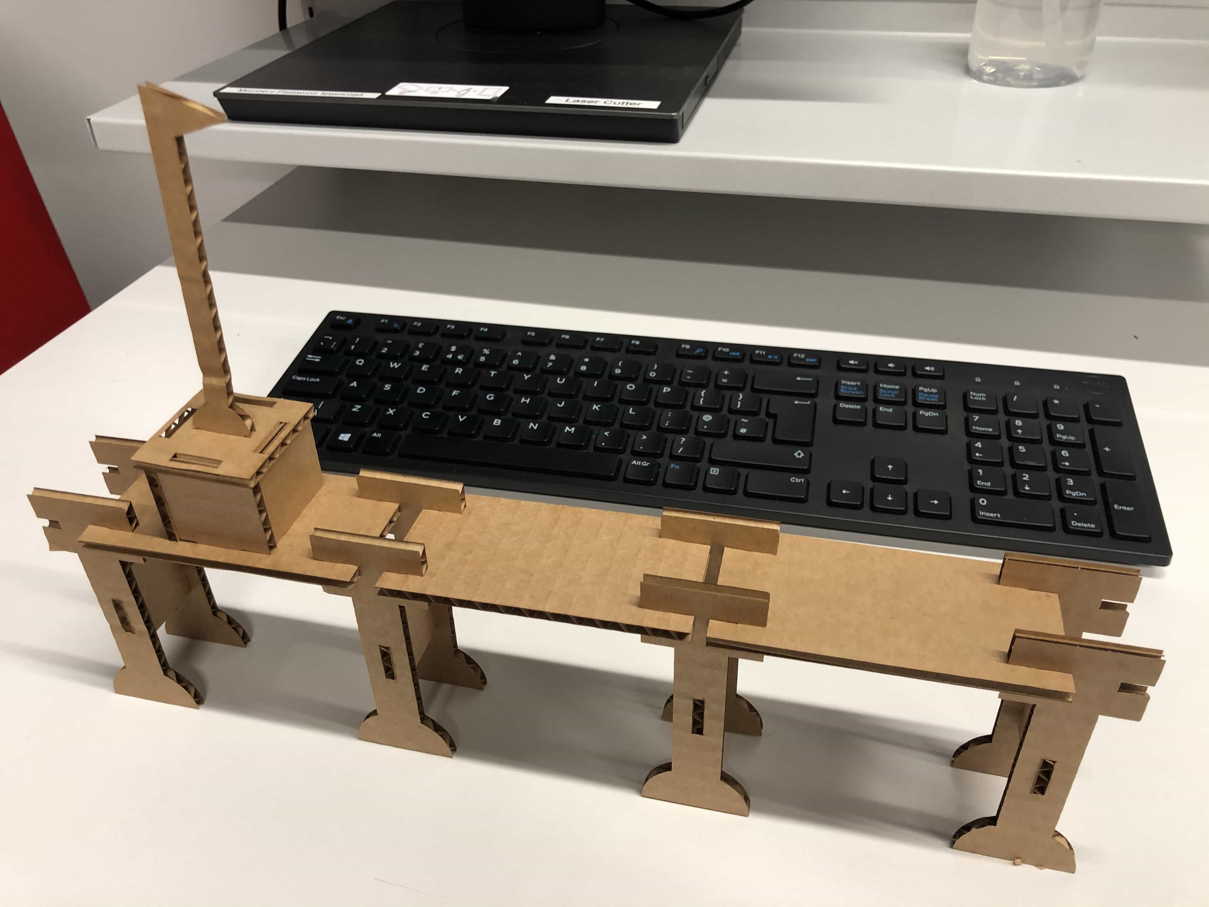
And here is a photo to illustrate that the model had sufficient bite to support itself:
Plywood model
My tutor Andrew suggested that I try the model with plywood and so I've made a small version using 3mm plywood. Its come out great:
Joints
I drew and printed the following joints on cardboard: 1 - Press-fit 2 - Chamfer 3 - Snap-fit 4 - Flexure 5 - Pinned
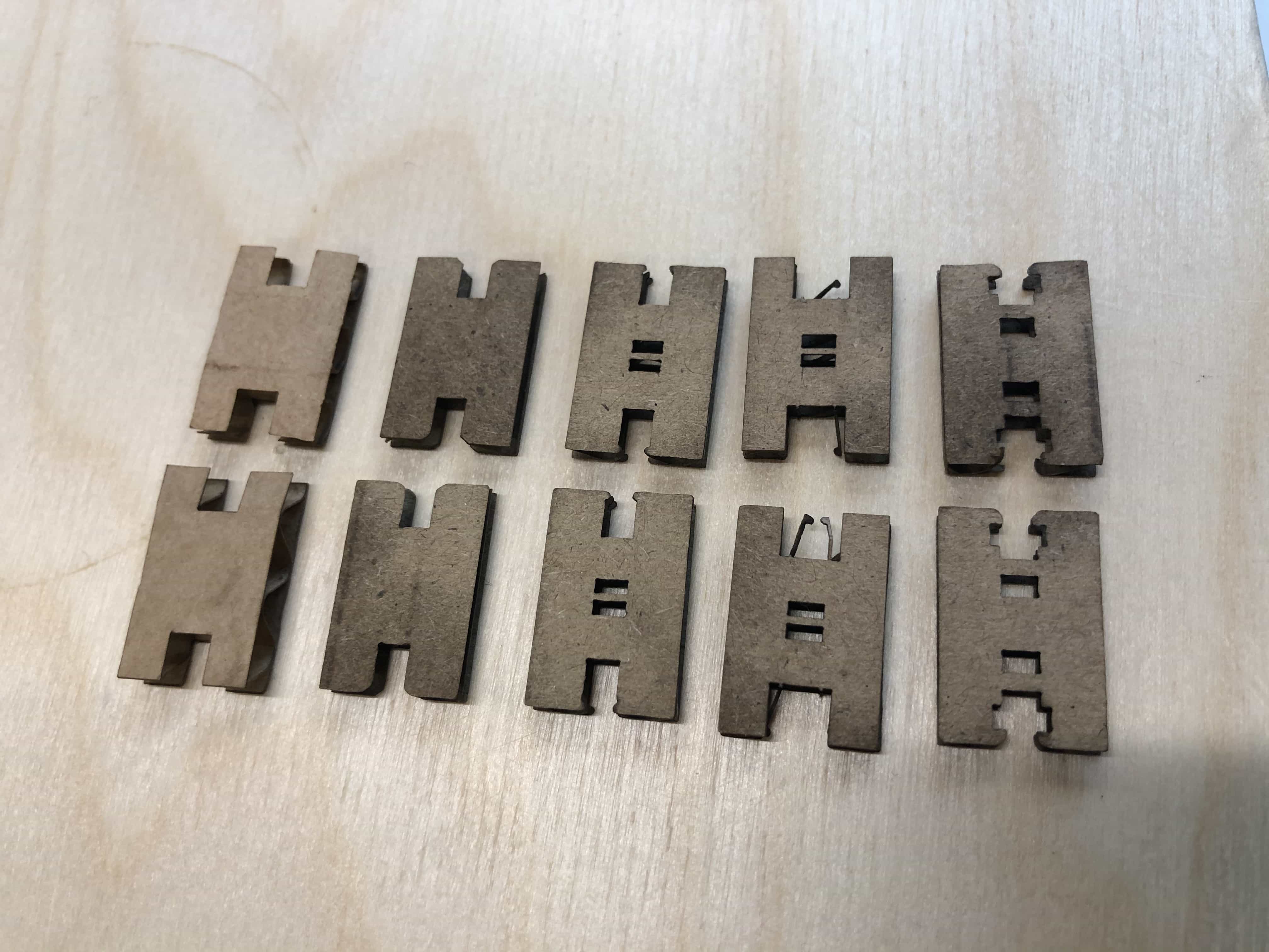
Of all the joints above, I thought I would try using the chamfer joint on my plywood model. It felt like a good choice because it relies upon getting the kerf measurement just right in order to hold together tightly. The other joints are fun but mechanism by which they hold in place allows you to be less accurate with the dimensions.
Files for download
Group Project Link
Week 3 - Computer-controlled cutting group assignment
Back to homepage: