3D Scanning and Printing

Week 5

Assignments

Group Assignment:
  • test the design rules for your 3D printer(s)
Individual Assignment :
  • Design and 3D print an object (small, few cm3, limited by printer time) that could not be made subtractively
  • 3D scan an object (and optionally print it)

Group assignment

For this week, Antti, Kenichi and I worked as a group to test the design rules for three different 3D printers existing in our FabLab. We used Test your 3D printer file (Figure 1), as the test design for all the 3D printers that were tested.

Figure 1. Test your 3D printer file

The file includes 21 tests. These cover all tests available on the FabAcademy, except for the infill test.

MakerBot Replicator 2

MakerBot Replicator 2 is a form of 3D printing technology with 100 microns resolution (as thin as a standard sheet of copy paper) which has the fastest speed in printing among tested three machines. Two most common materials for printing with the MakerBot printers are ABS (acrylonitrile butadiene styrene) and PLA (polylactic acid), but MakerBot Replicator 2 is optimized only for PLA filament.

Figure 2. MakerBot Replicator 2 in Fablab Oulu

Pros and cons of ABS are as following:

  • Good strength characteristics
  • Requiring good ventilation because it emits strong odors.
  • Requiring a heated build platform to avoid warping
While PLA has these following features:
  • Great surface quality.
  • Biodegradable
  • lack of impact strength.

In Fablab Oulu, we use PrusaSlicer software for this 3D printing machine which supports .stl, .obj and .thing . For printing, you just need to import files >> adjust and slice >> print.

Figure 3. In the middle of printing process (left) and removing the printed test from MakerBot Replicator 2 with a spatula (right)

Stratasys Fortus 380mc 3D Printer

The technology used in Stratasys Fortus is Fused Deposition Modeling (FDM), additive manufacturing process printing from bottom to top, layer-by-layer (each layer with each corresponding model material and support material).

Stratasys Fortus 380mc: Since this printer can work overnight and run automatically without supervision, it can be the best choice for printing objects with complex structure.

Figure 4. Our instructor, Behnaz, is explaining to us how to work with Stratasys Fortus 380mc 3D Printer

For preparation and sending printing order, we used GrabCAD and Control center. In GrabCAD, after importing .stl file, there was an unwanted part of support in the design. To remove that part, go to Support Settings->Support Style-> Sparse.

Figure 5. Removing unwanted support part of the design in GrabCad

When printing is over, you should wear a pair of gloves (beacuse of heat) and take the base sheet with the printed test. Then, try to remove the printed object smoothly from the base shit with a spatula. Finally, put the object in the tank containing sodium hydroxide, NaOH to soak which usually take 8 hours (at least).

Figure 6. Post-printing actions with Stratasys Fortus 380mc 3D Printer

FormLabs Form 3

Formlabs is based on Stereolithography (also known as optical fabrication, photo-solidification, or resin printing) technology. It is an additive manufacturing process where a laser beam builds up a model layer by layer from liquid polymer that hardens on contact with the laser light.

Figure 7. FormLabs Form 3 in Fablab Oulu

The software used for FormLabs is PreForm and supported files are .stl, .obj and the output file would be .form.

After printing, the model was first cleaned in Isopropyl alcohol, and then cured in 405 nm light.

Figure 8. Post-processing in Formlabs Form 3

3D printing results comparison

The following tables show the different features measured with the printed objects from three different 3D printers.

Figure 9.Printing results from different 3D printers

According to the resluts, MakerBot Replicator 2 was the best for overhangs and minimal distance, while Stratasys Fortus 380M sounded the best choice for rounded prints. FormLabs Form 3 had the best results in complex shapes (name/text) and in general, Stratasys Fortus 380M was the best among three printers.

Individual assignment

3D Design

As a part of this week assignment, we were supposed to design a 3D object an additive model that could not be made subtractively (by milling process, CNC, e.g.). First I came up with the idea of a hexapod stage with moving legs with spherical ends stuck in the upper stage holes and I statred with a threepod, but just skipped that due to lack of time. I will be back to this 3D design idea and develop it, later.

Figure 10. 3D design of a threepod as an additive model

So, I decided to go with a simple idea of a ball stuck in a cube. This object can not be made subtractively because the ball cannot come outside of the cube and therefore, needs to be designed by a 3D software and 3D printed such that removing the ball will require breaking the cube. I took the following steps to complete the design:

  • First, I drew a simple sketching of a 30mm by 30 mm square from Sketch > rectangle.

  • Then, exruded the square by going to Create > Extrude. You just need to click the surface and then drag it up and set it to 30 mm.
  • For making holes, I simply selected Solid->Create-> Hole and then, set the diameter (20 mm) and height (30 mm) of the cylinder as a hole. I repeated this for other faces of the cube to have 6 holes for the whole faces.
  • After that, from Modify > Fillet, I added 1 mm fillet (round) to the edges of the cube.
  • Finally, I drew an sphere from Create > Sphere and firstly, set the sphere diameter to 24 mm to be larger than the holes sizes to ensure that it will get stuck inside the cube. However, at the time of printing and as the final check with our instructor Mikko, I decreased the diameter to 21 mm because with 24 mm, it had some extra cross sections with the inner faces of the cube. Then, I moved it smoothly inside the cube. Check the ball and cube from different views to make sure that there is no contact between them.

Figure 11. The full process of making a 3D design with a moving ball stuck in a cube

3D Printing

For 3D printing, I used Stratasys Fortus 380mc 3D PrinterStratasys Fortus 380mc 3D Printer which was introduced earlier.

To prepare the file and send the printing order, I used GrabCad. The printing process was quite straightforward. First, I imported my .stl file from Add Models.

Figure 12. Importing files in GrabCad

Then, from Model settings, choose my desired Part Fill Style. As Gleb advised me, I did not choose Solid.

Figure 13. Choosing Part Fill Style

From Support Settings->Support Style, I firstly chose SMART, but after slicing, I had to change it.

Figure 14. Choosing Support Style

Then, I went to Slice preview which would take a bit of time and noticed there are extra support material on the design. So, based on our last experience and as Behnaz suggested us, I changed the Support Style from SMART to Sparce.

Figure 15. Slicing preview in GrabCad

At the final step, I decided to enlarge the size of my model, so I went to Scale and change the dimenions from 30 mm to 50 mm.

Figure 16. Scaling in GrabCad

Finally, I sent the Print order. Then, I wore a pair of gloves to place a base sheet on top of the 3d printer's work base. Next, I closed the door and waited for a while until the sheet get heated and flattened. Then, I adjusted the placement of the printing part through the 3D printer's touch screen GUI. Finally, I pressed Play on the Printer's GUI.

Figure 17. GUI in Stratasys Fortus 380mc 3D Printer

After three hours, the printing was over and I took the sheet out of the machine by using a pair of gloves. Then, I tried to remove the printed object smoothly with a spatula.

Figure 18. Printed object with support material obtained from Stratasys Fortus 380mc 3D Printer

Next, as the only step of post-procesing for this machine, I put the object in the NaOH tank to be soaked for 8 hours.

Figure 19. Soaking the printed object in the NaOH tank

After 8 hours, the object is ready!

Figure 20. Final printed object with Stratasys Fortus 380mc 3D Printer

3D Scanning

For 3D scanning, firstly, I decided scan a blue bird statue by Makerbot Digitizer, but Mikko warned me it would not be succesful because the object is shiny. He recommended me to use Photogrammetry which has a simple function of recaping several pictures taken from different angles by your camera or phone. I started to take pictures with my cell phone and put the object on a catalogue to ensure of the random pattern of the base sheet. But I was not happy with the angles and accuracy of each move I made with the base sheet.

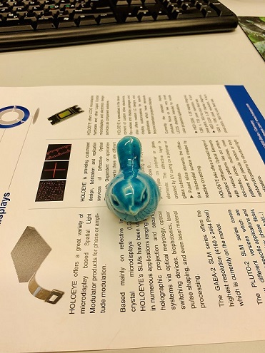
Figure 21. Taking photos of the object with cell phone for Photogrammetry

To dicrease the risk of scanning a shiny object, I decided to change it to a cat mosaic Barcino statue (Gaudi Style) which was a souvenir from beautiful Barcelona.

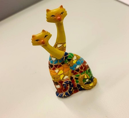
Figure 22. A cat mosaic Barcino statue (Gaudi Style) finally selected for Photogrammetry

So, I discussed the problem with Mikko and he suggested me to use a gimbal called DJI Osmo which provides a steady position and angle of the camera that I needed for Photogrammetry. I attached my phone to the device and downloaded the related app which is called DJI Mimo. Then, to optimize the angle of the camera, I put the object on a box to elavate it and then, fix it to the base which was a catalogue.

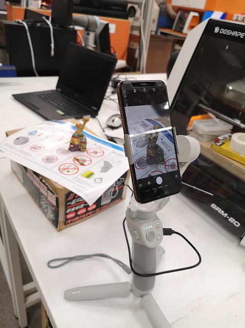
Figure 23. Taking photos from the object with a gimble (DJI Osmo) for Photogrammetry

Next, I started shooting and after each photo, I moved the base slightly and took a new photo. Finally, I turned the object all around and took 59 photos of it form different sides.

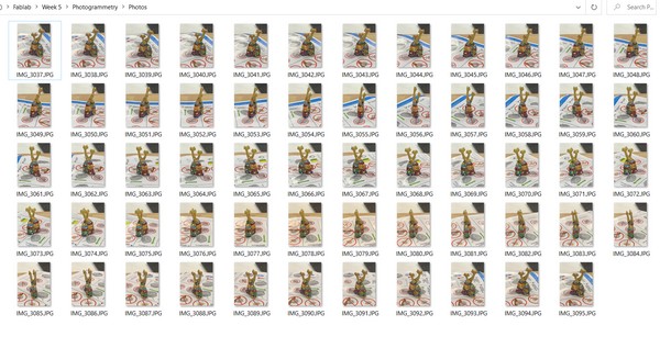
Figure 24. Taking photos from the object with a gimble (DJI Osmo) for Photogrammetry

After finishing shooting, I tried to recap the photos and as it was recommended in the instructions, I started to use Colmap for Reconstructing geometry from photos. I followed this turorial as following:

  • Launch Colmap using Colmap.bat
  • From the top menu, choose Reconstruction –> Automatic reconstruction.
  • Set the Workspace folder, this folder will be used for storing reconstruction calculations and the output mesh. Create another directory next to the Photos folder for this purpose.
  • Set the Image folder the Photos folder containing all your pictures.
  • You can leave the Vocabulary tree empty, alternatively, you can download and use one from this download page
  • . I downloaded the marked file in the figure 23.
  • Keep the Data type as Individual images or change it to Video frames if you created the pictures from video
  • Change the quality to Medium. You can try High quality, but in our experience, Colmap crashes very often with this setting
  • Leave other settings with default values and hit Run.
  • This process may take anywhere from 5 minutes to seemingly eternity depending on the number of photos and specs of your PC.

When Colmap finishes the reconstruction, you’ll be presented with a reconstructed view of the scene and estimated positions of the camera.

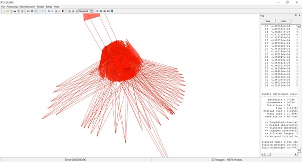
Figure 25. Colmap set-up and finished view of the reconstructed scene

But there were no fused.ply and Meshed.ply files generated in the workspace folder as explained in tutorial. So, I decided to try Autodesk Recap Photos. It has very simple instructions to use. Just launch the software and from Dashboard, go to Create 3D->Object and choose yuor photo. Then, choose Add photos and finally, Create.

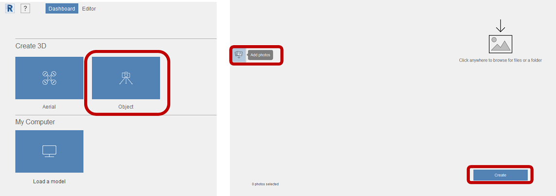
Figure 26. Autodesk Recap Photos interface

But you must be patient since it is cloud-base and it might be some oher works on the queue. For several hours, I only saw "Waiting in queue... 1%" (Figure 27).

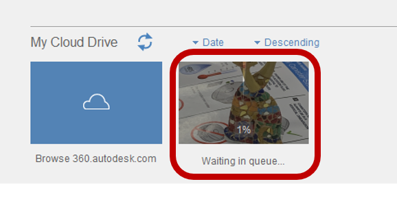
Figure 27. "Waiting in queue... 1%" for several hours in Autodesk Recap Photos

Finally, the 3D scanned object was ready although there were some extra parts needed to be removed.

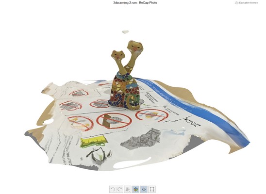
Figure 28. 3D scanned object in Autodesk Recap Photos

I simply used the edit bar from left side by going to Slice and Fill and adjusting the axis to be sliced.

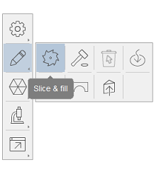
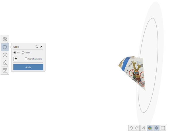
Figure 29. Removing the background in Autodesk Recap Photos

At the end, I just remained the object without any background.

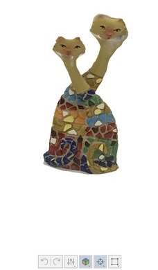
Figure 30. Final result: Processed 3D scanned object in Autodesk Recap Photos

Files

Reflection

During this week, I got familiarized with three different 3D printers we have in Fablab Oulu and their advantages over each other that was very interesting. Also, I learned about some 3D scanners and their functionality through the inclusive explanations of our local instructor, Behnaz. Then, I designed a 3D model to print it from a 3D printer and also, 3D scanned an object with Photogrammetry, all for the first time.

Mona Peyvasteh

Fab Academy 2021

Diary of my journey to the world of Digital Fabrication