Week7
Computer controlled machining
Go to:Group assignment Individual assignment
Group assignment
Test runout, alignment, speeds, feeds, and toolpaths for your machinedocument your work (in a group or individually)
For this week's assignment, since our workshop here in Cuenca is in re-construction, I have kindly been received in FABLAB EU in Madrid by Alberto. There we met with Lorena and also visited Mauro´s workshop.

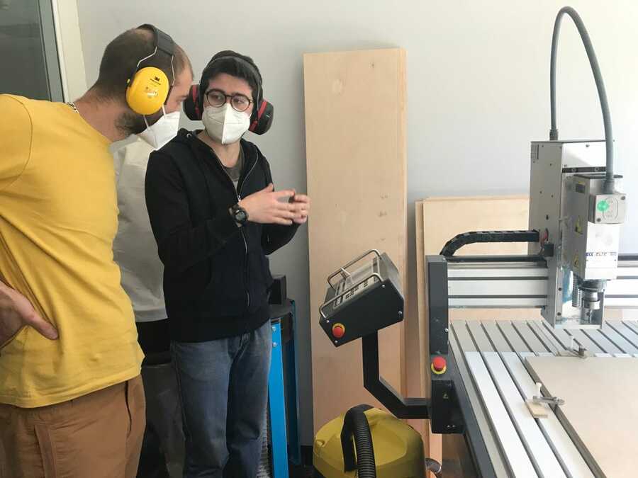
There, Alberto introduced us to the FR 210 cnc machine from Alarsis, it has a 2000 mm x 1000mm working area, has its own control unit and there, we prepare the jobs with rhinocam and load it from a usb drive.

He explained the security measures established in the lab. Wear ears and eyes protection, no hanging clothes, hairs or jewelery. Where to stand when the machine is functioning and where the emergency stops are.


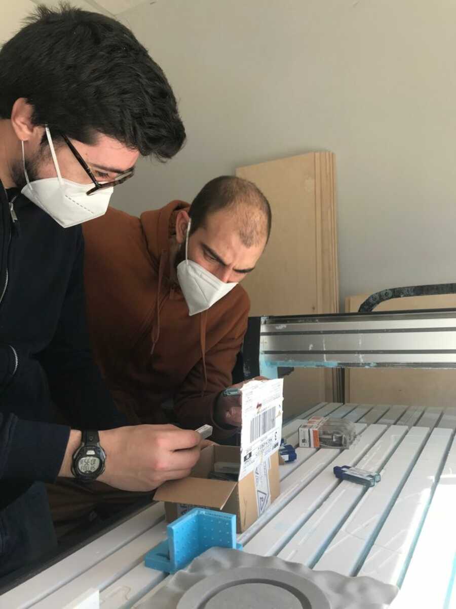
We saw some basics of the machine like how to change the milling bits.


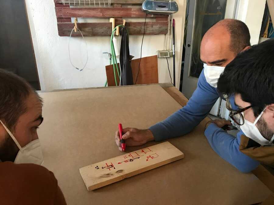
And how to use the controls to manipulate the axes and set the origines.


Mount and secure the material with clamps...

After doing a few dimension tests.


And speed and feed tests with a universal milling bit (6mm) and a special milling bit for laminated wood and MDF.


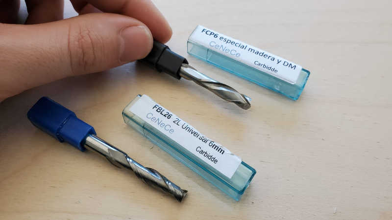
We determined that the best performance was at 12000 rpm, a pass of 2.5mm depth at a feed speed of 1500mm/min using the special milling bit for laminated wood and MDF.
Here is some of the set up in Rhinocam where we set the material thickness (15mm), type of process used (cut in or out of the path), the feed and speed, depth of passes and select the type of milling bit used.


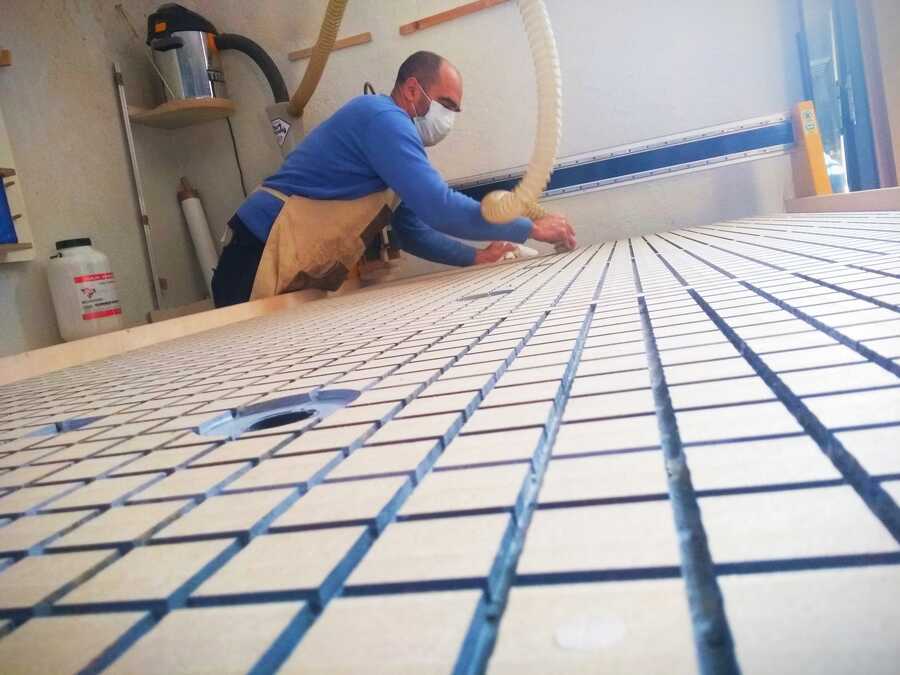
In Mauro's workshop, we got to see how he set up and prepared his vacuum-workholding table, the different milling bit he uses to do that. We also talked about adding dog bones and the different types of processes that can be used in order to get better results.
Straight x1 flute milling bit and 30mm flatning


Go to:Group assignment Individual assignment
Individual assignment
Make (design+mill+assemble) something big
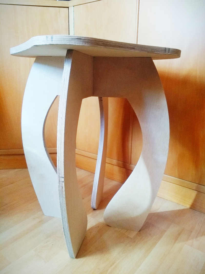
For the design, since it's the first time using this machine and I am also traveling, I decided to make a stool. I designed it in fusion360 adding parameters to allow for material thickness adjustments.


I used the inspect tool to make sure there was no overlapping parts in the assembly.

Exported the DXF files to have an .SVG file.

Using the parameters we determined during the group assignment, the design was set up in rhinocam and saved into the pendrive.


...secure the material, set the origins and sent the job.


Cleaning up and assembly...


While I was putting it together, I noticed a few things that could probably be avoided next time.
For example, the milling bit burns the sides when processing the tabs.

I may also have made the joints a little on the tight side.

And ofcourse I also created some nice additional features...

In the end it came out well enough and functional.


Learning outcomes
Demonstrate 2D design development for CNC productionDescribe workflows for CNC production
Have you?
Linked to the group assignment pageDocumented how you designed your object (something big)Documented how you made your CAM-toolpathDocumented how you made something BIG (setting up the machine, using fixings, testing joints, adjusting feeds and speeds, depth of cut etc.)Described problems and how you fixed themIncluded your design files and ‘hero shot’ photos of final object
Key Learnings
- Always run a test cut on scrap material before cutting your final piece — large format CNC mistakes are expensive in both time and material. A 5 minute test cut on a scrap piece of the same material confirms your feeds, speeds and depth of cut before committing to the final job.
- Fixturing is as important as the toolpath — a poorly fixed workpiece will move during cutting and ruin the job. Use clamps, screws or double-sided tape depending on the material and make sure fixturing points don't interfere with the toolpath before starting.
- Check your toolpath simulation carefully before running — Fusion 360's simulation mode shows exactly where the tool will travel including any air cuts, plunges and retracts. Watch the full simulation before sending the job to the machine.
- Climb milling vs conventional milling affects surface finish — climb milling generally produces a better surface finish on wood but can cause tearout on some grain directions. Conventional milling is safer on a less rigid machine. Test both on scrap if surface finish matters.
- Leave tabs on parts that will become fully cut out — without tabs, a fully cut part lifts off the bed mid-job and gets caught by the spinning bit. Add tabs in Fusion 360 and cut them manually after the job completes.
- Feed rate and spindle speed must be matched to the bit diameter and material — too fast a feed rate with too slow a spindle speed causes the bit to rub rather than cut, generating heat and burning the material. Use a feeds and speeds calculator for each new material and bit combination.
- Zero your Z axis carefully — especially on uneven material — wood can vary in thickness across a sheet. Touch off the Z axis at multiple points across the workpiece and if your software supports it use a height map for large jobs on uneven material.
Related weeks
Week 2 - Computer-aided design —
Fusion 360 CAD models designed in Week 2 used to generate toolpaths for CNC machining this week.
Week 3 - Computer controlled cutting —
Computer controlled cutting skills from Week 3 extended to large-format CNC machining documented here.
Week 5 - 3D scanning and printing —
The 3D printed brain model from Week 5 was used alongside CNC milled parts in the final assembly.
Week 9 - Mechanical design / Machine design —
CNC machining techniques from this week used to produce structural parts for the machine building project.
Week 11 - Molding and casting —
Machinable wax mold master for the brain cast was produced using the CNC milling workflow documented here.
Final Project —
CNC machining used to produce the wax mold master and structural components of the brain model system.