Week14
Interface and application programming
Go to:Group assignment Individual assignment
Group assignment
Compare as many tool options as possible
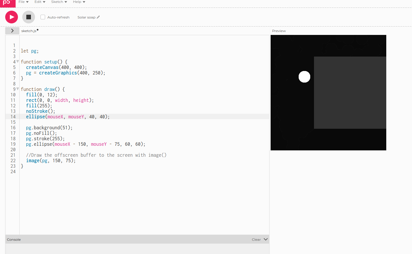
I went online to try P5js and had a look at the examples.
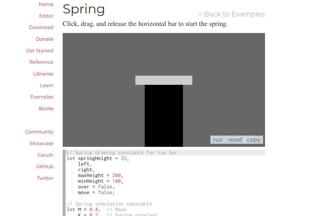
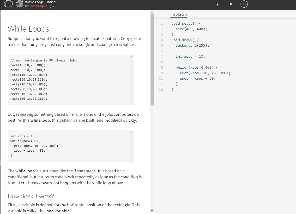
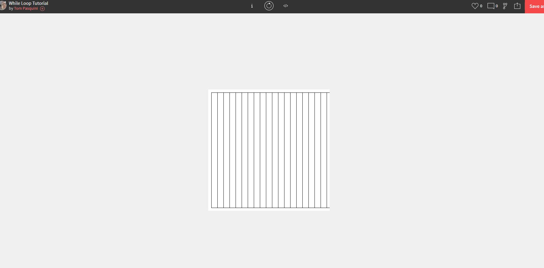
Openprocessing (online)
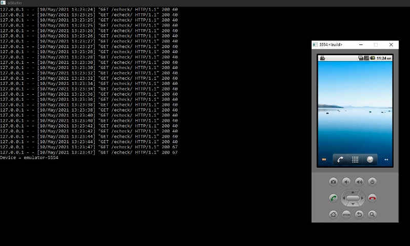
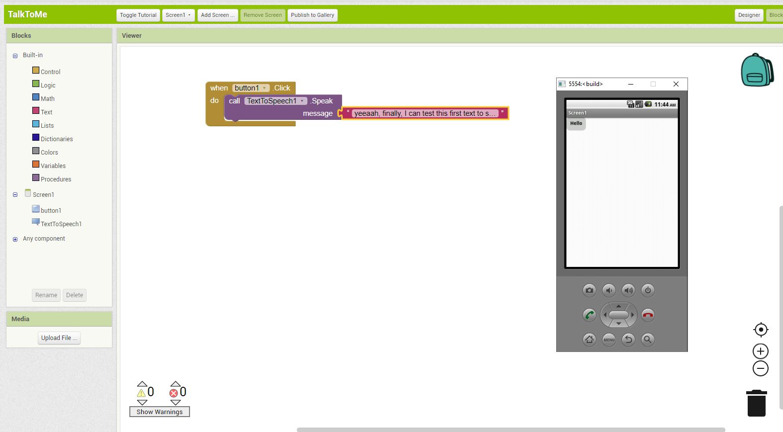
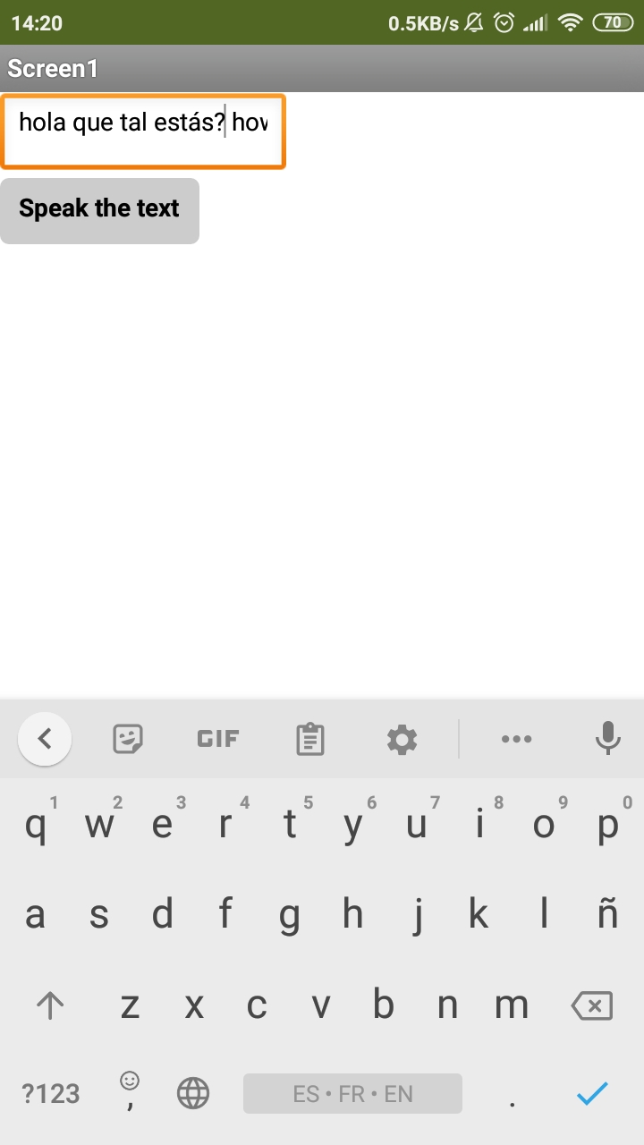
MITAppInventor, I followed a tutorial to create a text to speach application. After installing the emulator (aistarter), I had to update the android emulator and after quiet a while, I finally was able to try the text to speach app with the emulator...
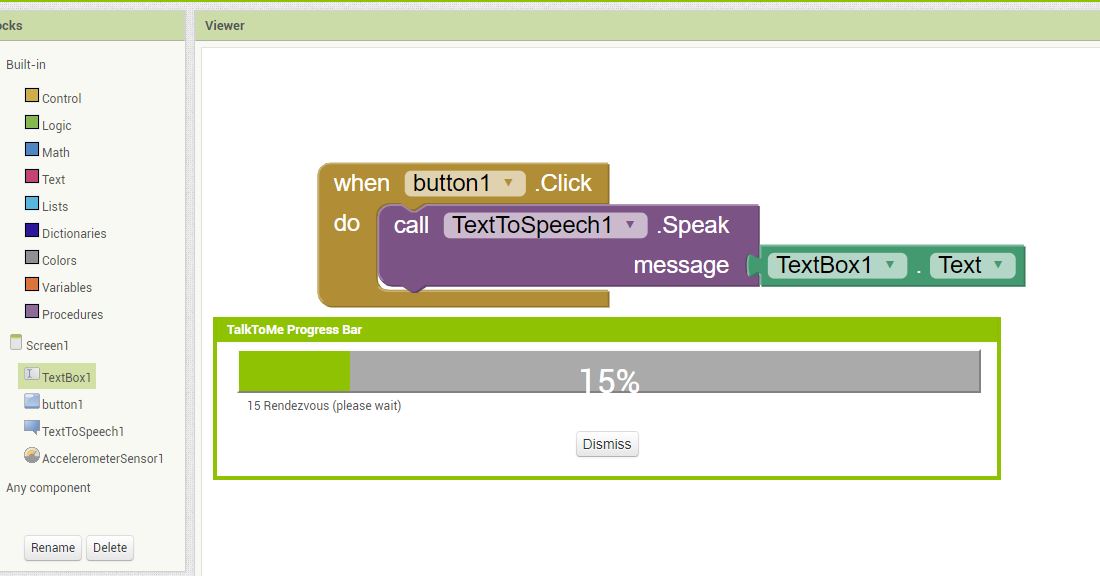
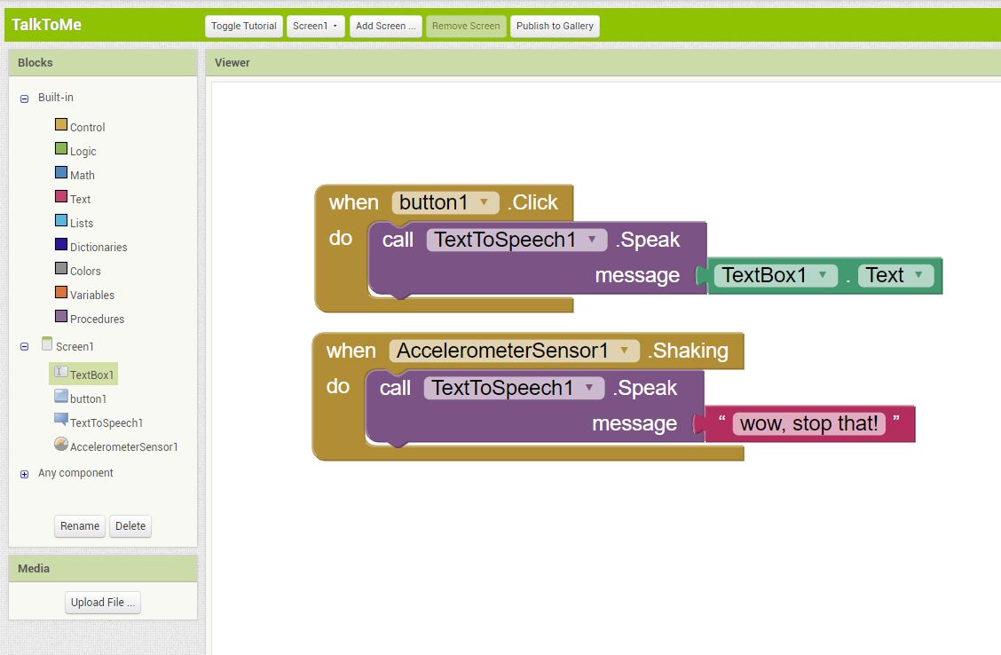
I then followed the "talk to me part2" tuto in which we can add a sensors (accelerometer in this case) and make the phone speak when shaken, also implemented by adding a text input box for the user. to test it, I installed the MIT AI2 companion app in my phone.
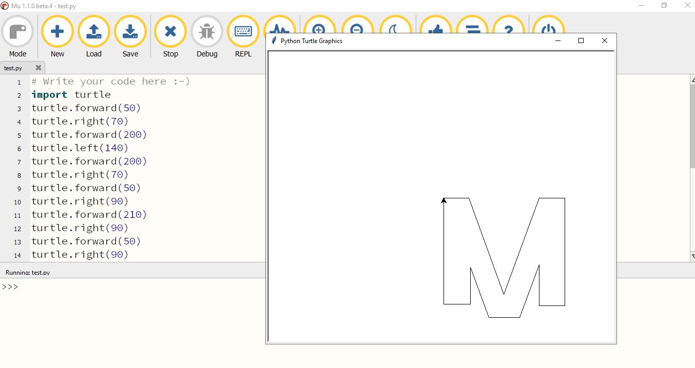
I have also tried the Micro python editor, MU Editor trying the turtle graphics...

Go to:Group assignment Individual assignment
Individual assignment
Write an application that interfaces a user with an input and/or output device that you made
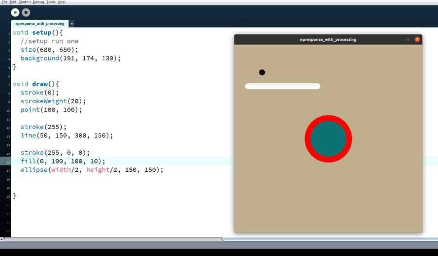
I started this week´s assignment by following Marta´s tutorial on Processing (cheat sheet), in order to get an introduction. I did a simple exercice, creating shapes.
I will now try to use my step response board from week10 to recieve and visualize the values that the electrodes transmites.
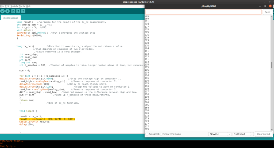
Following Adrin´s recomendation, I also mapped the values for this set of electrodes by looking at the highest and lowest results in the serial monitor (arduino IDE) and specifying the range I want to use, in my case, 0-680, it is the size of the canvas, I would like to see if I could maybe get my shape to fill it.
Here with this code, I am taking the sensor´s values from the serial port and displaying theses values in the shape of a circle, the size of the circle change depending on the value, not the best result, the circles are beeing painted one over the other...
								//Step response visualizer
								//Fabacademy 2021
								//Mickael P.

								import processing.serial.*;

								float stepResponseValue;  // sensor value variable
								Serial myPort;  // Serial port name
								float ellipseSize;  // Ellipse size variable

								void setup(){
								  //setup run one
								  size(680, 680);
								  println(Serial.list());
								  myPort = new Serial(this, Serial.list()[32], 9600);
								  myPort.bufferUntil('\n');
								  background(0, 25, 68);
								}

								void draw(){
								  ellipseSize = map(stepResponseValue, 0, 680, 0, 680);
								  stroke(65, 50, 120);
								  fill(0, 200, 200, 10);
								  ellipse(height/2, height/2, ellipseSize, ellipseSize);
								}

								void serialEvent(Serial myPort) {
								  String inString = myPort.readStringUntil('\n');
								  if (inString != null) {
									inString = trim(inString);
									float[] values = float(split(inString, ","));
									if (values.length >=1) {
									  stepResponseValue = values[0];
									}
								  }
								}
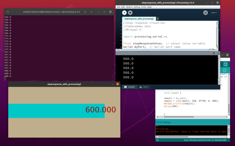
Here is an other, this time, I try to replicate Neil´s example. The values are displayed with both a changing shape and some text. I am using the same code as in week10 on the 412 board.
412 code
								//tx_rx03  Robert Hart Mar 2019.

								//ATtiny412

								//  Program to use transmit-receive across space between two conductors.
								//  One conductor attached to digital pin, another to analog pin.
								//
								//  This program has a function "tx_rx() which returns the value in a long integer.
								//
								//  Optionally, two resistors (1 MOhm or greater) can be placed between 5V and GND, with
								//  the signal connected between them so that the steady-state voltage is 2.5 Volts.
								//
								//  Signal varies with electric field coupling between conductors, and can
								//  be used to measure many things related to position, overlap, and intervening material
								//  between the two conductors.
								//


								long result;   //variable for the result of the tx_rx measurement.
								int analog_pin = 2;  //PA1
								int tx_pin = 3;  //PA2
								void setup() {
								pinMode(tx_pin,OUTPUT);  //Pin 3 provides the voltage step
								Serial.begin(9600);
								}


								long tx_rx(){         //Function to execute rx_tx algorithm and return a value
														//that depends on coupling of two electrodes.
														 //Value returned is a long integer.
									int read_high;
									int read_low;
									int diff;
									long int sum;
									int N_samples = 100;  //Num samples, Larger number slows it down,
									but reduces scatter.

									sum = 0;

									for (int i = 0; i < N_samples; i++){
									digitalWrite(tx_pin,HIGH);          //Step the voltage high on conductor 1.
									read_high = analogRead(analog_pin);   //Measure response of conductor 2.
									delayMicroseconds(100);            //Delay to reach steady state.
									digitalWrite(tx_pin,LOW);               //Step the voltage to zero on conductor 1.
									read_low = analogRead(analog_pin);    //Measure response of conductor 2.
									diff = read_high - read_low;   //desired answer is the difference between high and low.
									sum += diff;             //Sums up N_samples of these measurements.
									}
									return sum;
									}                   //End of tx_rx function.


									void loop() {

									result = tx_rx();
									result = map(result, 328, 97740, 0, 680);
									Serial.println(result);
									delay(100);


									}
Processing code
									//Step response visualizer
									//Fabacademy 2021
									//Mickael P.

									import processing.serial.*;

									float stepResponseValue;  // sensor value variable
									Serial myPort;  // Serial port name
									float rectWidth;  // Ellipse size variable

									void setup(){
									  //setup run one
									  size(750, 340);
									  println(Serial.list());
									  myPort = new Serial(this, Serial.list()[32], 9600);
									  myPort.bufferUntil('\n');
									  background(191, 174, 139);
									}

									void draw(){
									  rectWidth = map(stepResponseValue, 110, 680, 0, 750);
									  noStroke();
									  fill(0, 200, 200);
									  rect(0, height/3, rectWidth, height/3.6);

									  noStroke();
									  fill(191, 174, 139);
									  rect(rectWidth, height/3, width-rectWidth, height/3.6);

									  println(stepResponseValue);
									  fill(random(255),0,0);
									  text(stepResponseValue, stepResponseValue-100, height/2);
									  textSize(stepResponseValue/12);
									}

									void serialEvent(Serial myPort) {
									  String inString = myPort.readStringUntil('\n');
									  if (inString != null) {
										inString = trim(inString);
										float[] values = float(split(inString, ","));
										if (values.length >=1) {
										  stepResponseValue = values[0];
										}
									  }
									}
Here a video clip to see how it works...
Did not notice that I left the terminal open when starting processing and it looks like its following along...
Go to:Group assignment Individual assignment
Learning outcomes
Interpret and implement design and programming protocols to create a Graphic User Interface (GUI).
Have you?
Linked to the group assignment pageDocumented your processExplained the UI that you made and how you did itOutlined problems and how you fixed themIncluded original code (or a screenshot of the app code if that's not possibleIncluded a ‘hero shot/video’ of your application running with your board
Related weeks
Week 9 - Mechanical design / Machine design —
Processing was first explored as a control platform for the automated marble maze built in Week 9.
Week 13 - Networking and communications —
The Processing interface communicates with the ATtiny UART network via serial connection documented in Week 13.
Week 8 - Embedded programming —
Serial communication protocol established in Week 8 used as the foundation for the Processing interface.
Week 12 - Output device —
Processing interface used to trigger and control the vibration motors and LEDs in the output device board.
Final Project —
Processing interface integrated into the complete brain model system to control the audio and motor network.