Flip-Table
Overview
Flip Table is an Digital schedule Display which can be used in a class rooms for showing Time and scheduled subjects. This project is Completely made in FAB LAB Kerala, Kochi Regarding the Fabacadamy Diploma Course.
What will it do?
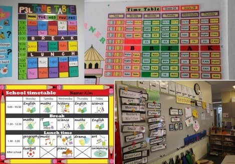
From the problem statement which I'm trying to do through this project is to solve the issues with the current school/college Time table showcasing system. The time table which mostly hanged on the class room's wall and near the black board where everybody in the class can see.So the important of the Time table is to prepare the students and teacher for engaging studying activity with a distributed time for each subjects and teacher.
So I'm reinventing the timetable system with this little project of mine with IoT features which gives the possibility of editing the timetable schedule live. The flipping mechanism is an attraction of this project feels good and happy when we see the high speed flipping.That's why I named this project 'Flip Table'.
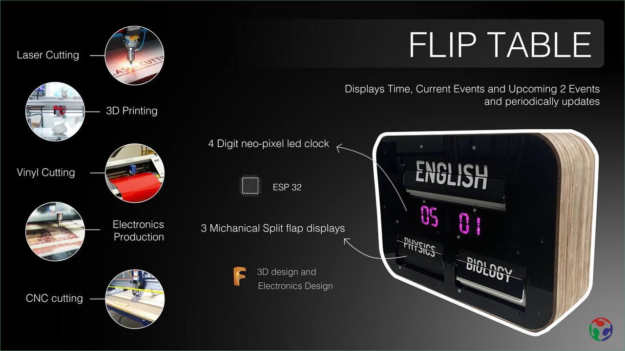
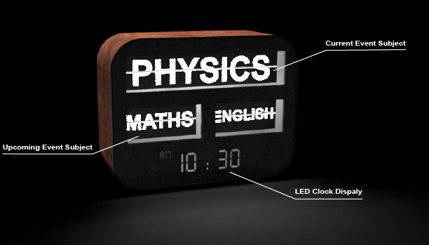
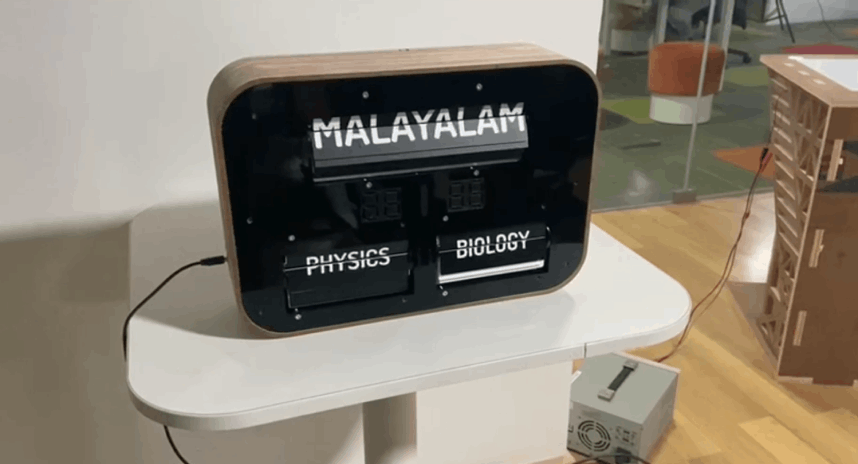
Basically this device has 3 mechanical split - flap display and a 4 digit full color 7 segment clock . It shows the current subject or event on the main split flap display segment which is already scheduled. Then the following two segments will shows the upcoming events or subject as per the schedule.The 4 digit 7 segment display shows the time. There will be an app which used to control the flip table and also can schedule or reschedule the events which is written on the split flap displays
Who's done what beforehand
This idea came to me while I was looking for an idea for a final project during my diploma course.No body done this yet,I searched over the internet. But the split flap displays are available and those are very common in airports,railway stations bus stations etc... But nowadays split flap displays are replacing with new LED Displays
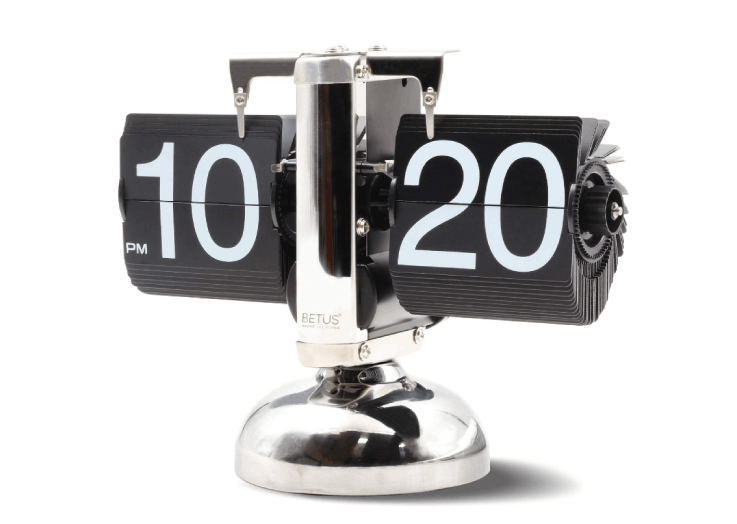
This was my first inspiration It's an mechanical split flap clock which has an open design shows the beauty of the mechanism while it rotates.It costs around ₹8K rupees( $100 USD) on amazon.
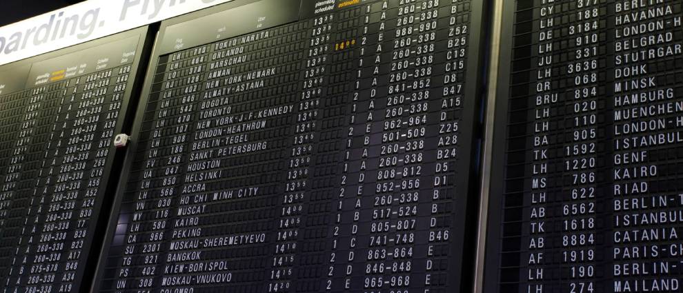
Here is a picture of a Split-Flap Scheduling Display from Frankfurt Airport,Germany. The sounds are very crazy to hear and fascinating.But nowadays these display's are replaced by the new Digital LED board Technologies.Watch the videos for feeling the sounds
- Split-Flap/Solari Departure Board, Frankfurt Airport 2006
- Split Flap Display by Oat Foundry | Old School Departures Boards
The split-flap displays at the airport also called Departure boards.For making those giant board required large mount of finding and time other skills as well.
Design Concept
It's a wall mounted design which basically will place on a classroom wall.It has 3 main flip mechanical display with LED back lights, and time clock under it.One of 3 display shows the current Subjects others are for upcoming subjects/events.
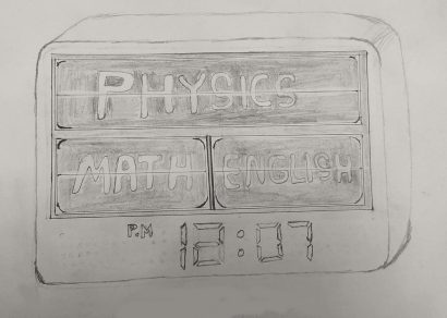
Here is the possible model 3D view which designed during the Design week
Researches and testing

From the vector file I've created during the Design week I calculated the approximate size and then laser cuts a dummy look out out of a cardboard.So through this I got an idea of how big my final project will be. then I found out that the 7 segment LED Clock will be the one which decides the size of the entire Project so I need to figure out the 7 segment first.
3D printed 7 segment Digits
My plan is to make the 7 segment modular digit using neopixel LEDs that gave me flexibility to use and no need to much wiring and easy to manage.
This is the neopixel LEDs that I'm going to use this comes with a pre-soldered PCB and i've almost 50 + of them I bought it from china years ago.Integrating neopixel LEDs are quit easy we just connect them all in a chain and just give the Data input to the Din pin of the first led in the chain.
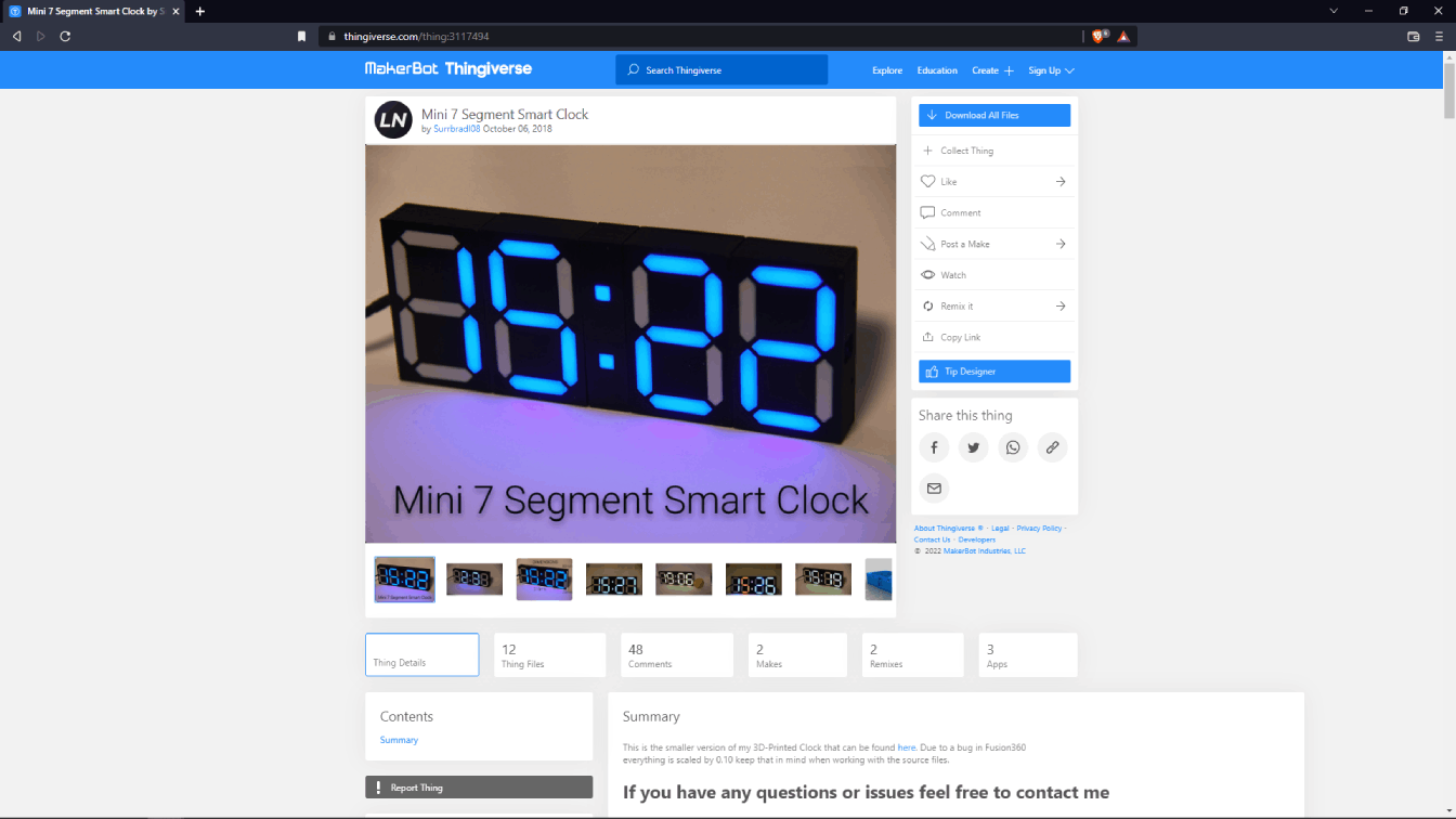
By digging on the internet for sometime I found this awesome 3D printed clock project using neo pixel and this is modular and exactly what i'm looking for. Click here for the project
I imported the stl file in the fusion which downloaded from the thingiverse. and started to make some changes for making it little bit larger and also wanted to fit for the neopixel LED I have
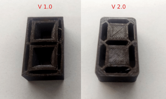
I also did some print testing to make sure about the design is oky or not, see the versions in above picture . The digit dimensions are 34 x 20 mm .
And the back side is optimized for the Neo pixel LED but I cant use the LED with the PCB which I have. So I have to get a Brand new SMD neopixel LEDS or I have to de solder each from the board and also needs to make a custom board for the digits.
After some iterations I finalized the design and made a 2 digit 7 segment display module then I 3D printed for Making the PCB with neopixel.
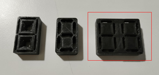
Here is my iteration results are and at the end I made the 2 digit 7 segment display module which is 3D printed.as next I need to make the 2 digit PCB for the Neo Pixel LEDs.
Split-Flap Mechanism
The Split-flap mechanism is one of the important part to this project because the whole thing works based on the mechanism and it is the main attraction too.
The 'Flap' making
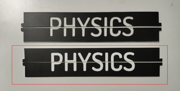
I tested the flaps after applying the vinyl one was transparent and other one is a white colored acrylic then the vinyl cut design which is in black applies on to of it.The transparent one is a bad choice it's better to go with the White acrylic flaps.
Then I designed one Split-flap module in fusion 360 which is inspired from the research I've done earlier turns out the size is too wide from my expectation so I tried to iterate the design again and reduced the size.
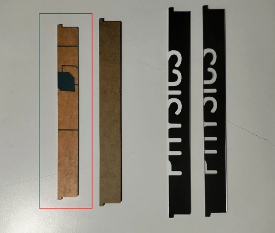
Here is the flap design I ended-up finally which fit for the size I was expecting
Then I completed the design in fusion 360 and exported the files for fabricating and running a very first test.
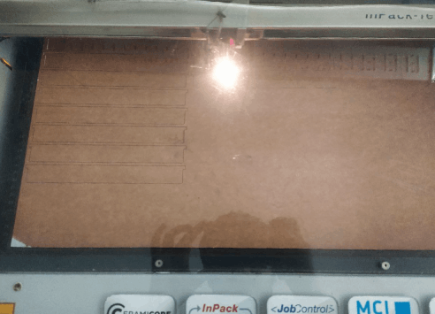
Arranged 18 pcs of flap design in a 1x2 sq feet area and then I cut them in a 2 mm acrylic white color sheet by the laser cutting process.
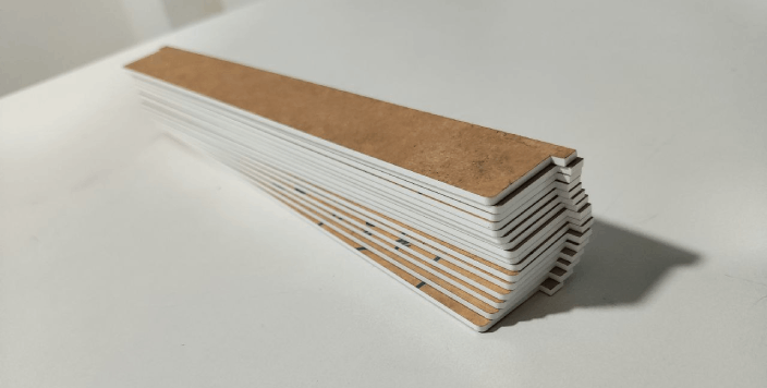
All flaps are same design I was actually worried about the weight of each flaps so then I Assembled them to run the test.
Testing the split-flap mechanism
I also attached the motor to the mechanism and used our machine week CN project board that we made for testing purpose.
Here is the fully calibrated single split-flapping test results in the above video. I was so exited to see the working of the mechanism.
Then I did some more coding to run it fast and change the flaps after each change to test the repeatability and the speed of the motor.The sound was awesome and very satisfying one to hear.
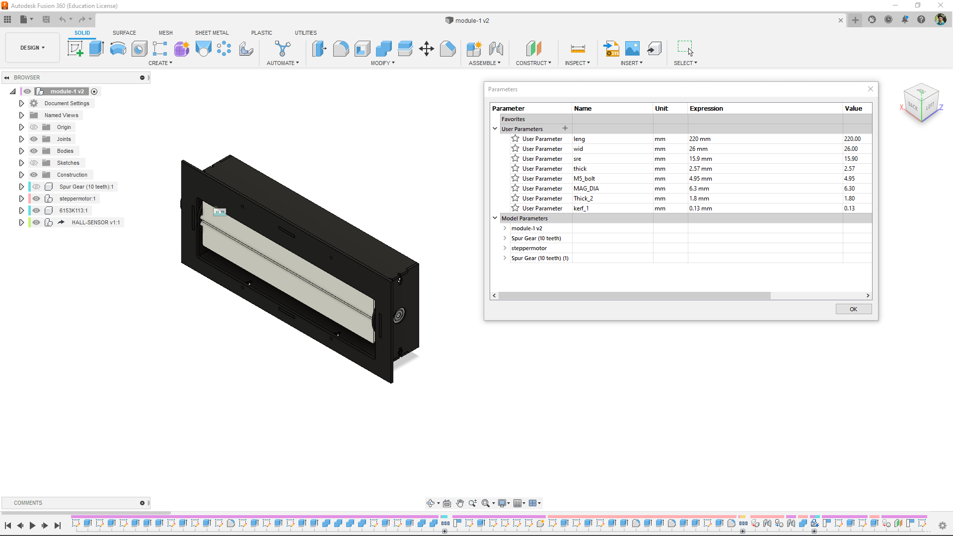
From the beginning of the design I was used the parametric feature to make one design for all the modules I need to make.
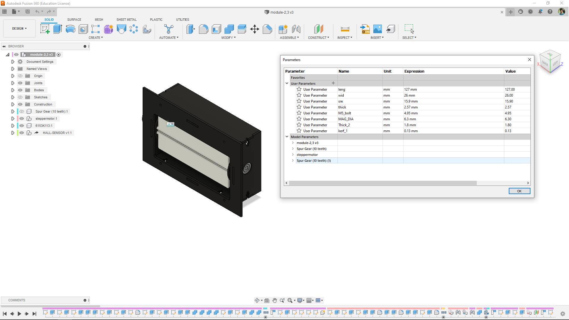
Here is the design for the module 2 and module 3 .Flip-Table totally need 3 split-flap- display and 2 of them are smaller than the main one so the parametric design helps me to create the smaller mechanism design without any extra efforts
Inside Electronics
in Electronics I already have a great plan because it is my strong area and well aware of the components and process and everything
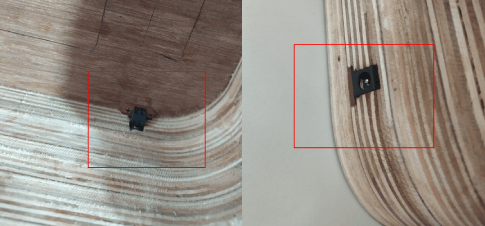
The Hall-Effect sensor
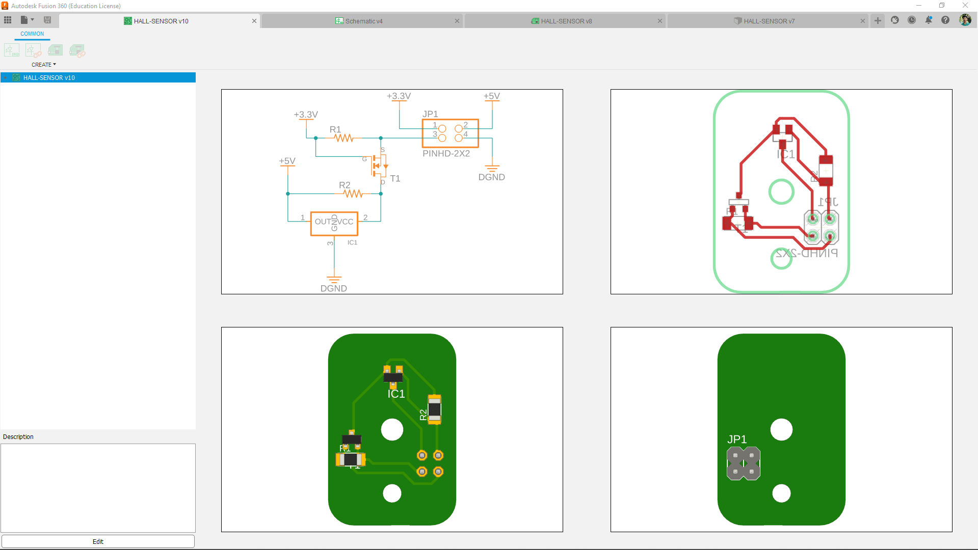
I've designed the hall-effect sensor with a logic level shifter circuit becouse the sensor works in 5v and the ESP32 works in 3.3 v.
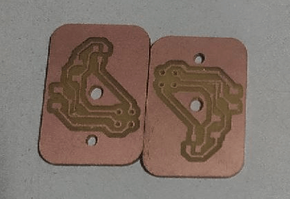
Then I milled out the boards 3 of them and soldered the components in place.
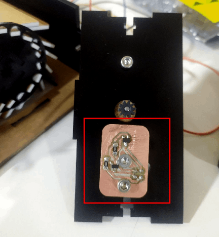
Then I modified the split-flap mechanism I made earlier and reconstructed the motor mount side of the acrylic part with the the Hall effect sensor.
4 digit Clock display
The 4 digit display PCB deigning is little bit challenge for me because the all 14 LEDs must in place according to the 3D printed part I've designed
One design is enough for both 4 digit display just need to make double PCB and the connectivity will be little tricky need to make special cable to connect all together.
Then I also made a two LED PCB for the dots place in between the 2 2 digit display.
And then I milled the PCB and solders the Neo pixel LED's in place.
The ESP32 Controller
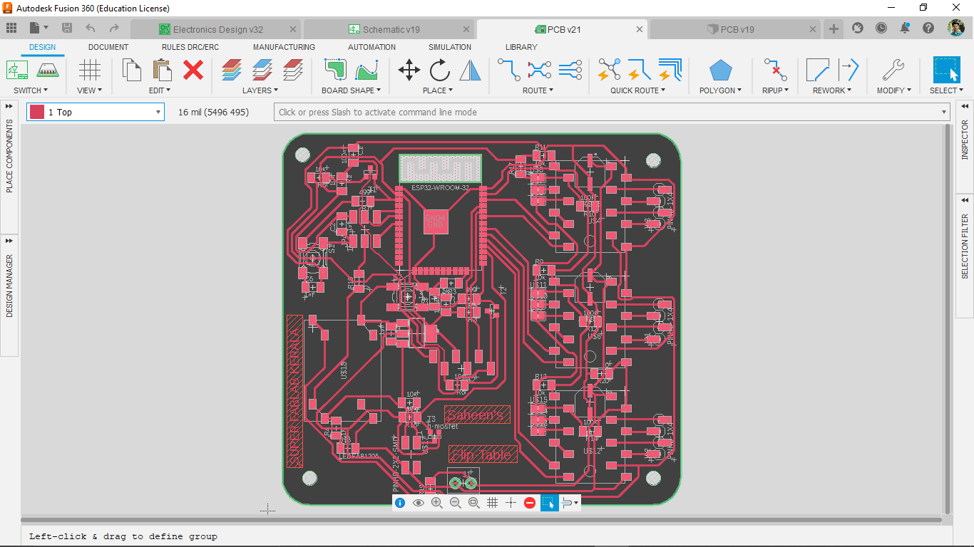
It took 2 days for me to design and make the main Control board of the Flip-Table project . There is a lot of things to account and lots needs to figured out.
The whole trace is done on the TOP of the PCB and It was very hard to trace everything on the top with some zero ohm resister helps I got it cleared.
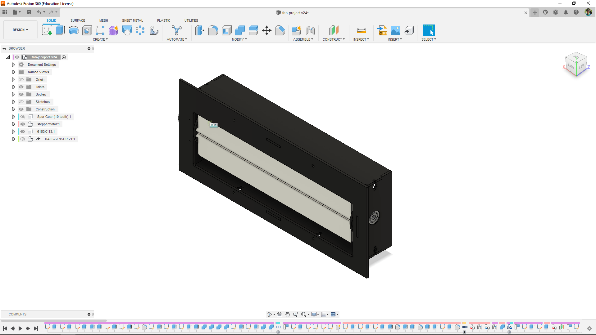
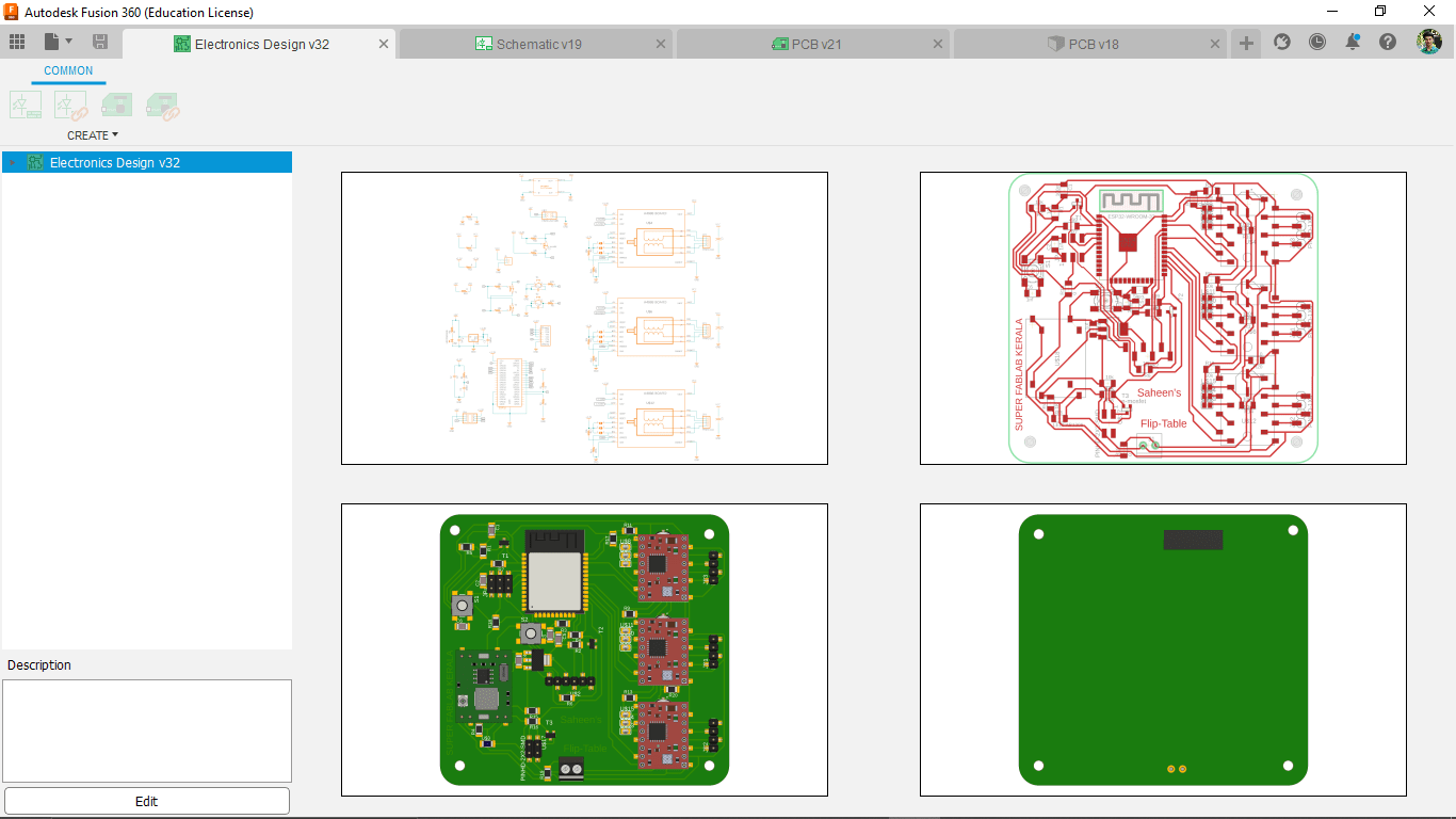
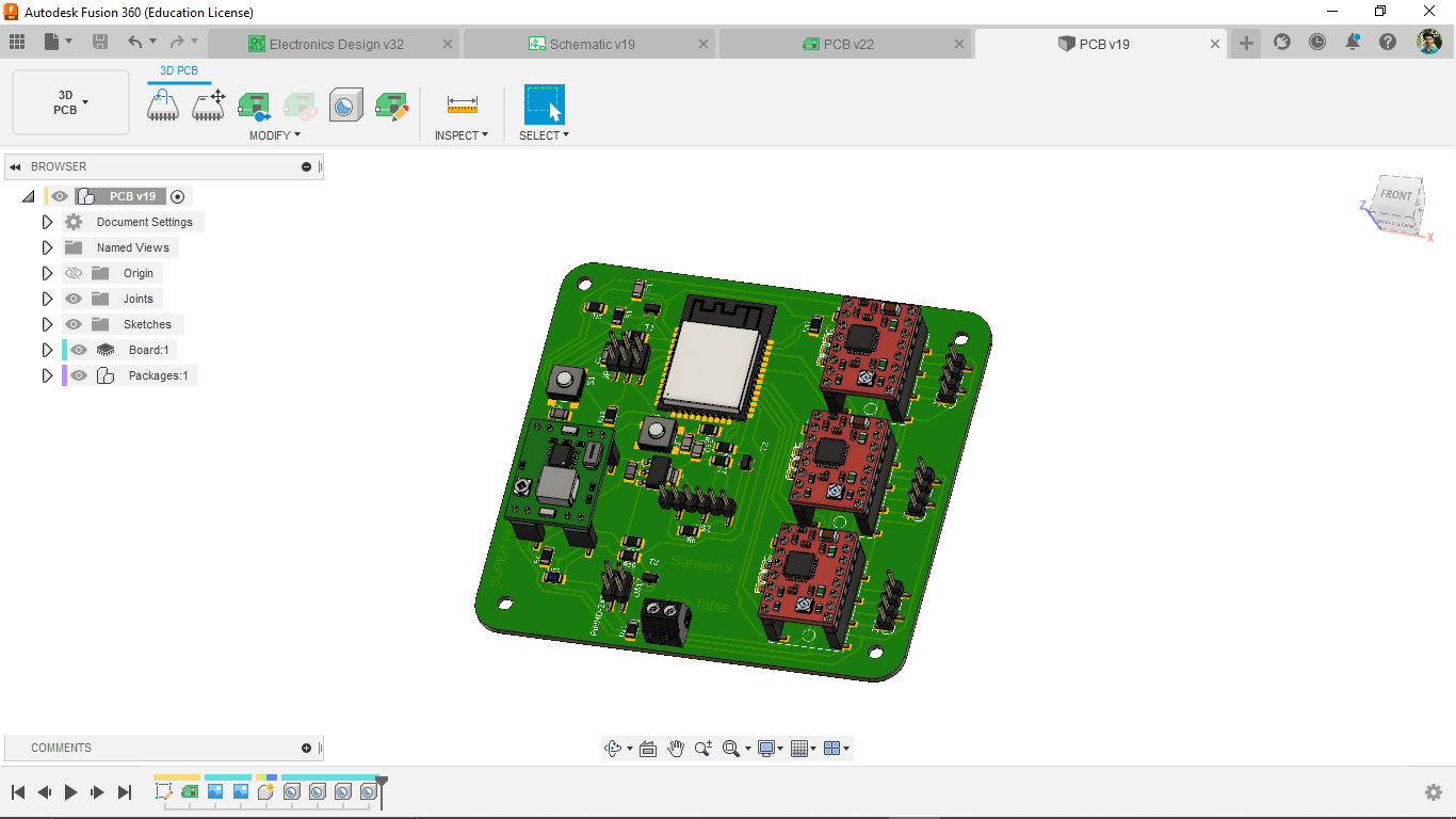
Then I also made 3D model from the PCB design for documentation purpose . This is actually a time killing process if we don't have all the 3D model library fot the Electronics components.
Then I milled out the PCB and soldered all the components in place
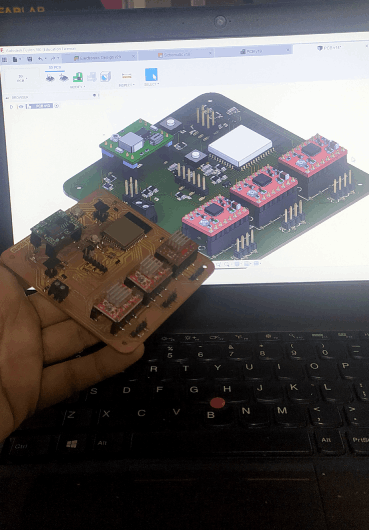
See the above figure how close I got the end result from the 3D model Design.
Power Jack
I did not added any DC power jack to the Controller board because The adapter that I've is a 12v 2A rated one. So, I've to convert the voltage to 7v for the motor driver.The power jack will be a separate board and the power supply is a an external adapter.
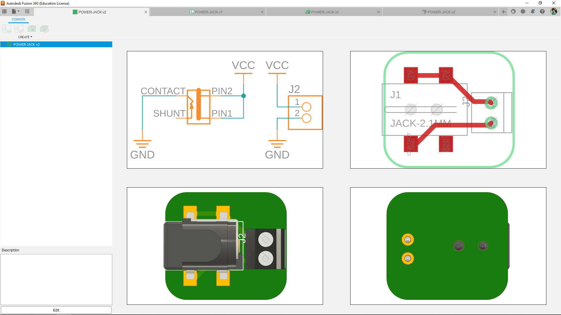
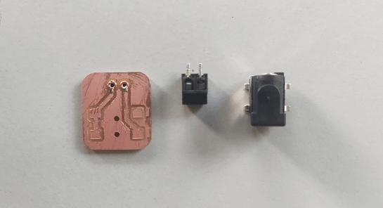
This board only contain the power jack and a 2 pin terminal block connector and the board will attach to the final enclosure.
4 digit 7 Segment clock display
From the starting of the project I already designed the 2 digit 7 segment display 3D printed version then I also made the Neo pixel PCBs
I did some design changes to make a press fit at the front panel also designed the cover for the dots.
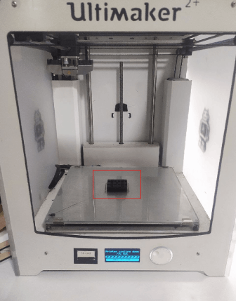
Then I printed them all in the Ultimaker . this will be only part that 3D printed in this project
Here is the final number test I ran using an arduino UNO board and some code. It lights up awesome.
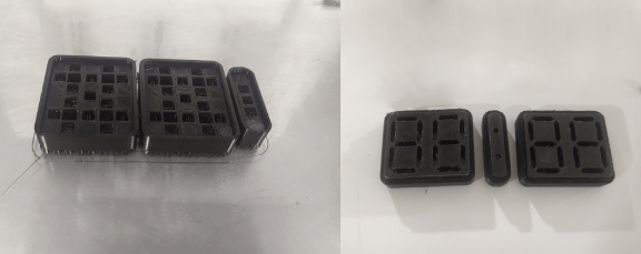
Final Enclosure Design and Making
The final enclosure design is already intended to do in wood so I redesigned the shape layer by layer to stack 2D profile CNC cut Plywood sheet and put together to get final target.
The layers in the design is based on 18 mm thick plywood sheet and a small 12mm for the final back plane of the enclosure.The first layer has an pocket cut for the front panel integration
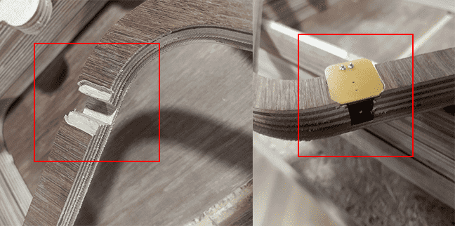
The pocket for the DC Power jack I made earlier was perfect fit in the plywood layer.
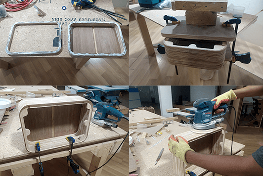
Then I glued all the layers together and sanded the enclosure as well for getting the wooden finish.
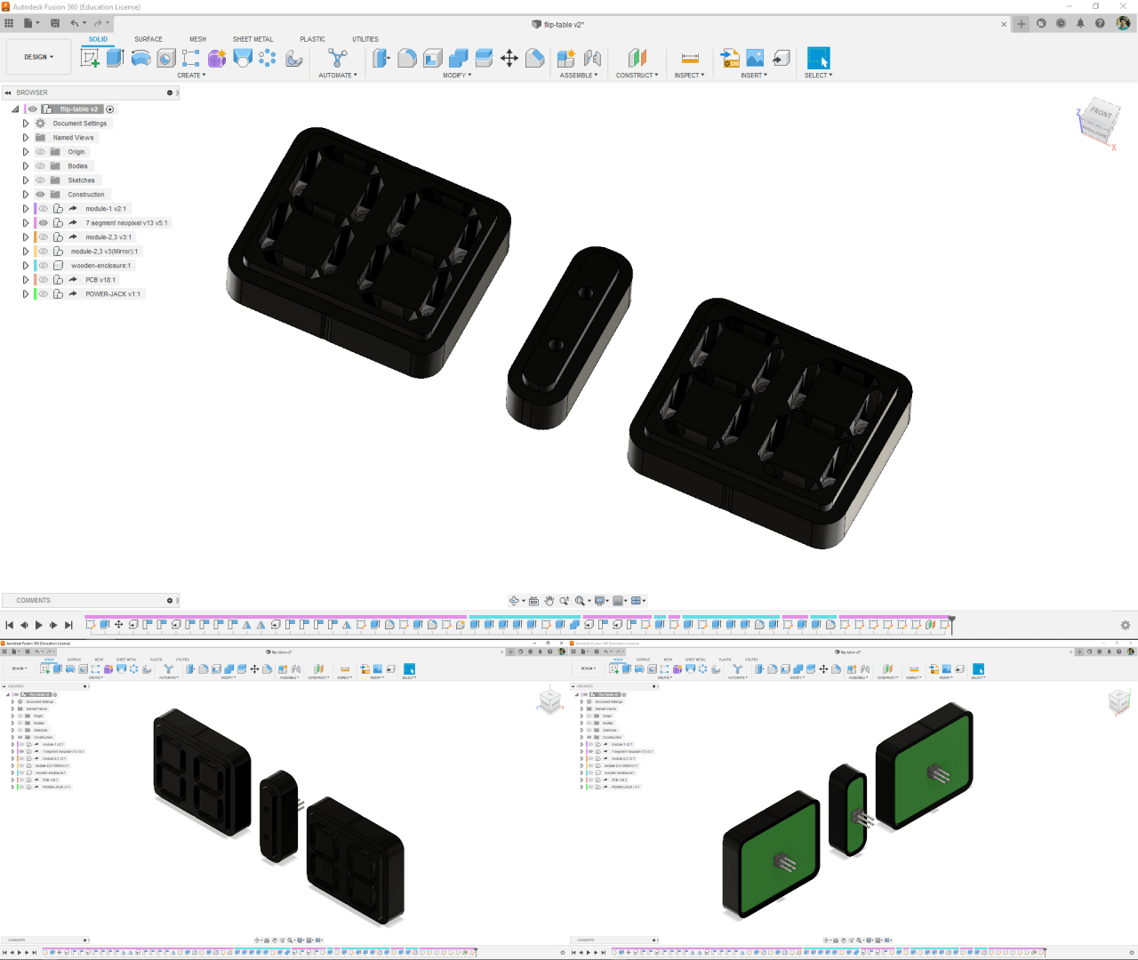
Final designing and Assembling
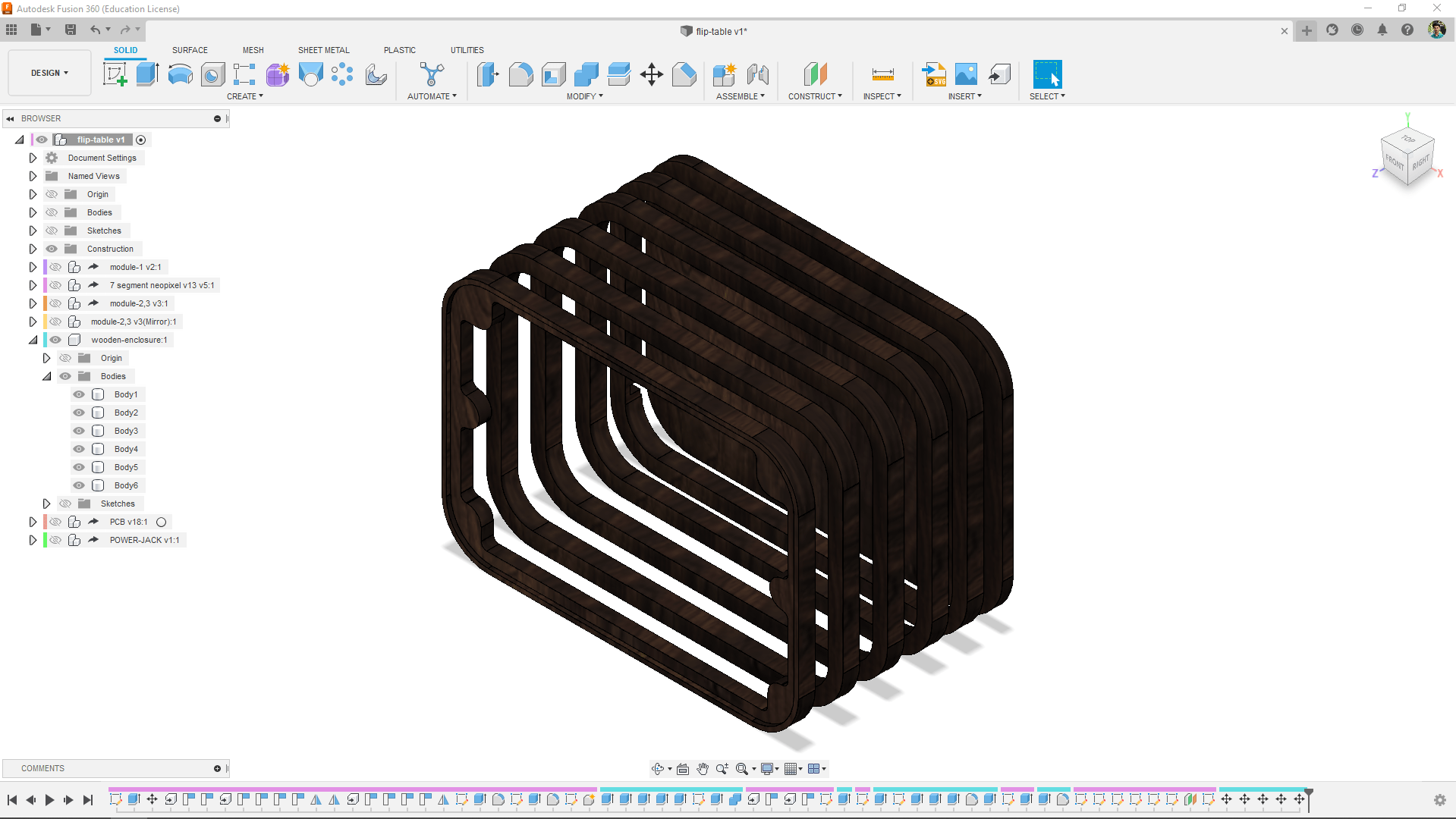
I clubbed all the parts to gether in design and rendered the output as well. So that made my job pretty much easier that I can follow the design in order to assemble the Flip-Table.
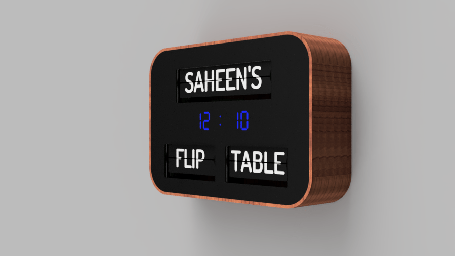
The above figure show the fusion 360 rendered output that the Flip-Table placed on a wall
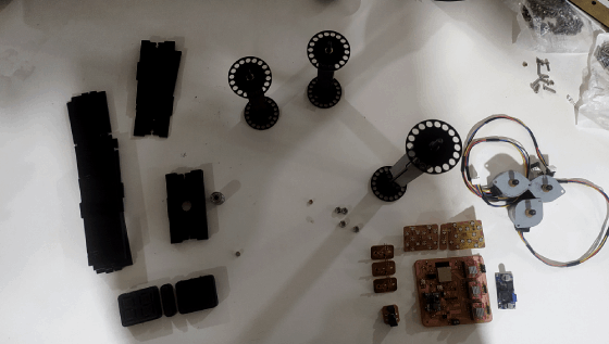
I arranged all parts on the table after all the machining process and started to assemble them together by following the design.
Firstly assembled the front panel without the flaps. the Flaps can be add after everything is done
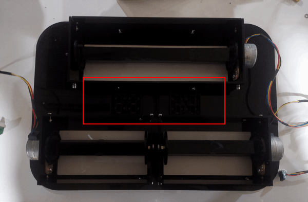
Then I place the 4 digit clock and the dots in place
The power jack PCB was so perfect to see after assembling to the enclosure.
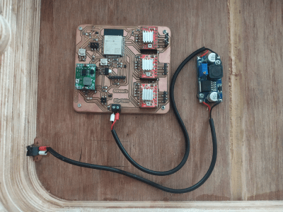
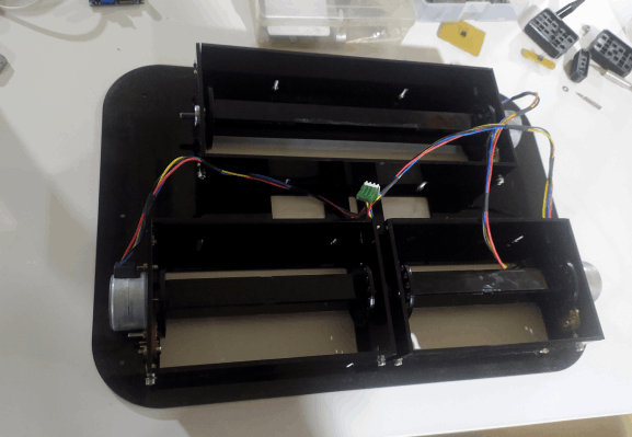
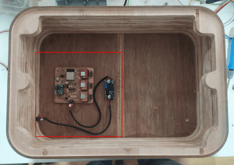
And then I screwed the ESP32 based Flip-Table controller board and wired to the power jack with the buck converter module in between.
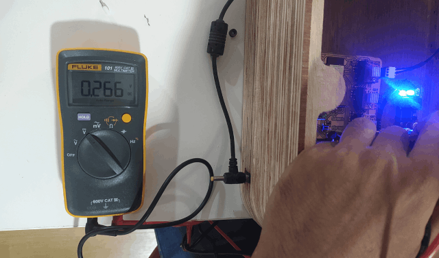
Then I set the voltage to 7v volt by turning the pot on the module and with the help of the Digital Multimeter.
The back enclosure is done now I just need to plug all the cables from the front panel and fix the front panel on the wooden enclosure.
Programing the Flip Table
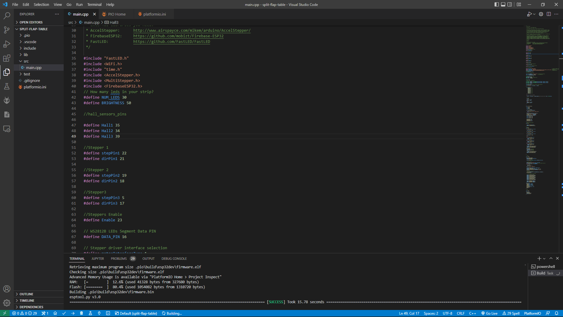
I wrote the program in platformIO because the PlatformIO is very friendly and time saving IDE while programing especially for ESP32
Saheen's Flip Table main.cpp CODE :-
/*
* MIT License
*
* Copyright (c) 2018 SHAEEN PALAYI
*
* Fab Academy 2021 student from Super FAB LAB Kerala,India
*
* Permission is hereby granted, free of charge, to any person obtaining a copy
* of this software and associated documentation files (the "Software"), to deal
* in the Software without restriction, including without limitation the rights
* to use, copy, modify, merge, publish, distribute, sublicense, and/or sell
* copies of the Software, and to permit persons to whom the Software is
* furnished to do so, subject to the following conditions:
*
* The above copyright notice and this permission notice shall be included in all
* copies or substantial portions of the Software.
*
* THE SOFTWARE IS PROVIDED "AS IS", WITHOUT WARRANTY OF ANY KIND, EXPRESS OR
* IMPLIED, INCLUDING BUT NOT LIMITED TO THE WARRANTIES OF MERCHANTABILITY,
* FITNESS FOR A PARTICULAR PURPOSE AND NONINFRINGEMENT. IN NO EVENT SHALL THE
* AUTHORS OR COPYRIGHT HOLDERS BE LIABLE FOR ANY CLAIM, DAMAGES OR OTHER
* LIABILITY, WHETHER IN AN ACTION OF CONTRACT, TORT OR OTHERWISE, ARISING FROM,
* OUT OF OR IN CONNECTION WITH THE SOFTWARE OR THE USE OR OTHER DEALINGS IN THE
* SOFTWARE.
*
* Source:
* https://
*
* External libraries you need:
* AccelStepper: http://www.airspayce.com/mikem/arduino/AccelStepper/
* FirebaseESP32: https://github.com/mobizt/Firebase-ESP32
* FastLED: https://github.com/FastLED/FastLED
*/
#include "FastLED.h"
#include < WiFi.h>
#include "time.h"
#include < AccelStepper.h>
#include < MultiStepper.h>
#include < FirebaseESP32.h>
// How many leds in your strip?
#define NUM_LEDS 30
#define BRIGHTNESS 50
//hall_sensors_pins
#define Hall1 35
#define Hall2 34
#define Hall3 39
//Stepper 1
#define stepPin1 22
#define dirPin1 21
//Stepper 2
#define stepPin2 19
#define dirPin2 18
//Stepper3
#define stepPin3 5
#define dirPin3 17
//Steppers Enable
#define Enable 23
// WS2812B LEDs Segment Data PIN
#define DATA_PIN 16
// Stepper driver interface selection
#define motorInterfaceType 1
//Wifi Configuration
#define WIFI_SSID "saheen_palayi" // input your home or public wifi name
#define WIFI_PASSWORD "1234567890" //password of wifi ssid
#define FIREBASE_HOST "https://flip-table-dc978-default-rtdb.firebaseio.com/Flip_Table" //firebase url
#define FIREBASE_AUTH "AIzaSyBKfIOTASFZG3oOOqO7HXUQNuxaUCDq1cY" //firebase api key
FirebaseData firebaseData;
String mystring;
//ntp Library configuration
const char *ntpServer = "pool.ntp.org"; // World Wide ntp Server
const long gmtOffset_sec = 19800; // for GTM +5:30
const int daylightOffset_sec = 0;
// Define the array of leds
CRGB LEDs[NUM_LEDS];
CRGB color = 0xFF007F; //hexcode color
CRGB color1 = 0x000000;
boolean flag;
//stepper motor configuration
AccelStepper stepper1 = AccelStepper(motorInterfaceType, stepPin1, dirPin1);
AccelStepper stepper2 = AccelStepper(motorInterfaceType, stepPin2, dirPin2);
AccelStepper stepper3 = AccelStepper(motorInterfaceType, stepPin3, dirPin3);
MultiStepper steppers;
long positions[3]; // Array of desired stepper positions
void displayTime(int startindex, int number)
{
byte numbers[] = {
0b00111111, // 0
0b00000110, // 1
0b01011011, // 2
0b01001111, // 3
0b01100110, // 4
0b01101101, // 5
0b01111101, // 6
0b00000111, // 7
0b01111111, // 8
0b01101111, // 9
};
for (int i = 0; i < 7; i++)
{
LEDs[i + startindex] = ((numbers[number] & 1 << i) == 1 << i) ? color : CRGB::Black;
}
// Dots
if(flag)
{
LEDs[14] = color;
LEDs[15] = color;
}
else{
LEDs[14] = color1;
LEDs[15] = color1;
}
}
void printLocalTime()
{
char h[80];
char m[80];
char p[80];
struct tm timeinfo;
if (!getLocalTime(&timeinfo))
{
Serial.println("Failed to obtain time");
return;
}
Serial.println(&timeinfo, "%H:%M:%S");
strftime(h, 80, "%I", &timeinfo);
strftime(m, 80, "%M", &timeinfo);
strftime(p, 80, "%p", &timeinfo);
Serial.println((m[1] - 48));
int hl = (h[0] - 48);
int hr = (h[1] - 48);
int ml = (m[0] - 48);
int mr = (m[1] - 48);
displayTime(0, hr);
displayTime(7, hl);
displayTime(16, mr);
displayTime(23, ml);
}
//Stepper Moving function
void Mov()
{
steppers.moveTo(positions);
steppers.runSpeedToPosition();
}
//Homing
void Home()
{
if (digitalRead(Hall1) == LOW)
{
positions[0] = 2000;
}
if (digitalRead(Hall2) == LOW)
{
positions[1] = 2000;
}
if (digitalRead(Hall3) == LOW)
{
positions[2] = 2000;
}
Mov();
while (digitalRead(Hall2))
{
stepper1.setSpeed(2000);
stepper1.run();
}
while (digitalRead(Hall3))
{
stepper2.setSpeed(2000);
stepper2.run();
}
while (digitalRead(Hall1))
{
stepper3.setSpeed(2000);
stepper3.run();
}
stepper1.setCurrentPosition(0);
stepper2.setCurrentPosition(0);
stepper3.setCurrentPosition(0);
delay(1000);
positions[0] = 5;//right
positions[1] = 9;//main
positions[2] = 8;//left
Mov();
stepper1.setCurrentPosition(0);
stepper2.setCurrentPosition(0);
stepper3.setCurrentPosition(0);
}
// setup
void setup()
{
Serial.begin(115200);
FastLED.setBrightness(BRIGHTNESS);
FastLED.delay(3000);
FastLED.addLeds(LEDs, NUM_LEDS);
//connect to WiFi
Serial.printf("Connecting to %s ", WIFI_SSID);
WiFi.begin(WIFI_SSID, WIFI_PASSWORD); //try to connect with wifi
while (WiFi.status() != WL_CONNECTED)
{
delay(500);
Serial.print(".");
}
Serial.println(" CONNECTED");
Firebase.begin(FIREBASE_HOST, FIREBASE_AUTH);
Firebase.reconnectWiFi(true);
Firebase.setReadTimeout(firebaseData, 1000 * 60);
Firebase.setwriteSizeLimit(firebaseData, "tiny");
delay(100);
//init and get the time
configTime(gmtOffset_sec, daylightOffset_sec, ntpServer);
printLocalTime();
//setting speed and acceleration
stepper1.setMaxSpeed(2000);
stepper1.setAcceleration(3000);
stepper1.setCurrentPosition(0);
stepper2.setMaxSpeed(2000);
stepper2.setAcceleration(3000);
stepper2.setCurrentPosition(0);
stepper3.setMaxSpeed(2000);
stepper3.setAcceleration(3000);
stepper3.setCurrentPosition(0);
steppers.addStepper(stepper1);
steppers.addStepper(stepper2);
steppers.addStepper(stepper3);
flag = false;
pinMode(Hall1, INPUT);
pinMode(Hall2, INPUT);
pinMode(Hall3, INPUT);
pinMode(Enable, OUTPUT);
delay(100);
digitalWrite(Enable, LOW);
delay(100);
Home();
}
//loop
void loop()
{
flag=!flag;
delay(500);
printLocalTime();
FastLED.show();
}
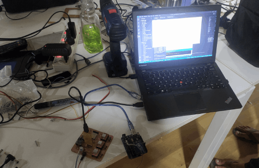
The programing was done before the assembly but some debugging was required even after the assembly and The Neo pixel did not works like I planned.
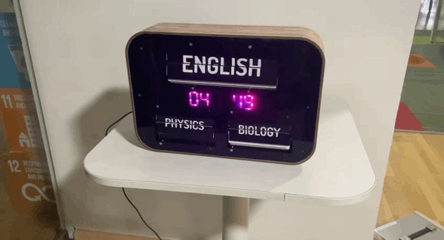
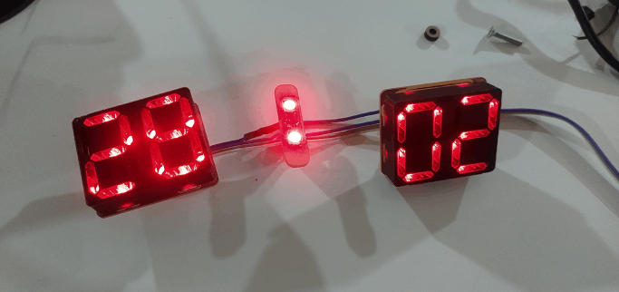
here is the working image which shows the time of 4:49 at the evening in magenta color but we can see one pixel is missing the neo pixel clock was disaster in the project.but It works anyway.
Final Presentation Video
References
Downloads
- Split-Flap Mechanism Design Files
- Flip-Table Program Files
- Flip-Table Final Design Files