FAB FTDI
Overview
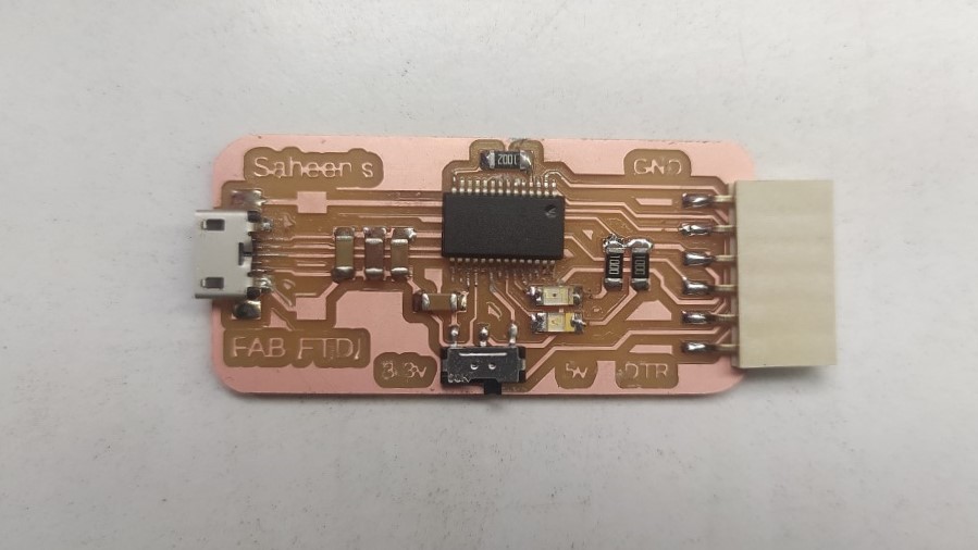
To program ESP WROOM 32 modules used in my final project and the ESP32 Walkie-talkie communication project I've to use a USB to Serial Communicator device. We have USB to FTDI converters in the lab to program the ESP32 modules but they are too expensive and only available Few . So I've decided to make my own FAB FTDI converter using the FT232rl Chip to program and read serial microcontrollers like esp32 and AVR 1 series chips.
References and Features
During FAB Embedded Programming week I've remember that Neil showed us a version DIY FAB FTDI that can be replicated for creating our own FAB FTDI
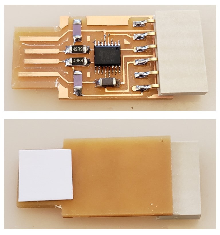
This simple Fab hello.USB-serial.FT230X version of FTDI USB to serial converter by Neil uses a FT230XS chip. Luckily, I found the chip in our lab inventory so I can replicate the FTDI same as Neil's design
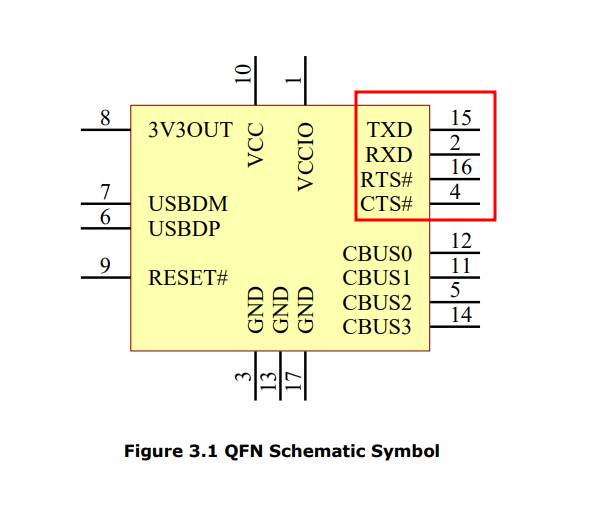
After referring the FT230XS chip's Data sheet I realize the chip doesn't provide a important pin out that I wanted. I'm referring a ESP32 Dev board schematic to understand the auto programming which is from espressif.
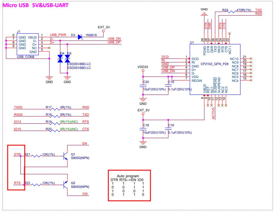
So according to the schematic and ESP32 SOM's datasheet I need the DTR and RTS pins from the Serial bridge chip to perform the auto program using the IDE. turns out the normal FTDI cable std doesn't comes with the DTR pin which is stands for "Data Ready". After a little bit googling I got know that there is a variant of FTDI chip which have the DTR pin to full fill my need.
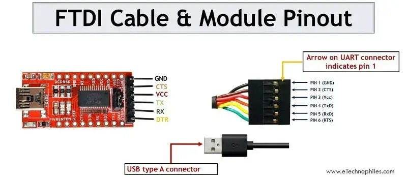
The FTDI chip which have the DTR pins also comes as a FTDI module which I can use directly for my programming developments. The FTDI chip name is FT232rl and for my goodness it's also available at our lab's inventory boosts my confident make a dedicated fab FTDI which can be fabricated in our own fab way of making PCBs.
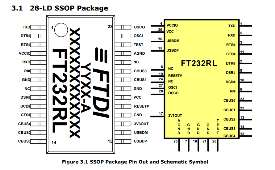
This chip have the full pins with the USB support and including 3v3,5v power support to make a perfect serial bridge for microcontroller programming. The only challenge that I need to take care is the design of the PCB for Fabricating in fablab because the chips pins are very thin makes the soldering difficult even the milling process
Design
I've designed the PCB for the FTDI serial bridge using fusion 360. with the slide switch which help full to switch the logic level between 5v and 3.3v.

Most of the schematic design is done by the instruction of the FT232rl's Data sheet which is documented very nicely and in detail, very helpful guid to design the circuit.

Then I routed the PCB in fusion and kept all the connections in the single layer only which makes the PCB fabrication very simple. and the Design rules also an important thing here so I had to adjust some parameters here for the too close trace foot prints. The USB socket foot print is a multi standard socket type which means it support both micro and min USB. the Foot print I made during my Electronics production week.

Then I converted the design to the the 1000 dpi Png layers of the traces, outline for milling the PCB and then I did mill the board and here is the result.
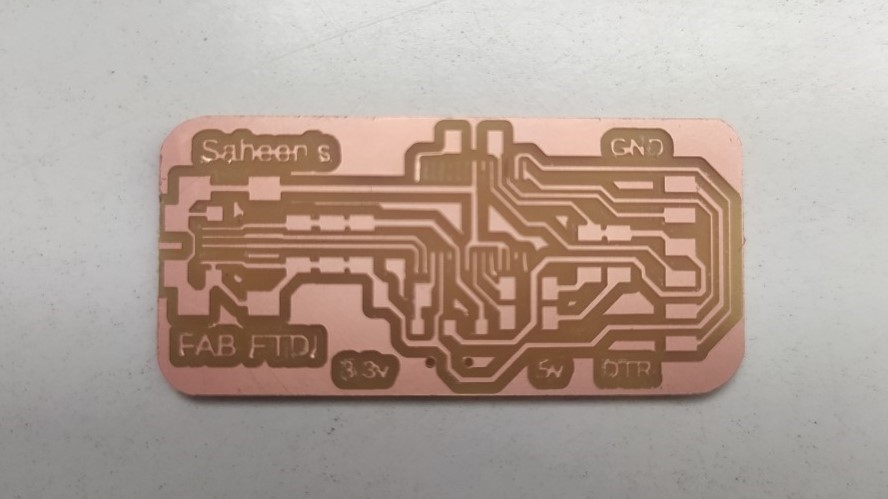
It came out like this not so great because of the slim lines didn't came completely but it didn't miss all the wanted traces for the working of the entire circuit. First try the board failed completely I found this happens because of the inaccuracy of the machine that we have in our lab. I used the new 1/64 End mill to mill the second board which was a success.
soldering
The BOM of the Circuit is very simple just few coupling capacitors and Leds, resisters alongside the FT232rl chip
BOM:
| Sl No: | Part Name | Value |
|---|---|---|
| 1 | U1 | FT232rl |
| 2 | S1 | SPDT Slide switch |
| 3 | USB port | Micro or Mini USB socket |
| 4 | D1 | Blue LED |
| 5 | D2 | Red LED |
| 6 | C1,C2 | 100nF |
| 7 | C3 | 10nF |
| 8 | C4 | 1uF |
| 9 | R1 | 10K |
| 10 | R2,R3 | 100 ohm or 499 ohm |
| 11 | FTDI | 6 POS SMD socket |
I used the USB micro to solder and soldering the chip and micro was little tricky because the pins are too close each other so I had to use the de-solder wick technique to clean them up after the soldering thanks to my precise soldering skill set

I didn't added any power led to verify the power but I had it verified using a multimeter to ensure the 5v supply is coming correctly.
Testing
Here is my test setup of the board that it is working as a serial bridge in between a computer and the microcontroller board we build at fablab. I'm using an input device board of Pallab Shrestha to just to test the serial data transfer.
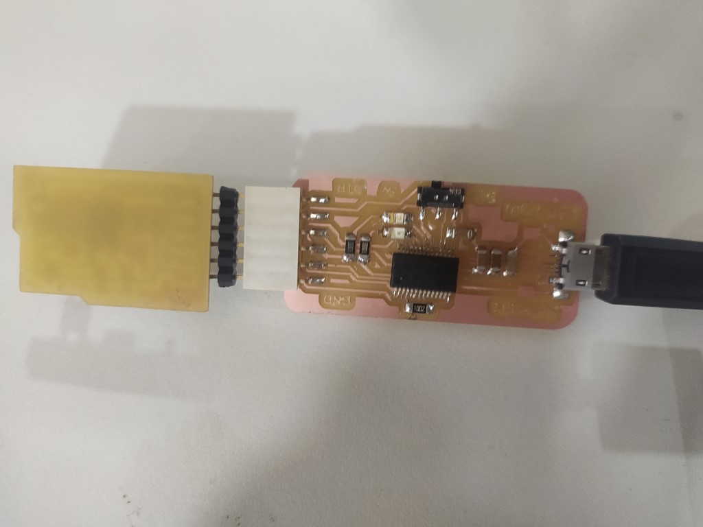
But for some reason the microcontroller board is upside down to visible due to its design orientation of the FTDI connector on board.
And the UART Serial data transfer is working perfectly and fast! the FAB-FTDI design is a success. look at the LEDs! which glowing while the data transfer happens!! very Cool!!
References
- Fab Academy Electronics Production classes
- Roland MDX 20
- AVR FREKS community website
- FabTinyISP
- Trotec Speedy Laser Engraving Machine
Downloads
- Saheen's FAB FTDI Files