Use this command to minimize a video using FFMPEG: ffmpeg -i input.mp4 -vcodec libx265 -crf 28 output.mp4
                  import cv2 as cv
import sys
import numpy as np
import threading

cap=cv.VideoCapture(0)
#NUMBER OF TIMES THE BRIGHTNESS HAS BEEN ABOVE 6900
LIGHT_COUNT = 0

#NO. OF TIMES THE BRIGHTNESS HAS BEEN BELOW 2000
BREAK_COUNT = 0

#to know if the transmission started
e = False
#timer
timer = 0

str = ''

def convertMorseToText(s):

    morseDict={
        '' : 'Check',
    '.-': 'a',
    '-...': 'b',
    '-.-.': 'c',
    '-..': 'd',
    '.': 'e',
    '..-.': 'f',
    '--.': 'g',
    '....': 'h',
    '..': 'i',
    '.---': 'j',
    '-.-': 'k',
    '.-..': 'l',
    '--': 'm',
    '-.': 'n',
    '---': 'o',
    '.--.': 'p',
    '--.-': 'q',
    '.-.': 'r',
    '...': 's',
    '-': 't',
    '..-': 'u',
    '...-': 'v',
    '.--': 'w',
    '-..-': 'x',
    '-.--': 'y',
    '--..': 'z',
    '.-.-': ' '
    }

    return (morseDict.get(s))

while True:
    # Capture frame-by-frame
    ret, frame = cap.read()
    # if frame is read correctly ret is True
    if not ret:
        print("Can't receive frame (stream end?). Exiting ...")
        break
    # Our operations on the frame come here
    gray = cv.cvtColor(frame, cv.COLOR_BGR2GRAY)
    mask = np.zeros(gray.shape[:2], dtype="uint8")
    cv.circle(mask, (320, 240), 50, 255, -1)
    masked=cv.bitwise_and(gray,gray, mask=mask)
    hist = cv.calcHist([gray], [0], mask, [256], [0, 256])

    #at the first frame with brightness above 6900, toggle on the 'E'
    if hist.max() > 6900:
      e = True


    #if e is on:
    if e:
      if hist.max() >= 6000:
        LIGHT_COUNT += 1
      elif hist.max() < 2500:
        BREAK_COUNT += 1

      if BREAK_COUNT >= 3:
        if LIGHT_COUNT > 25:
          str += '-'
        else:
          str += '.'
        print('String Currently: {0} \n LIGHT_COUNT = {1} \n BREAK_COUNT = {2} \n Alphabet: {3}'
        .format(str, LIGHT_COUNT, BREAK_COUNT, convertMorseToText(str)))

        BREAK_COUNT = 0
        LIGHT_COUNT = 0
        e = False

    # Display the resulting frame
    cv.imshow('frame', masked)
    if cv.waitKey(1) == ord('q'):
        break
    if cv.waitKey(1) == ord('t'):
        str = ''
        LIGHT_COUNT = 0
        BREAK_COUNT = 0
        print('_')
# When everything done, release the capture
cap.release()
cv.destroyAllWindows()
- SSTV: Slow-scan television (SSTV) is a picture transmission method, used mainly by amateur radio operators, to transmit and receive static pictures via radio in monochrome or color. here
- WebSDR(If you do not have access to a SDR Receiver): A WebSDR is a Software-Defined Radio receiver connected to the internet, allowing many listeners to listen and tune it simultaneously. here
- Heaven's Above: Live Satellite Positioning: here
- RX-SSTV: Desktop application for rendering pictures from SSTV signals: here
- Stands for Inter-integrated-circuit (I2C)
- It is a serial communications protocol similarly to UART but not used for PC-device communication but are used with modules and sensors.
- It is a simple, bidirectional two-wire synchronous serial bus and requires only two wires to transmit information between devices connected to the bus.
- They are useful for projects that require many different parts (eg. sensors, pin, expansions and drivers) working together as they can connect up to 128 devices to the mainboard while maintaining a clear communication pathway!
- It is as I2C uses an address system and a shared bus = many different devices can be connected using the same wires and all data are transmitted on a single wire and have a low pin count. However, the tradeoff for this simplified wiring is that it is slower than SPI.
- Speed of I2C is also dependent by data speed, wire quality and external noise
- The I2C protocol is also used for two-wire interface to connect low-speed devices like microcontrollers, EEPROMs, A/D and D/A converters, I/O interfaces and other similar peripherals in embedded systems.
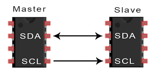
- It has 2 Lines which are SCL (serial clock line) and SDA (serial data line acceptance port)
- CL is the clock line for synchronizing transmission. SDA is the data line through which bits of data are sent or received.
- The master device initiates the bus transfer of data and generates a clock to open the transferred device and any addressed device is considered a slave device.
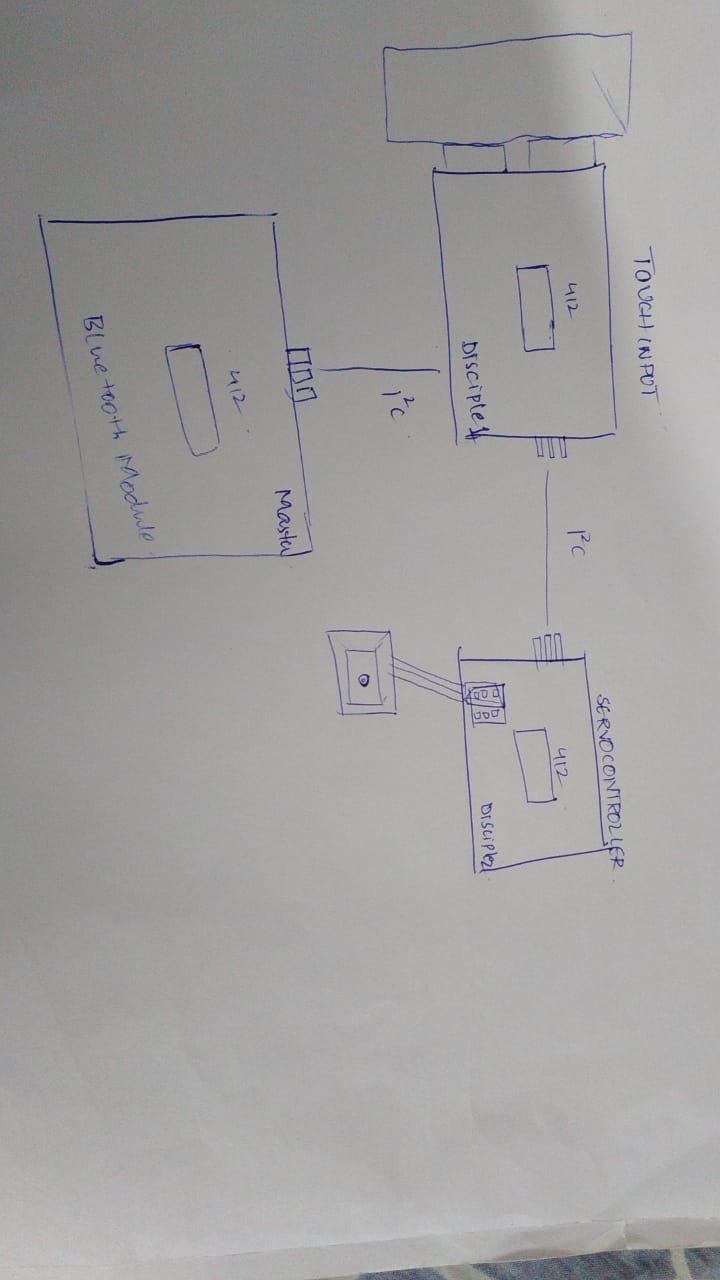
How does it work
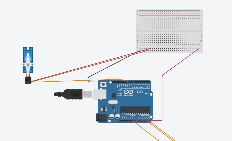
(1) A Master board with a bluetooth module attached.
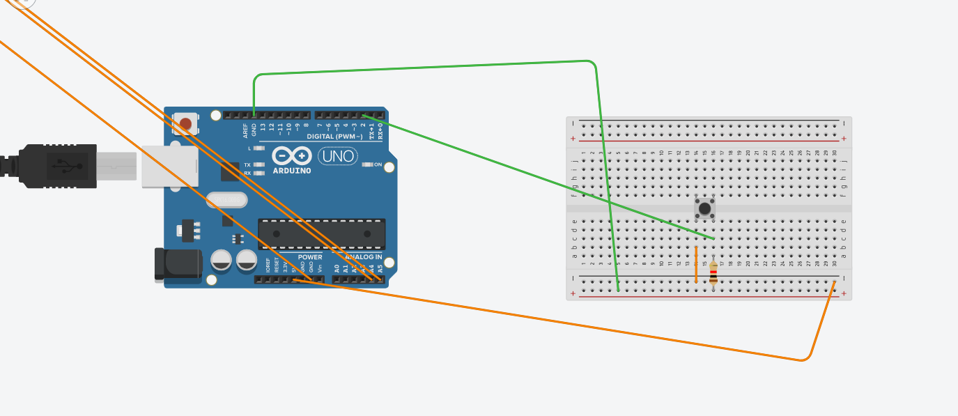
(2) A Disciple 1 board which accepts step-response input
(3) A Disciple 2 board which accepts commands from either the Master 1, or Disciple 1, and run a Servo Motor.
      #include
        #include

        Servo myservo;

        int val;

        void setup()
        {
            Wire.begin(4);
          Wire.onReceive(receiveEvent);
          Serial.begin(9600);
          myservo.attach(9);
        }


        void loop()
        {
          delay(100);
        }


        void receiveEvent(int howMany)
        {
          int x = Wire.read();
          Serial.println(x);
         if (x == HIGH) {
            val = 90;
          }
          else {

            val = 0;
          }
          myservo.write(val);
          delay(15);

        }
      // C++ code
//
#include

int pushbutton=2;

void setup()
{
  Wire.begin();
  pinMode(pushbutton,INPUT);
}

int x = 0;

void loop()
{
  Wire.beginTransmission(4);
  x=digitalRead(pushbutton);
   Wire.write(x);
  Wire.endTransmission();
  delay(500);
}
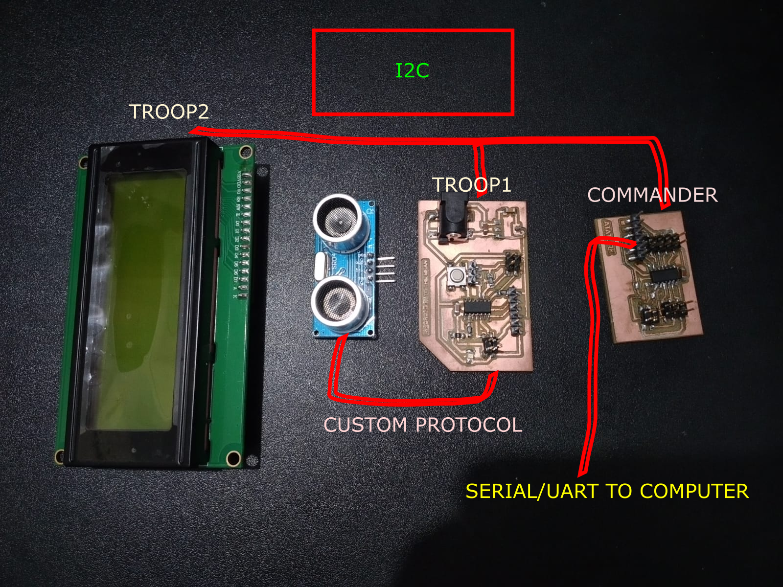
After Reaching The Lab:
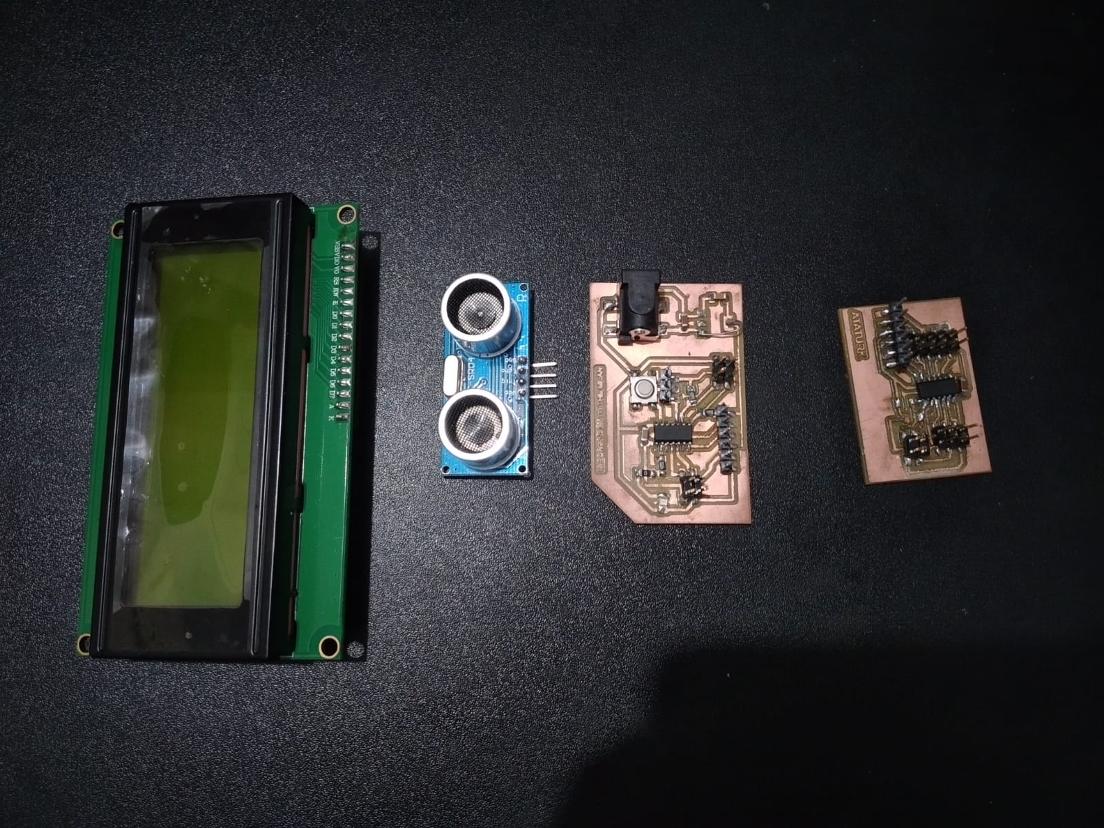
- Commander
- Troop1
- LCD
Commander:
              #include  // Library for LCD
              #include

              LiquidCrystal_I2C lcd(0x27, 20, 4);

              void setup() {
                Wire.begin();
                Serial.begin(115200);

                lcd.init(); //Intialize LCD
                lcd.backlight(); //Switch-On BackLight for LCD
                lcd.home();
                lcd.print("Networking");
                lcd.setCursor(0, 1);
                lcd.print("Communications");
                lcd.setCursor(8, 3);
                lcd.print("~Jai Hanani");
                delay(2000);
              }

              void loop() {
                Wire.requestFrom(8, 3); //Request 3 bytes of data from Troop 1
                int i = 0;
                char x[3];
                while(Wire.available())
                {
                  char c = Wire.read();
                  x[i] = c;
                  i = i + 1;

                }
                Serial.println(x);
                  lcd.clear();
                  lcd.home();
                  lcd.print(x);
                delay(500);
              }
Troop1:
                #include

                int trigPin = 3; //Trig Pin for Ultrasonic Sensor
                int echoPin = 2; //Echo Pin for Ultrasonic Sensor
                int ledPin = 0;

                long duration;
                int cm;

                char cstr[16];

                void setup() {
                  Wire.begin(8);
                  Wire.onRequest(requestEvent);
                  pinMode(ledPin, OUTPUT);
                  digitalWrite(ledPin, HIGH);

                  Serial.begin(9600);
                }

                void loop() {

                  pinMode(trigPin, OUTPUT); //Set Ultrasonic Trigger Pin as OUTPUT
                  digitalWrite(trigPin, LOW); //Write it to LOW
                  delayMicroseconds(2); // Wait for 2mus
                  digitalWrite(trigPin, HIGH); // Write the Trig Pin to HIGH
                  delayMicroseconds(10); // Wait for 10mus
                  digitalWrite(trigPin, LOW);// Write the Trig Pin to LOW
                  pinMode(echoPin, INPUT); //Set Ultrasonic Echo Pin as INPUT

                  duration = pulseIn(echoPin, HIGH); //The duration the echoPin takes to go HIGH in microseconds

                  cm = microsecondsToCentimeters(duration);
                  sprintf(cstr, "%03d", cm);

                  Serial.println(cm);
                  delay(500);

                }

                long microsecondsToCentimeters(long microseconds){
                  return (microseconds / 29.15 ) / 2;
                }

                void requestEvent() {
                  Wire.write(cstr);
                }
Group Assignment:
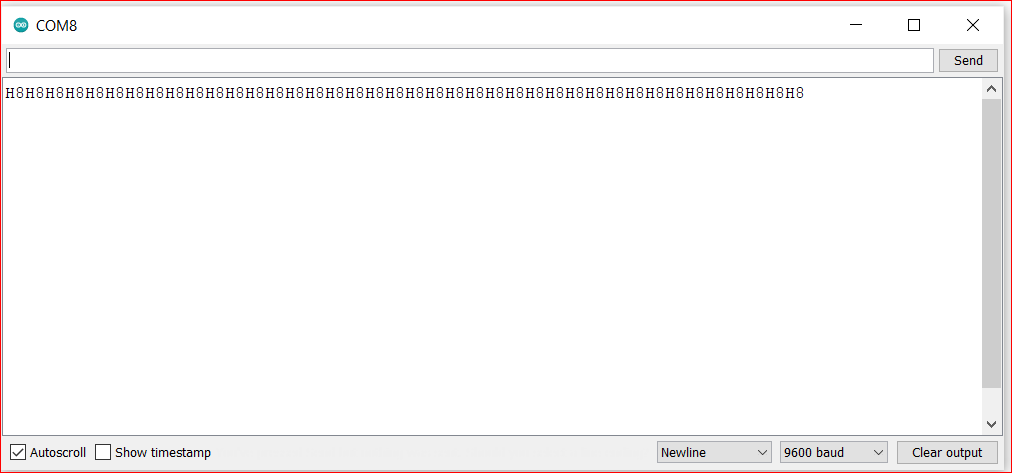
For this Group Assignment, I had to send a message between two projects. I selected Arduino as one board and my custom-made board as the secondary board. I had connected the TX/RX pins of Arduino to RX/TX pins of my board, respectively. The project, here, is to send data between Arduino and My Board and The Computer. The Arduino sends '8' to the Board with an LED blink and The Board checks whether the received message is '8'. If it is '8', The Board replies with Char 'H' coupled with an LED blink.
Arduino Code:
            char incomingByte;

            void setup() {
              Serial.begin(9600);
              pinMode(LED_BUILTIN, OUTPUT);
            }

            void loop() {

                   Serial.write('8'); //Send the letter
                   digitalWrite(LED_BUILTIN, HIGH);
                   delay(1000);
                    digitalWrite(LED_BUILTIN, LOW);
                  delay(1000);

                  incomingByte = Serial.read();
              Serial.print(incomingByte); //Recieve the letter

                }
"The Board" Code:
              const char node = '8';
              char incomingByte;

              void setup() {
                Serial.begin(9600);
                pinMode(0, OUTPUT);
              }

              void loop() {

                  incomingByte = Serial.read();
                  if (incomingByte == node) {
                    digitalWrite(0, HIGH);
                    delay(1000);
                    digitalWrite(0, LOW);
                    Serial.write('H'); //Send H
                  }
                }