Mechanical Design and Machine Design

Week 9 | 24-03-2021

Group Assignment

- Design a machine that includes mechanism
+actuation+automation,
- Build the mechanical parts and operate in manually,
- Actuate and automate your machine,
- document the group project and your individual contribution.

Individual Assignment

Null

Files, Planning, Tools

Files:

Planning:
- Decide the machine-to-be-built,
- Divide the whole group into sub-teams,
- Divide the work for sub-teams,
- Execute..

Tools:
Stepper Motors,
Ultimaker,
Aluminium Extrusions,
Trotec Laser Cutter,
Prusa Printer,
Arduino IDE,
Arduino Nano.


  1. After a long back-forth, our team has decided to replicate CoreXY mechanism.
  2. I am handling the electronics/programming part in the project.
  3. I borrowed a stepper motor from the inventory for experimentation.
  4. I am consulting this instructables article to control the motor: here
  5. I have just learnt about H-Bridge, and the importance of it in driving the stepper motors
  6. I borrowed a CNC plotter that was lying around in my lab.
  7. Firstly, I tried to make one motor move. [Image linked, down below] 
  8. Using Accel Stepper library in Arduino IDE, I made it possible: here
  9. Then, I moved the motor in other axis.
  10. Using Multiple_Stepper component in the Accel Stepper library, I made the two motors move asynchronously.
  11. I wrote some code to move the motors in semi-circular fashion. This is the code:
      // MultiStepper.pde
    // -*- mode: C++ -*-
    // Use MultiStepper class to manage multiple steppers and make them all move to
    // the same position at the same time for linear 2d (or 3d) motion.
    #include
    #include
    // EG X-Y position bed driven by 2 steppers
    // Alas its not possible to build an array of these with different pins for each :-(
    AccelStepper stepper1(AccelStepper::FULL4WIRE, 2, 3, 4, 5);
    AccelStepper stepper2(AccelStepper::FULL4WIRE, 8, 9, 10, 11);
    // Up to 10 steppers can be handled as a group by MultiSteppe
    MultiStepper steppers;
    void setup() {
    Serial.begin(9600);
    // Configure each stepper
    stepper1.setMaxSpeed(100);
    stepper2.setMaxSpeed(100);
    // Then give them to MultiStepper to manage
    steppers.addStepper(stepper1);
    steppers.addStepper(stepper2);
    }
    void loop() {
    long positions[2]; // Array of desired stepper positions
    positions[0] = 1000;
    positions[1] = 50;
    steppers.moveTo(positions);
    steppers.runSpeedToPosition(); // Blocks until all are in position
    delay(1000);
    // Move to a different coordinate
    positions[0] = -100;
    positions[1] = 100;
    steppers.moveTo(positions);
    steppers.runSpeedToPosition(); // Blocks until all are in position
    delay(1000);
    }
  12. Now I am trying to understand G-Code and put it to use for the project. I am consulting this website for that: here
  13. I tried this online G-Code simulator: here
  14. Then I am going through these instruct-able articles of plotters: here, here
  15. I am studying the theory behind the working mechanism of core-xy, from here: COREXY-THEORY
  16. Videos to help you feel the working mechanism in your bones:

  17. Next, I am going through program written by 'lingib', and understand its inner workings, called coreXY_plotter - here
  18. Then, I went through the datasheet for 17HS19-2004S1 motor to figure out the STEPS_PER_MM(an important parameter in the program).
  19. From the documentation for the 17HS19-2004S1 motor, the motor_step_angle is 1.8 degrees
  20. I am using this online calculator to find out the STEPS_PER_MM and NUDGES for my motor and motor_driver - here We are using Pololu DRV8255 motor.
  21. Therefore, 
    • Motor Step Angle : 1.8 degrees
    • Driver Microstepping: 1/16
    • Belt Pitch(The distance between the center of two troughs): 2 mm
  22. I am consulting this article to figure out the G-code for format for circular arcs: HERE
  23. Salient point: G02 code is responsible for commanding the machine to move in clockwise circular arcs. G03 initiates a mode which moves the machine in a counterclockwise circular arc.
  24. Next,I have spent my time understanding how Bresenham's line testing algorithm works from this beautiful article from U of Helsinki: here


  • Final Output:


    Link to our Project Documentation.

  • Mobirise

    Image Description

    Working mechanism behind stepper motor:

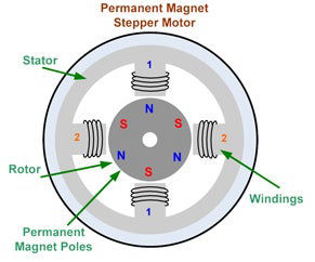
    A stepper motor consists of two main parts, a rotor and a stator. The rotor is the part of the motor that actually spins and provides work. The stator is the stationary part of the motor that houses the rotor. In a stepper motor, the rotor is a permanent magnet. The stator consists of multiple coils that act as electromagnets when an electrical current is passed through them. The electromagnetic coil will cause the rotor to align with it when charged. The rotor is propelled by alternating which coil has a current running through it.

    Mobirise

    Image Description

    Working mechanism behind H-Bridge:

    An H-Bridge is a circuit comprised of 4 switches that can safely drive a DC motor or stepper motor.Unlike a single transistor which only allow you to control the speed of a motor, H-bridges allow you to also control the direction in which the motor spins. It does this by opening different switches (the transistors) to allow the current to flow in different directions and thus changing the polarity on the motor.

    Make a website with Mobirise