Week 6: Electronics Design
In this sixth week of Fab Academy, I need to redraw one of the echo hello-world boards or something equivalent, add (at least) a button and LED (with current-limiting resistor) or equivalent input and output, check the design rules, make it, test it. In the group assignment we need to use the test equipment in your lab to observe the operation of a microcontroller circuit board (in minimum, check operating voltage on the board with multimeter or voltmeter and use oscilloscope to check noise of operating voltage and interpret a data signal). Further learnings from this week are listed below:
- Make some interesting circuit designs without compromising the functionality
- Make mistakes and learn from mistakes and also document the same so that I could save other's time
- Include design files and references
- Design and 3D print a novel product which fits all the assignment criterion
- Take photos of various steps and explain everything in layman's language
- Test the board, load program and troubleshoot if necessary
- Mill the PCB and solder the components without fail
- Demonstrate workflows used in circuit board design.
The following are the softwares that I have used for learning various operations:
- Autodesk Eagle : Ciruit Design
- MIT Mods : Machine Management
| |
|
|---|---|
| Wednesday | Prof. Neil's class on Electronic components, Softwares, Electronics Design |
| Thursday | Understanding Eagle, Oscilloscope, Mods, Modela, |
| Friday | Desigining the PCB & Tracing |
| Saturday | Documentation |
| Sunday | Documentation |
| Monday | PCB Milling and Testing |
| Tuesday | Documentation |
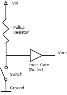
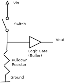
Pull-Up/ Pull-Down Resistors
Pull-up resistors are resistors which are used to ensure that a wire is pulled to a high logical level in the absence of an input signal. Pull-up resistors are not a special kind of resistors; they are simple fixed-value resistors connected between the voltage supply (usually +5V) and the appropriate pin, which results in defining the input or output voltage in the absence of a driving signal. Pull-down resistors work in the same manner as pull-up resistors, except that they pull the pin to a logical low value. They are connected between ground and the appropriate pin on a device.
Resistor Value
The appropriate value for the pull-up resistor is limited by two factors. The first factor is power dissipation. If the resistance value is too low, a high current will flow through the pull-up resistor, heating the device and using up an unnecessary amount of power when the switch is closed. This condition is called a strong pull-up and is avoided when low power consumption is a requirement. The second factor is the pin voltage when the switch is open. If the pull-up resistance value is too high, combined with a large leakage current of the input pin, the input voltage can become insufficient when the switch is open. This condition is called having a weak pull-up. The actual value of the pull-up’s resistance depends on the impedance of the input pin, which is closely related to the pin’s leakage current. However the resistance value for Attiny 44 is specified in its data sheet as 10KOhm to 20kOhm, We have opted 10kohm resistor for the pull-up.(thank you my friend lancy for this valuable informations.)
LED series Resistor value
A light-emitting diode (LED) is a two-lead semiconductor light source. It is a p–n junction diode that emits light when activated. If we apply a current that is greater than the desired value of an led the junction temperature will increase because Heat = I^2 x R x t , (I = current through Led,R = Resistance of conductor, t = time ) .So if the junction temperature increas it may lead to the fast deterioration of the juction or complete breakdown of the device so it is important to maintain the current through the LED. The easiest and simplest way is to use a series resistor.
The formula to calculate the correct resistance to use is R=(Vs-Vf)/I
where Vs is the power supply voltage, e.g. a 9-volt battery; Vf is the LED forward voltage (also referred to as the "voltage drop") across the LED; and I is the desired current of the LED
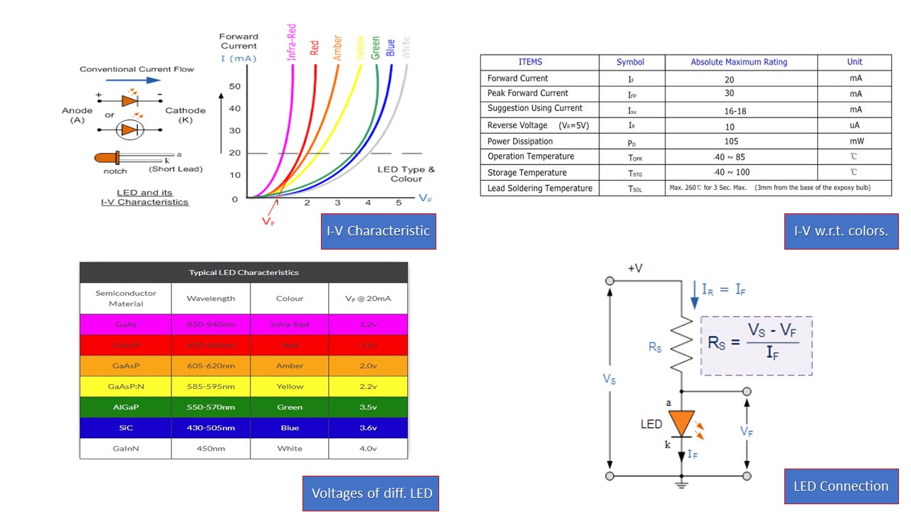
The image also shows the typical I-V characteristics with respect to different colours. From the above table the maximum peak current for an LED is 30 mA and maximum continuous current is 20 mA. So we have to set the LED current to a lower value as prefered in the table we can choose a value in between 16-18 mA. From the graph find the voltage required at the given current lets say the current choosen is 20 mA and led is red, then find projecton of 20mA point from the red curve it will be arround 1.8V . So let as coose 1.8V and 18 mA as the operating condition of our LED.
In the figure there is a typical LED circuit/connection where Rs is the Series resistance, Vs is the source voltage, Vf is the forward voltage of the LED (also referred to as the "voltage drop").
So we have
Vs = Supply voltage =5v
Vf = 1.8V
If = 18mA
So Rs = (5 - 1.8)/(.018) = 177.77
The closest resistor having a greator value than this in our lab is 499 Ohm .
EAGLE is a scriptable electronic design automation (EDA) application with schematic capture, printed circuit board (PCB) layout, auto-router and computer-aided manufacturing (CAM) features. EAGLE stands for Easily Applicable Graphical Layout Editor. EAGLE contains a schematic editor, for designing circuit diagrams. Schematics are stored in files with .SCH extension, parts are defined in device libraries with .LBR extension. Parts can be placed on many sheets and connected together through ports. The PCB layout editor stores board files with the extension .BRD. It allows back-annotation to the schematic and auto-routing to automatically connect traces based on the connections defined in the schematic. EAGLE saves Gerber and PostScript layout files as well as Excellon and Sieb & Meyer drill files. These are standard file formats accepted by PCB fabrication companies, but given EAGLE's typical user base of small design firms and hobbyists, many PCB fabricators and assembly shops also accept EAGLE board files (with extension .BRD) directly to export optimized production files and pick-and-place data themselves. EAGLE provides a multi-window graphical user interface and menu system for editing, project management and to customize the interface and design parameters. The system can be controlled via mouse, keyboard hotkeys or by entering specific commands at an embedded command line. Multiple repeating commands can be combined into script files (with file extension .SCR). It is also possible to explore design files utilizing an EAGLE-specific object-oriented programming language (with extension .ULP). I am very much new to Eagle and I hope to fail and learn to make this software easy for me. At first, I found the select tool to be a bit difficult but practise made it easier. But I am very much scared with autorouting.
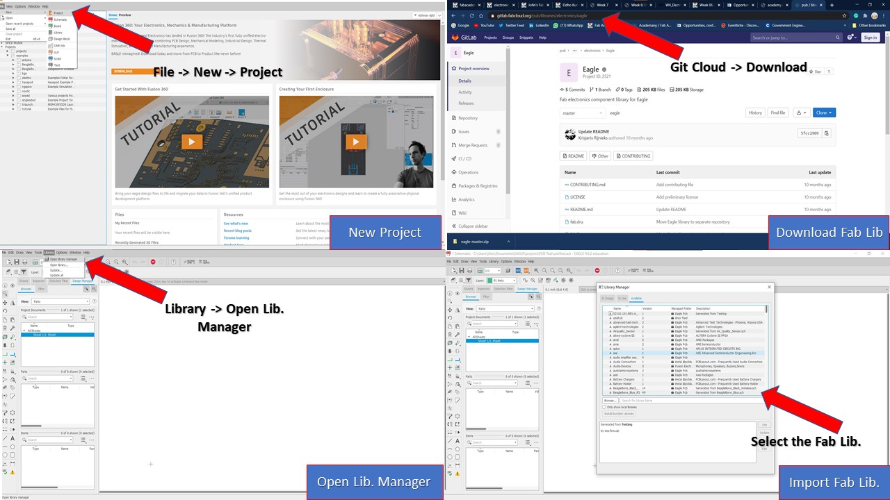
Baby steps with Eagle
To redesign the Hello Board, I first need to install Eagle. Once installed, the first step is to download the Fab Library which contains all the necessary components for the development of the board. You can download the the file by going into Eagle Fab Cloud and downloading it into your PC. After installing the Eagle, first you need to create a new project by going onto New -> Project and naming it. Once you create the project, then right click the project to create a new schematic. Once schematic is opened you need to go to Library -> Open Library Manager and browse the Fab Library. Once you find it, add that library.
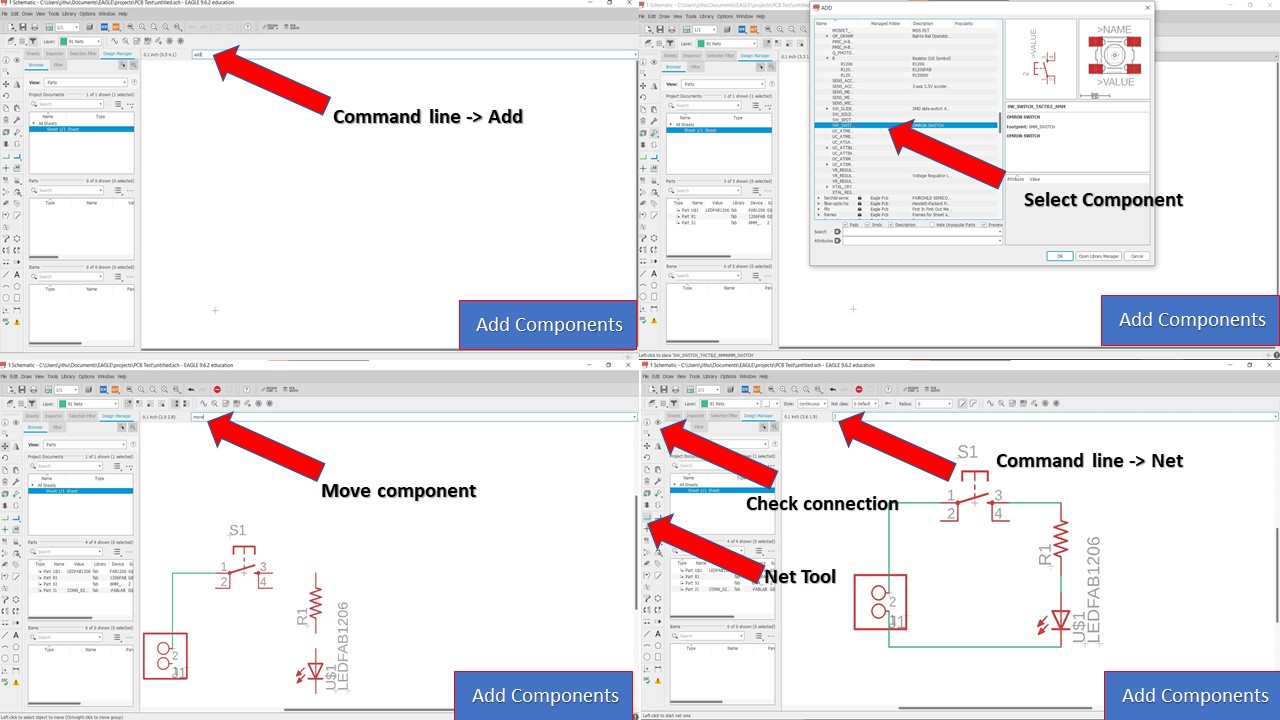
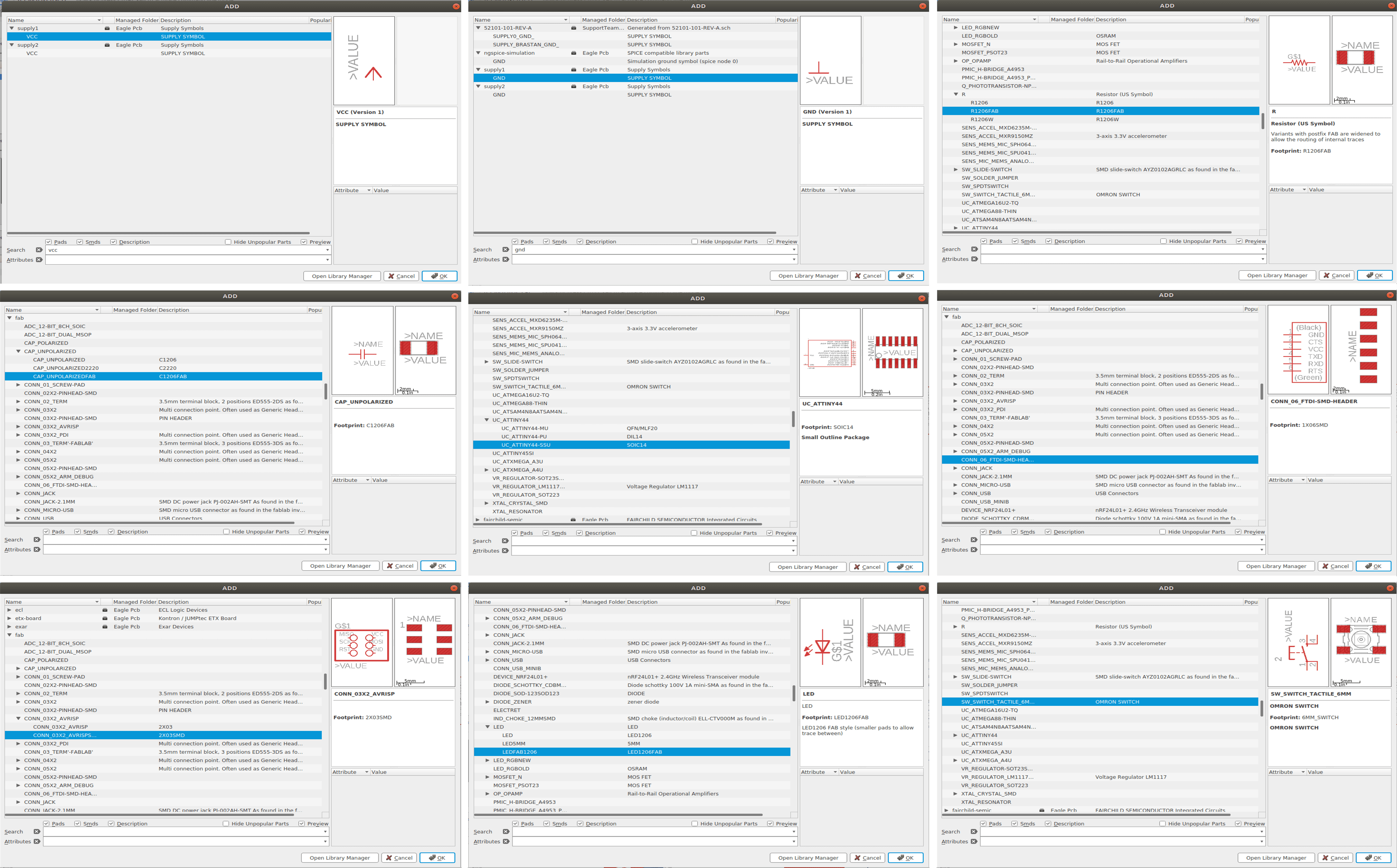
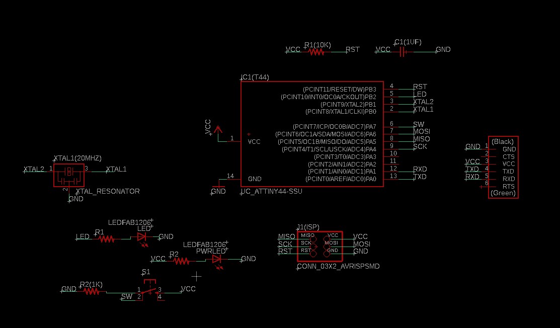
The next step is to insert the components from the Fab Library. For that you need to go to Command Line -> Add and press enter. Then you need to select the components based on the schematic preferred by Fab Academy. Here I have selected ATtiny 44 based board for making the ech hello-world board. Once components are added then you can type "Move" command in command line to move the components and double clicking it to rotate the model. The next step is to connect the components. Always click the cross mark to select and move the components (it's kinda odd to be frank). You can also name the various traces by right clicking and naming it so that it gets automatically connected to the nets with similar names.
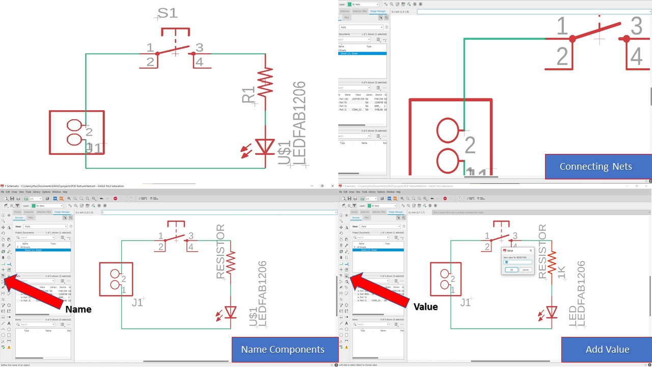
Once you complete the circuit, then you can verify the continuity by using the show connection option which highlights the components connected by the net. You can also provide name to the components by going to Name tool in the tool bar and clicking each components. If you need to provide value to the components like say 1 kOhm for a resistor then you need to
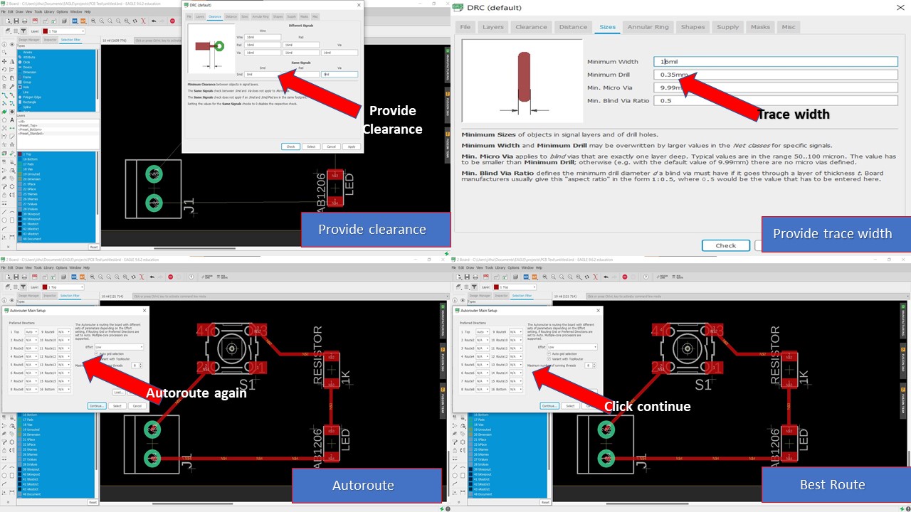
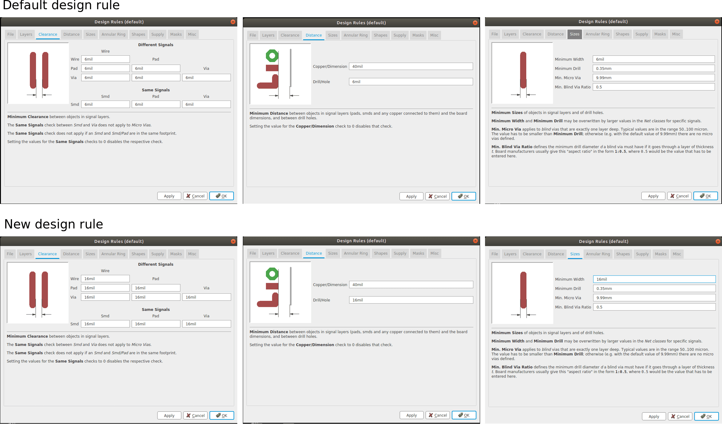
The next step is to switch to the board by going onto the SCH tool. Once you click that then you are greeted with a layout where you can reaarange the components depending upon your wish. Once you complete the arrangement you can click the autoroute switch from the tool bar and traces will be generated. WAIT A MINUTE, how can we ensure that the PCB miller is capable of milling the traces for the random value that we have provided. Here comes the first mistake part, you always need to provide the width and clearance of the trace before autorouting. It can be done by typing the DRC command in the command line.
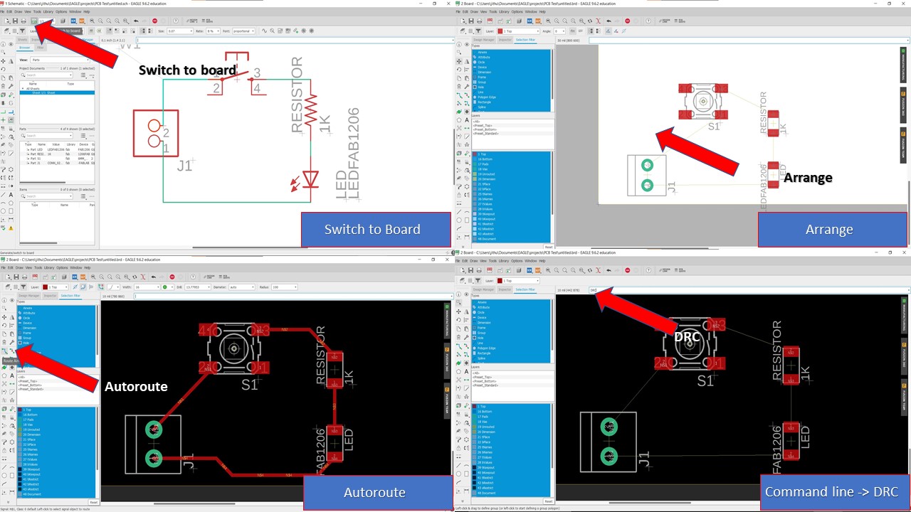
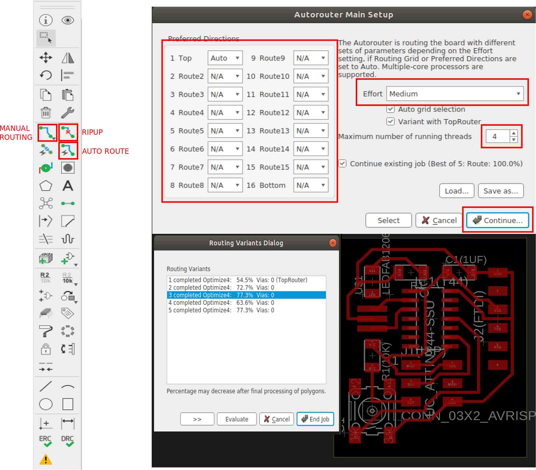
Now you need to provide the clearance and trace width. I had provided it as 16mil based on the accuracy of milling machine. Now you can close that window and click autoroute again to complete the traces. You can also select from various PCB traces and try to take the once with maximum optimization.
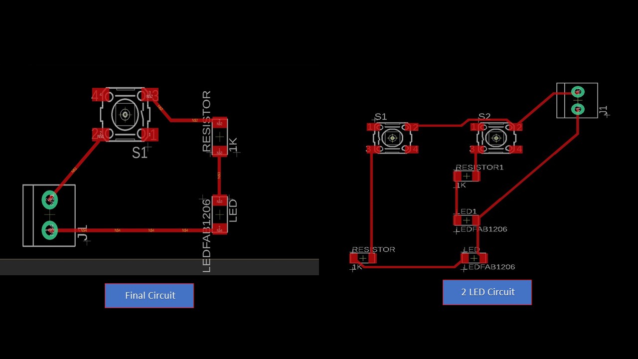
These are the final traces of the test PCB circuit. I had also tried out a 2 LED Circuit for fun. The next step is to actually design the eco hello board.
PCB Circuit Desigining of eco hello-world board
Similar to the previous circuit, you first need to create a new project. Open a new schematic. After adding the components, connect them using the "wire" option. Sometimes, connections get messy; so as optimization, name your connections you want to connect together using same names and you'll find eagle asking you if you want to connect them; click "Yes". For that, use "Name" command. This is will make your schematic look a little bit neat, and it will be more organized. Finally, to avoid confusion, add "label" to connections.
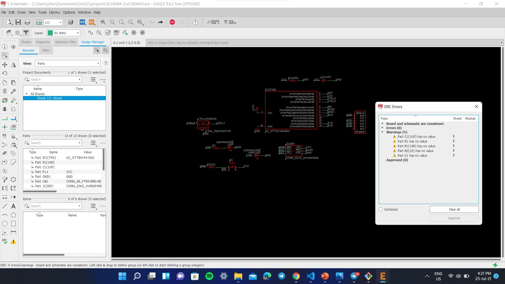
In this step, I had also performed an ERC check and the image is given below
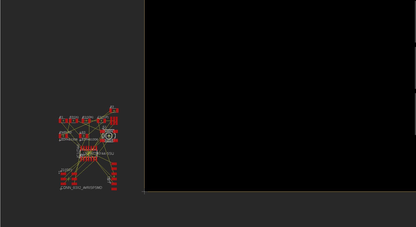
Then you need to place the components away from each other and checked whether the airwires cross each other. You need to rotate and move the components so that there is minimum crossing of airwires. As per the default setting the widths are set to 6mil. This thickness cannot be achieved using our Milling machine. The design rule can be changed from the 'Design Rule' in the 'Edit' option on the taskbar.
For routing the connection I used the 'AUTO ROUTE' tool. I got 92.6% completely optimized. But here comes the tricky part. Even after routing The rest of the connections could not be routed because the airwires are overlapping or moving from one end to other end crossing over some components. This complexity of the circuit can be optimized by connecting the airwires to different legs of the components. I had tried plethora of times to reroute the same but still couldn't get 100% optimization. I didn't wan to use a zero resistor nor a jumper wire so, I kept of trying again. After a lot of attempts with the advice from my classmate Saheen, I was able to finallu obain a 100% optimized trace without using any jumper/zero resistor.
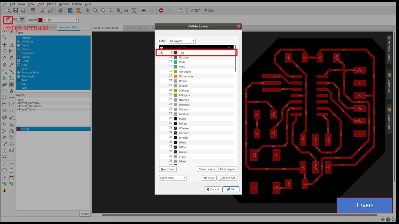
The below image shows the final optimized circuit. The writings on the board design are for our understanding, These writtings must be eliminated before we give it for milling. So for eliminating the writings go to 'LAYERS SETTINGS' and on the 'VISIBLE LAYERS' window enable only the Top layer for the traces.
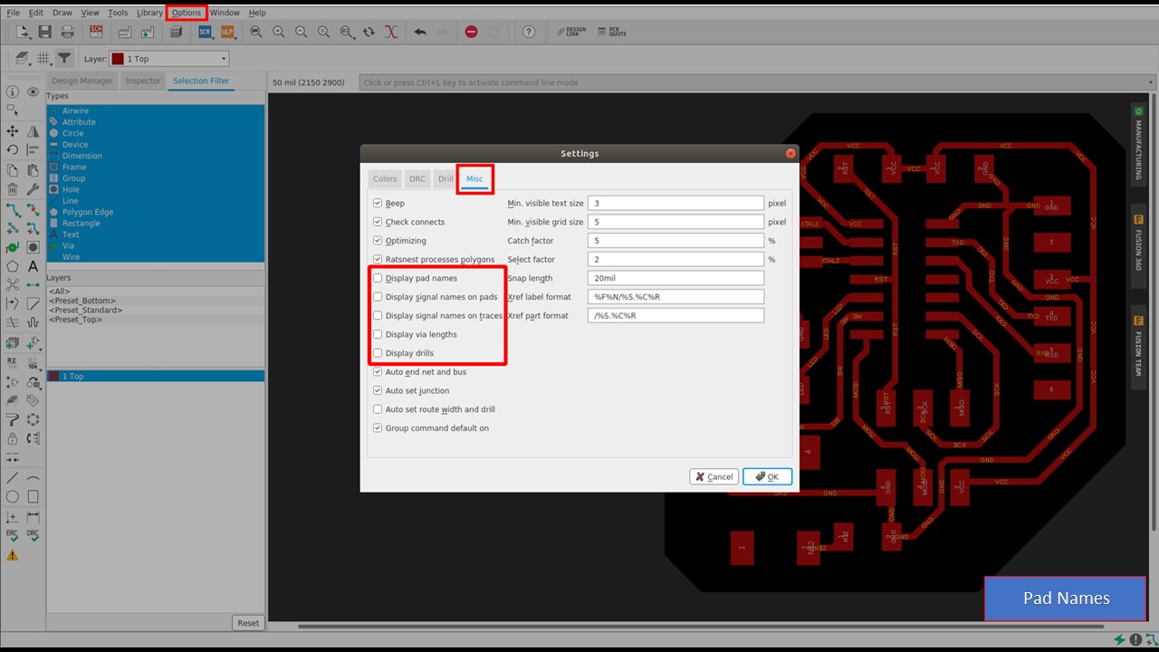
To disable the 'PAD NAMES' and 'SIGNAL NAMES' on the board design, go to 'OPTIONS' on the taskbar and select 'SETTINGS'. On the 'SETTINGS' window click on 'MISC' and disable the PAD NAMES and SINGNAL NAMES as shown.
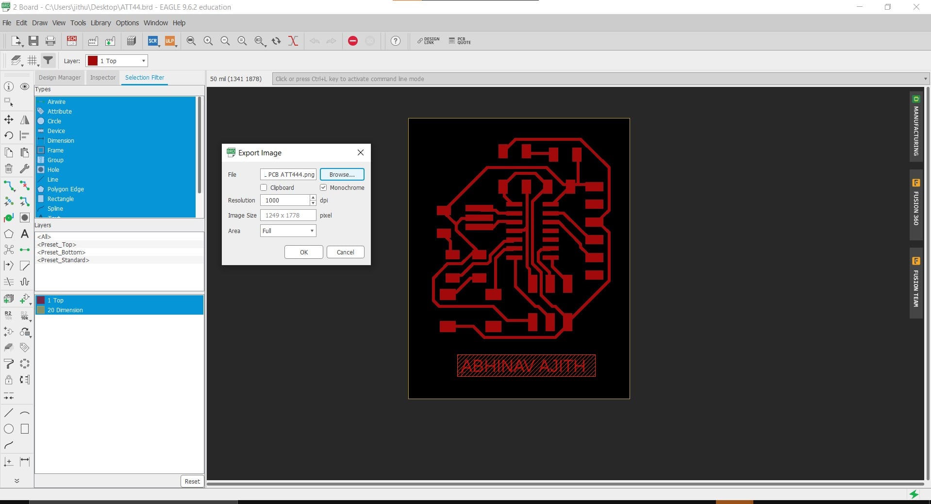
To export the file design as png file, Go to 'FILE' on the taskbar and click 'EXPORT' and select 'IMAGE'. Then a window opens and browse the destination, make it monochrome and change the resolution to 1000dpi.
The final PCB of Echo Hello- World Board
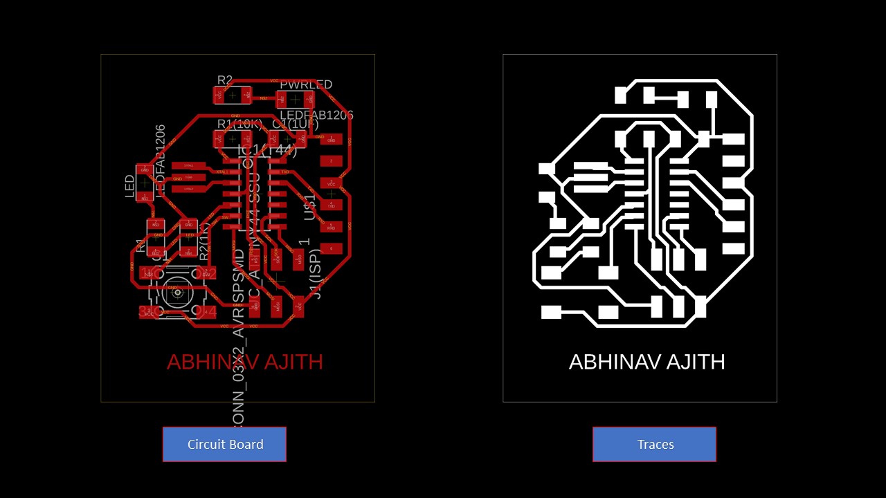
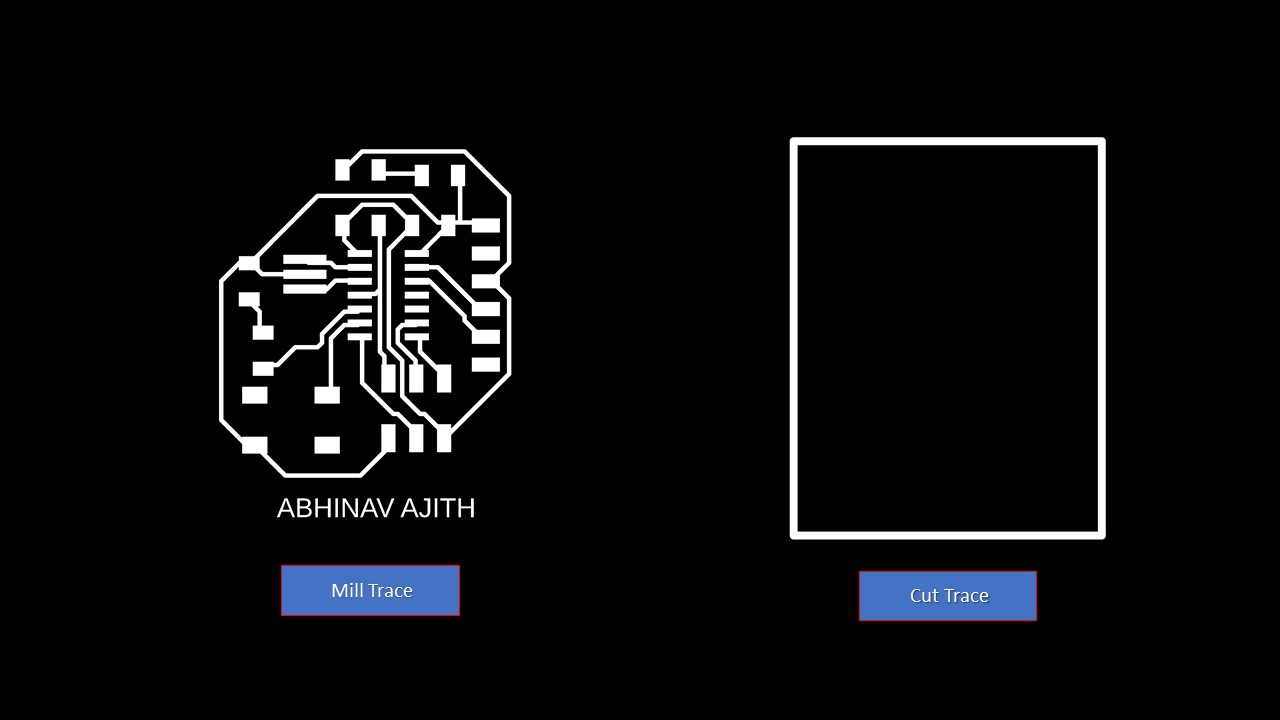
These are the milling and cutting traces of the board
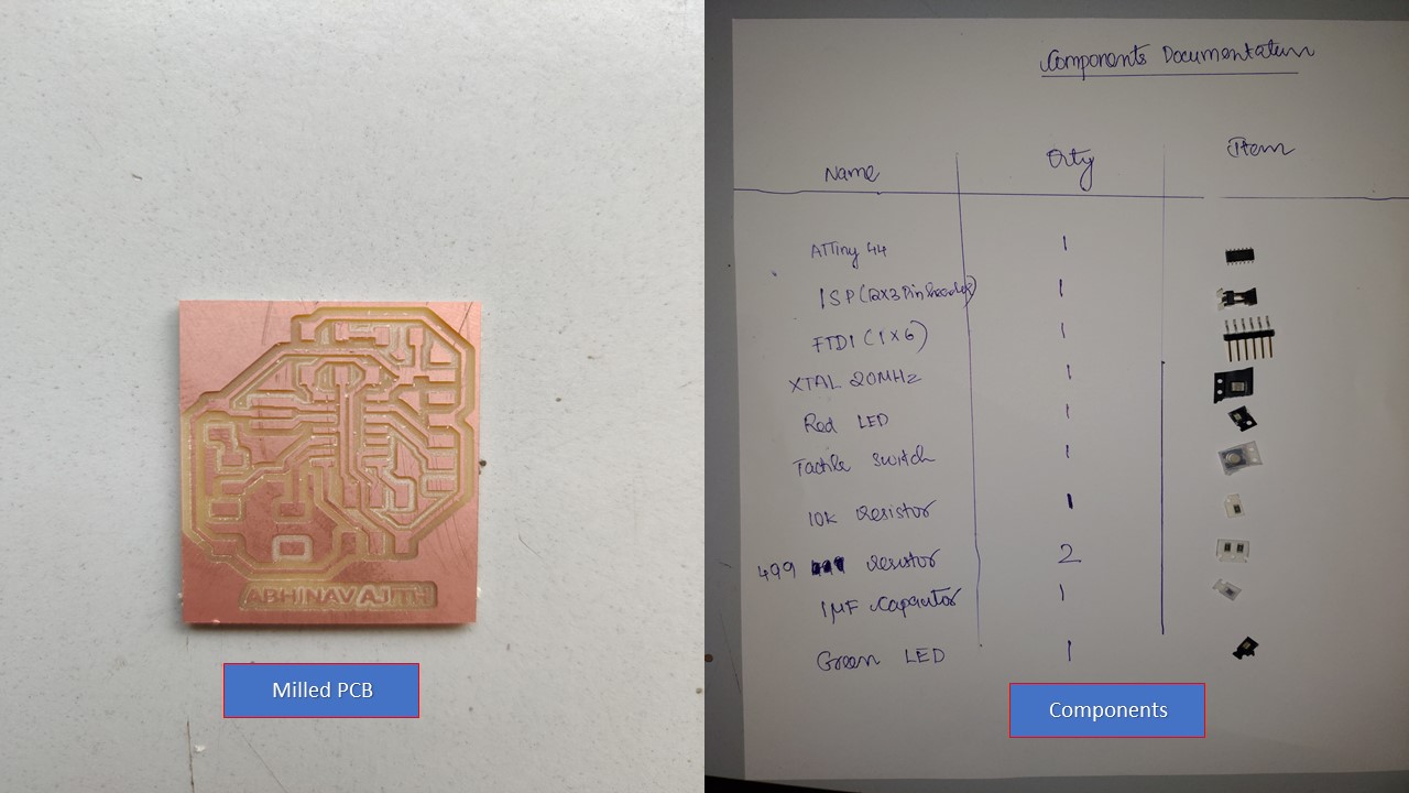
Milling the PCB using Modela PCB Milling Machine
Refering to Week 4, I had milled the PCB board. The components used are depicted below:
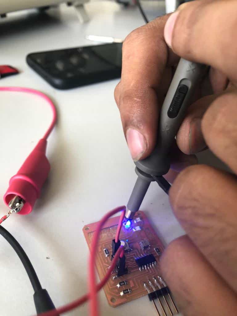
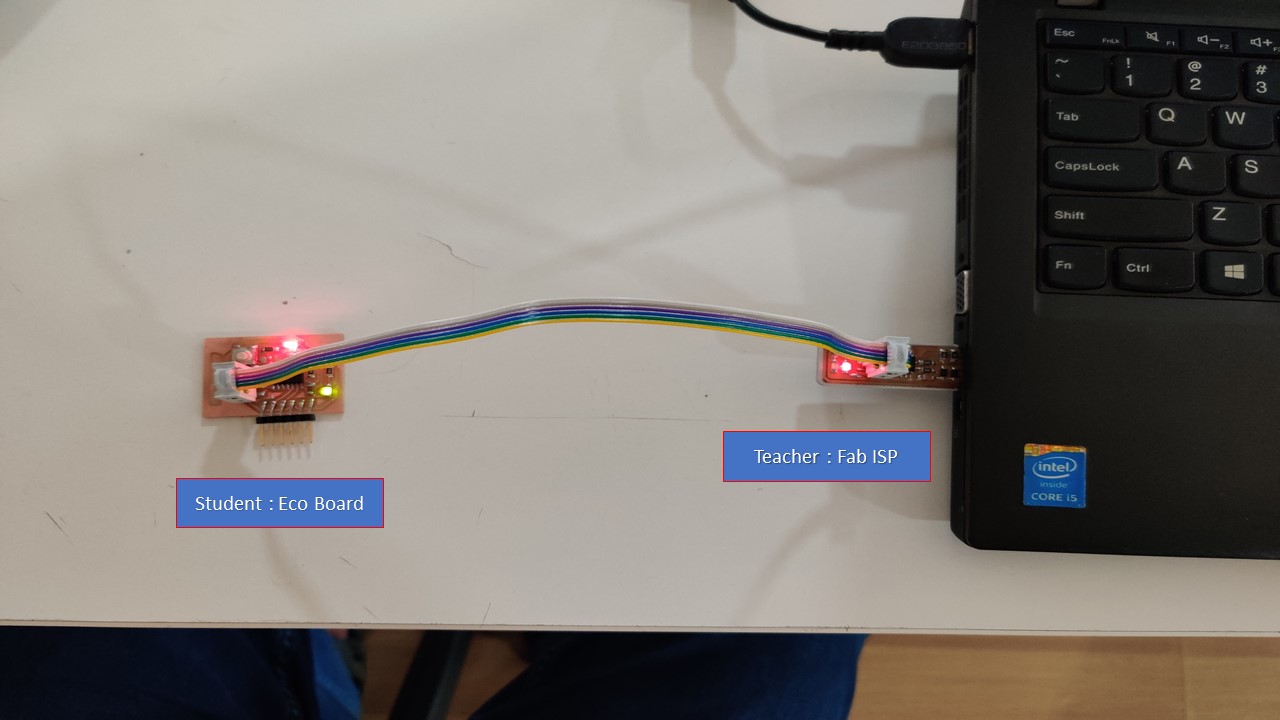
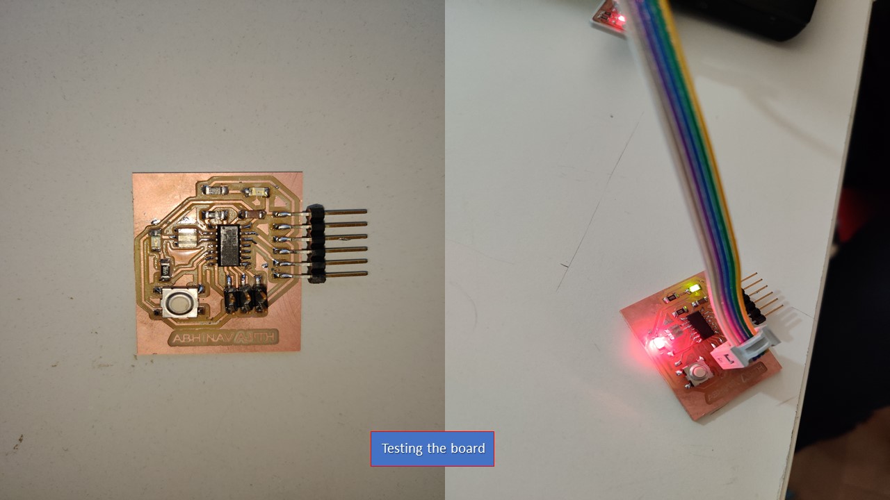
Testing the Board
For testing the "Hello Echo board" I connected it to the computer using the "Tiny ISP micro-controller" made during Electronics Production week. Make sure that the ground (GND) of both the boards are connected to each other.
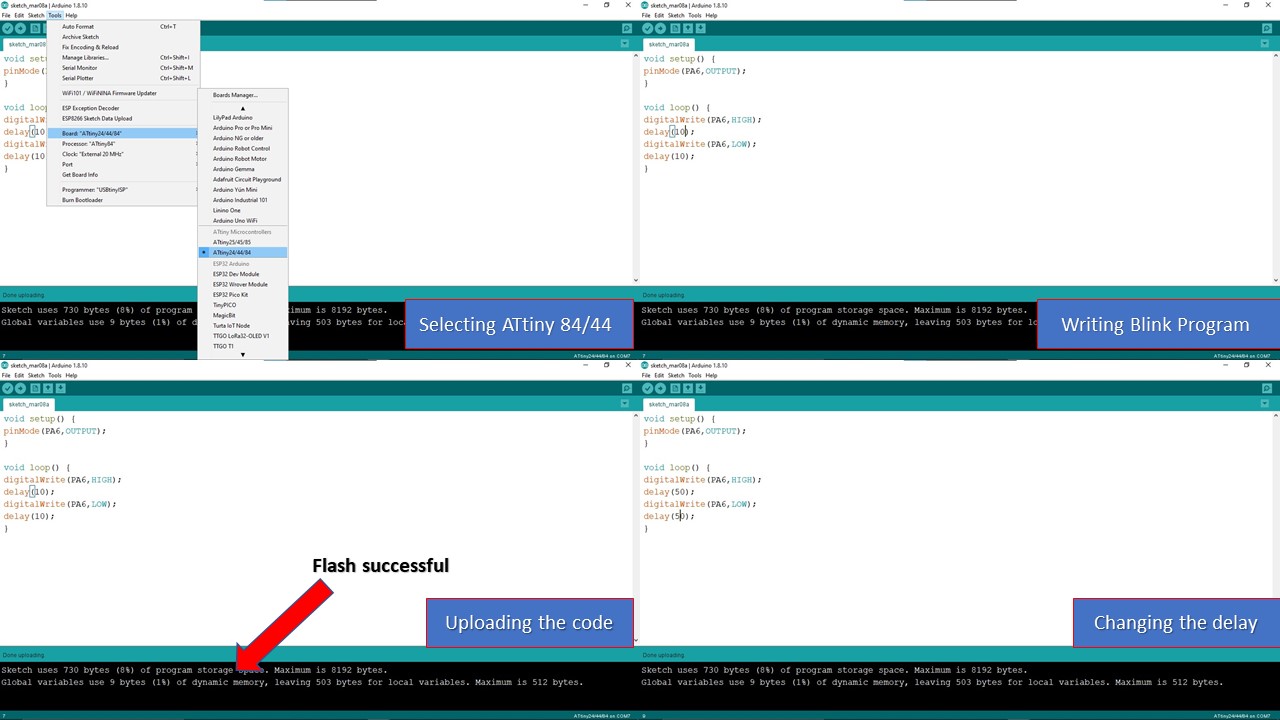
Coding using Arduino IDE
First you need to install the Arduino, then you need to select ATTiny 84/44 from Tools section in menu bar. The next step is to write the program, here I had used a simple program that makes the LED blink. Next you need to run and upload the program. The code flashed successfully but LED didn't blink. To troubleshoot, I had tried to change the port number, test the continuity but still didn't work. Finally, I tried to bypass the 5th pin in microprocessor by connecting the LED to 7th pin. Hurray, it worked. I think the 5th port (PB2) or the firmware may have caused the problem. The testing is shown below:
Update on troubleshooting:
There was no issues with pin number 5 (PB2), the real issue was that since I used Arduino IDE the pin number ordering according to it was different. When I replaced PB2 instead of pin number 8 the board worked perfectly without any errors. My friend Saheen helped me with the troubleshooting.
This week's assignment was to use the test equipment in your lab to observe the operation. So let's meet with the electronics equipments.
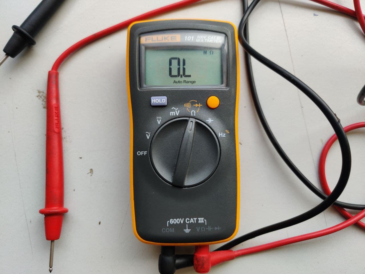
FLUKE 101 Pocket Digital Multimeter
A multimeter is a tool for testing different parameters of an electronic circuit board. Here are the tests which can be conduced using a multimeter:
- Voltage
- Current
- Continuity
- Resistance
- Frequency
- Capacitance
Specifications:
- V AC Range: 600.0 V
- V DC Range: 600.0 V
- Ohms Range: 40.00 MΩ
- Capacitor: 100.0 μF
- Frequency: 100.0 kHz
- Size: 130 mm x 65 mm x 27mm
Using multimeter we had checked the voltage and got a voltage of 5.35V.
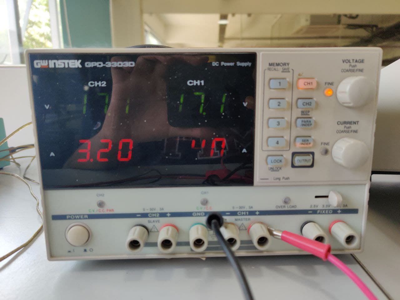
INSTEK GPD-3303D Power Supply
Instek GPD-3303D is a Multiple Output Programmable Linear D.C. Power Supply. The GPD-X303 Series offers digital panel control, large display, bright LED indicators, high output resolution, 4 sets of setup memory, USB remote control and smart cooling fan control. Additionally , the GPD-X303S Series provides easy operation , a wide selection of panel setting and operation.
Features:
- 2/3/4 Independent Isolated Output
- 4 LED Display Sets: 3 digits after decimal point
- 1mV/1mA(GPD-2303D/GPD-3303S/GPD-4303S)
- 100mV/10mA(GPD-3303D)
- 4 Sets Save/Recall
- Output on/off
- Tracking Series and Parallel mode
- USB Standard Interface
- Labview driver
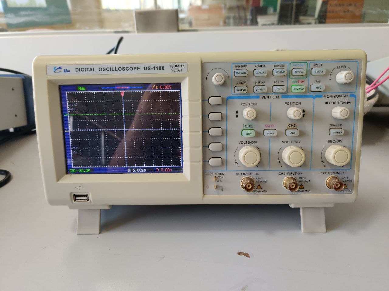
UNISOURCE DS-1100 100 MHZ, 2 CH, Digital Storage Oscilloscope
The digital storage oscilloscope is an instrument which gives the storage of a digital waveform or the digital copy of the waveform. It allows us to store the signal or the waveform in the digital format, and in the digital memory also it allows us to do the digital signal processing techniques over that signal. The maximum frequency measured on the digital signal oscilloscope depends upon two things they are: sampling rate of the scope and the nature of the converter. The traces in DSO are bright, highly defined, and displayed within seconds.
Features:
- 100 MHz bandwidth, 1 M Memory
- USB storage, RS232C & J45 interface
- 4000 point record length for each channel
- Multi-waveforms math, FFT Function
- Cursor & Track measurement
- Waveform Record & Recall, Trigger Mode for Edge, Video, Pulse Width, Slope & Alternate
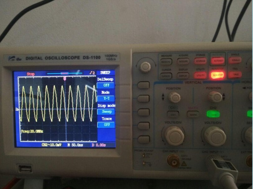
Here we used oscilloscope for checking the frequency generated by the Resonator and got 20MHz as the frequency.
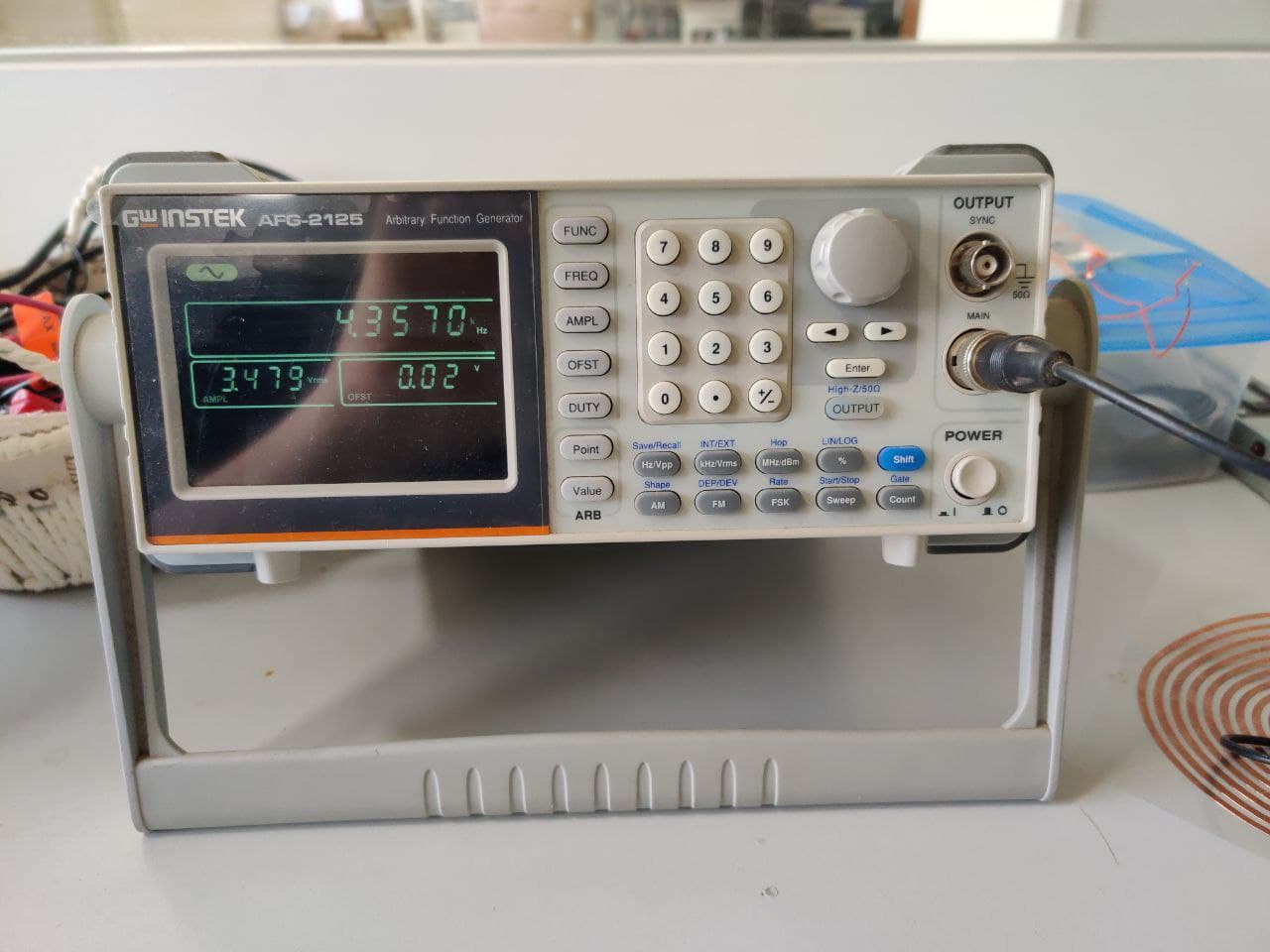
AFG-2100/2000 SERIES ARBITRARY FUNCTION GENERATOR
A function generator is a specific form of signal generator that is able to generate waveforms with common shapes. Unlike RF generators and some others that only create sine waves, the function generator is able to create repetitive waveforms with a number of common shapes. The AFG-2100/2000 Series Arbitrary Function Generator is a DDS (Direct Digital Synthesized) based signal generator designed to accommodate the Educational and Basic Industrial requirements for an accurate and affordable signal source covering the output of Sine, Square (Pulse), Ramp (Triangle), Noise and Arbitrary waveforms.
Features:
- 0.1Hz to 25MHz with in 0.1Hz Resolution
- Sine, Square, Triangular, Noise and Arbitrary Waveform
- 1% ~ 99% adjustable duty cycle for Square Waveform
- Waveform Parameter Setting Through Numeric Keypad Entry & Knob Selection
- Amplitude, DC Offset and Other Key Setting Information Shown on the 3.5" LCD Screen Simultaneously
- AM/FM/FSK Modulation, Sweep, and Frequency Counter Functions (AFG-2100 only)
- PC Arbitrary Waveform Editing Software
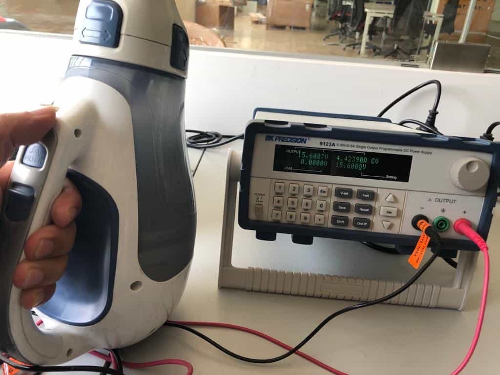
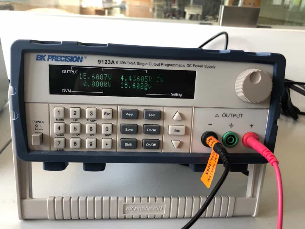
BK PRECISION 9123a series Programmable DC Power Supply
The 9120A series are laboratory grade, programmable DC Power Supplies providing great performance and features not found in other supplies in this price category. The power supplies were designed to meet the needs of today's applications in R&D design verification, production testing or university labs that require clean and reliable power, high resolution/accuracy and fast transient response time.
Features:
- SCPI compatible
- Communicate via USB Interface, using included USB to TTL serial converter cable
- Compact size for bench use or rack mountable (2U x 1/2U size)
- Discrete Fault Indicator/Remote Inhibit (DFI/RI). Useful for turning multiple power supplies On/Off simultaneously
- Application Software for front panel emulation and simple test sequence generation included
- Sheathed banana plug terminals for safety