Week 4: Electronics Production
What should I do this week?
In this forth week of Fab Academy, I need to make an in-circuit programmer by milling the PCB and then program on it and finally test it. Like last week, there are both individual as well as group assignments. The learning outcome of this week are:
- Understanding the PCB machine and tools, characterizing the design rules of PCB production.
- Getting familiar with SMD components and make an in-circuit programmer by milling and stuffing the PCB
- Work as a group, get my hands dirty by using soldering gun & hot air gun
- Need to include orginal files, analyze various parts if possible & explain my learnings in layman language
- Try to fail asap and learn from failures and document those also thereby helping others to reduce mistakes and prevent time loss
- Understand the software installation, test Fab ISP, and include a hero shot of the board
- Learn PCB design software if possible and add that to my skillset which I am presently poor at
- Try not to break the bit and finally, enjoy this week
The following are the softwares that I have used for learning various operations:
Week 4: Action Plan
| |
|
|---|---|
| Wednesday | Prof. Neil's class, Electronics Production, List of Components, Type of bits used, Fab ISP, Flexible circuits & Completed first review with Prof. Neil |
| Thursday | Research on ISPs |
| Friday | Research on various soldering processess |
| Saturday | Reading archives |
| Sunday | Reading archives |
| Monday | PCB Milling |
| Tuesday | Soldering, Testing and the day with most failures as of now |
What exactly is an ISP?
I am a bit afraid for this week since I am a Mechanical Engineer by education and I don't have much experience in fabricating a mini programmable board, but I will take this as a challenge to learn the skill. Before going to the fabrication let me simplify the fancy terms that the geeky electronic grads use. In-system programming (ISP), also called In-Circuit Serial Programming (ICSP), is the ability of some programmable logic devices, microcontrollers, and other embedded devices to be programmed while installed in a complete system, rather than requiring the chip to be programmed prior to installing it into the system. To program a chip, we will need a special programmer which reads commands from USB to drive the SPI lines to program the chip. SPI stands for Serial Peripheral Interface and is a way for microcontrollers to communicate with each other or with the outside world.
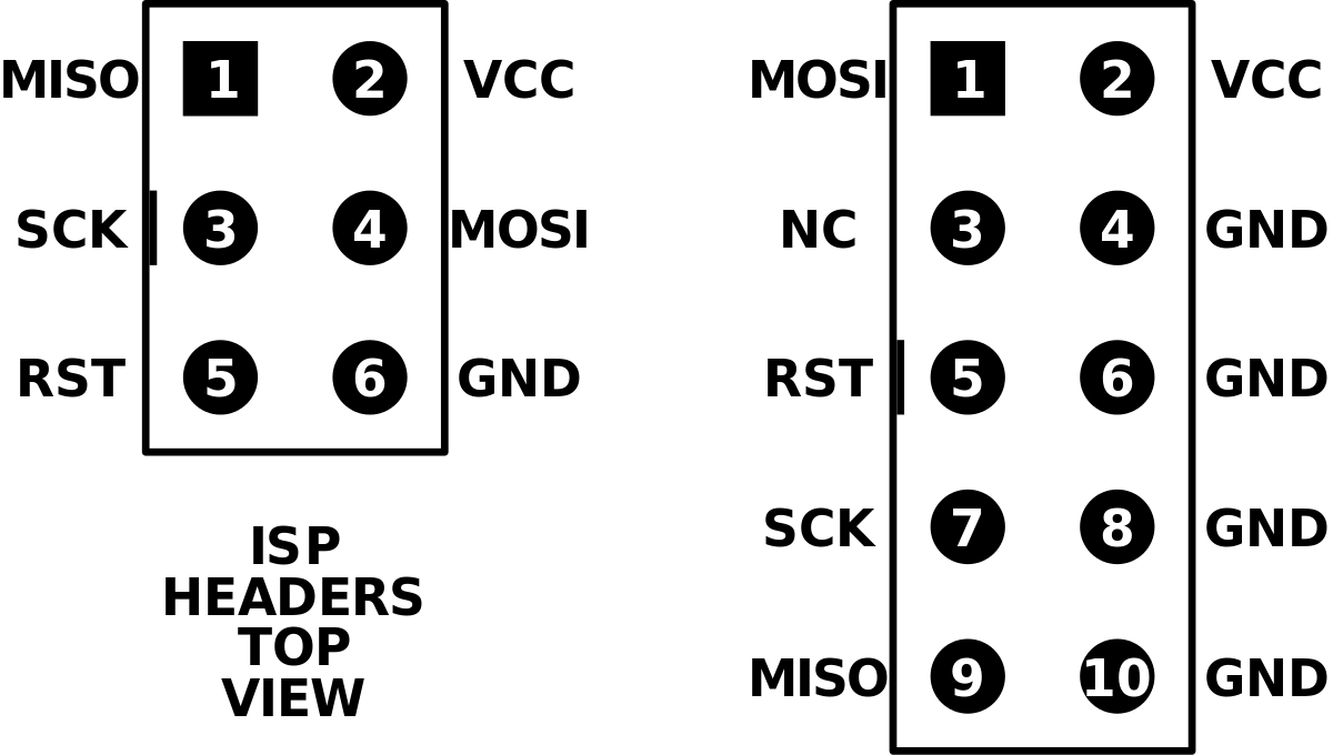
| Name | Abbreviation |
| MISO | Master In Slave Out |
| VCC | Positive Voltage |
| SCK | Serial Clock |
| MOSI | Master Out Slave In |
| RST | Reset Pin |
| GND | Ground |
From the above terms : MISO, MOSI & SCK are the most important ones:
In SPI system , there will be a main module acting as a Master and peripheral acting as Slave. When master need to send some data/need to communicate with slaves, the MOSI channel will be active based on the SCK(Serial Clock), so the communication will happen in given clock time , all the slaves will act as a Input and Master act as Output so the Master can give instruction,like this if the slave need to communicate to the Master they can use MISO that's means the Master can act as Input and Slaves will act as Output, therefore Slave can give feedback to the Master.
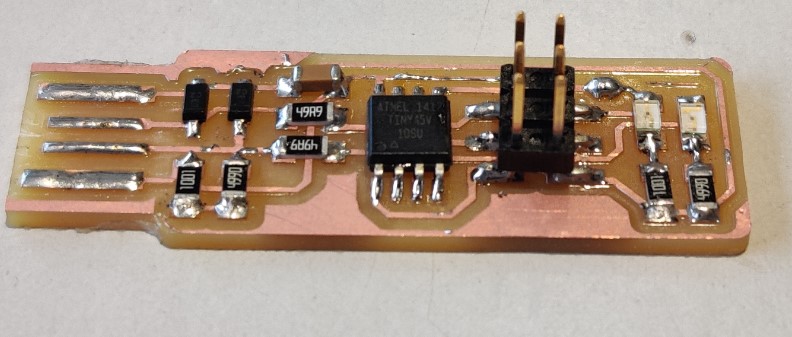
FabTinyISP The FabISP is an in-system programmer for AVR microcontrollers, designed for production within a FabLab. It allows you to program the microcontrollers on other boards you make. There are different versions of ISP's available in the archieve but I selected Brians Version of Fab ISP called "FabTinyISP". It is a ATtiny45 based board having high-performance, low-power Atmel 8-bit AVR RISC-based microcontroller combines 4KB ISP flash memory, 256-Byte EEPROM, 256B SRAM, 6 general purpose I/O lines, 32 general purpose working registers, one 8-bit timer/counter with compare modes, one 8-bit high speed timer/counter, USI, internal and external Interrupts, 4-channel 10-bit A/D converter, programmable watchdog timer with internal oscillator, three software selectable power saving modes, and debugWIRE for on-chip debugging. The device achieves a throughput of 20 MIPS at 20 MHz and operates between 2.7 - 5.5 volts.I choose Brian's verson because this design doesn't have any clock circuits and additional LED's are there to indicating the status of the board while programming.
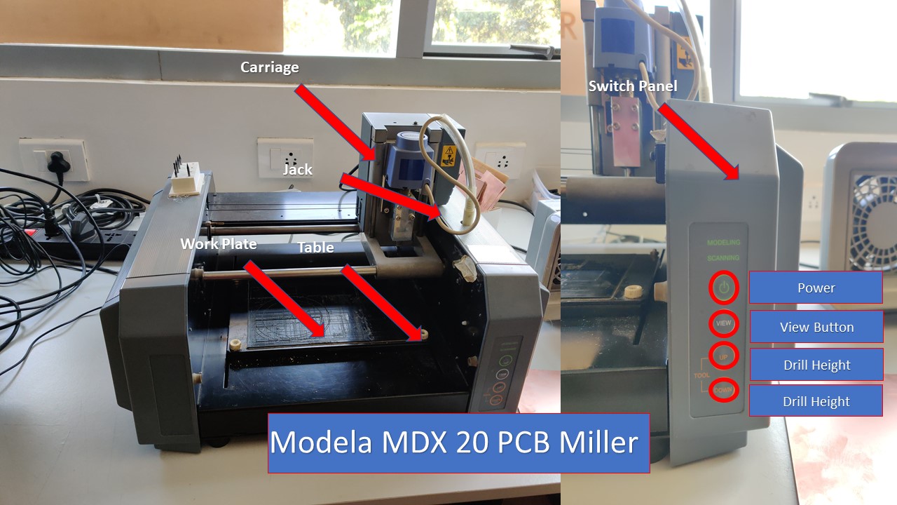
PCB Milling using Modela MDX20 Machine
The Roland Modela MDX-20 is a small milling machine and a 2 1/2D precision scanner.This machine is mostly used for milling circuit boards, though it can also mill in other soft materials like machinable wax. For milling circuit boards you should export you design into a black&white monocroome png. For milling out 3 dimensional molds you should export your design as .stl. The second use of this machine is scanning. It uses a thin needle to gently touch the object and calculates from this a 2 and a half dimensional model. Though slow at processing, it can create a high detailed model. We use the fab modules to give commands to the Modella and run the cutting program. This machine is very delicate and the bits are very fragile, take care in removing the milling cutters and correcting the zero setting. Modella MDX 20 behaves like an ordinary 3-Axis CNC machines, Each axis is driven by a stepper motor and the cutting program tells the machine where to go by giving coordinates to the machine in real time. We have two milling processes in cutting a PCB, The first one is milling the traces to get the circuit board pattern, and the second is cutting out the board from the base material. For milling traces, we use the 1/64th inch (0.4mm) bit and for cutting 1/32th (0.8mm) inch bit. The Modela MDX20 is a Desktop 3D scanning and Milling machine by Roland. Easy to use,compatiable with popular softwares, powerful and can directly connect to the computer via RS232C cable.
| Software | Inkscape + MIT Mods |
| Work area | 203.2 x 152.4 mm |
| Spindle speed | 6500 rpm |
| Material | FR-1 Printed Circuit Board 75 x 50 mm |
| Tools Used | Milling bit 0.4 mm (1/64”); Milling bit 0.8 mm (1/32”) |
Fabrication of FabTinly ISP
It is a ATtiny45 based board having high-performance, low-power Atmel 8-bit AVR RISC-based microcontroller combines 4KB ISP flash memory, 256-Byte EEPROM, 256B SRAM, 6 general purpose I/O lines, 32 general purpose working registers, one 8-bit timer/counter with compare modes, one 8-bit high speed timer/counter, USI, internal and external Interrupts, 4-channel 10-bit A/D converter, programmable watchdog timer with internal oscillator, three software selectable power saving modes, and debugWIRE for on-chip debugging. The device achieves a throughput of 20 MIPS at 20 MHz and operates between 2.7 - 5.5 volts.I choose Brian's verson because this design doesn't have any clock circuits and additional LED's are there to indicating the status of the board while programming. I didn't design the ISP instead, I am taking from older design provided by the Fab Foundation called FabTiny ISP. FabTiny ISP is the one of the provided designs to mill out the pcb and also learn SMD soldering. The schematic of the ISP is provided below:
The following are the steps involved to setup the PCB milling machine
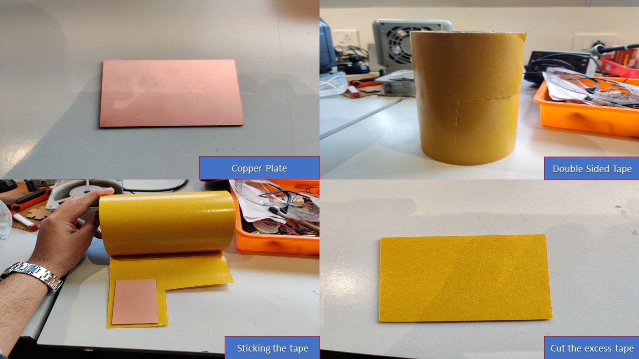
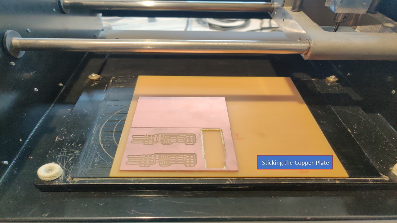
The first step is to place the copper plate on the sacrificial layer of the machine. Then using double sided tape, you have to stick the copper plate inorder to prevent movement during the work. While doing This you need to make sure that the whole milling portion of the PCB is fixed to the table with the tape, if not the PCB may miss align and may damage the cutting bit or the PCB itself. Make sure no air bubbles are present.
The next task is the load the milling bit for tracing the circuit. For that you have to use 1/64 inch milling bit and this step is the most tedious and expensive one. The bit is made of carbide and first of all it's hard but brittle so a slight mistake can cost you anywhere around $50 so be "careful". Now you need to use an L-key/Allen Key to tighten/release the screw from the chuck.
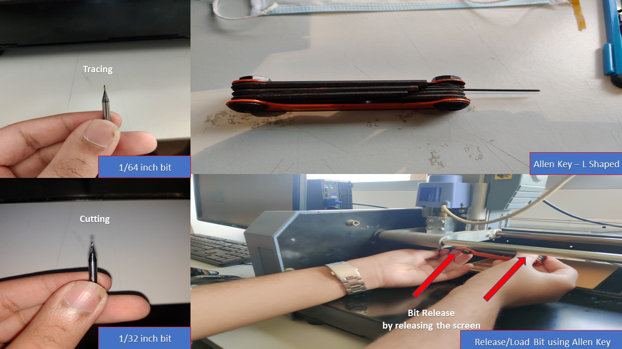
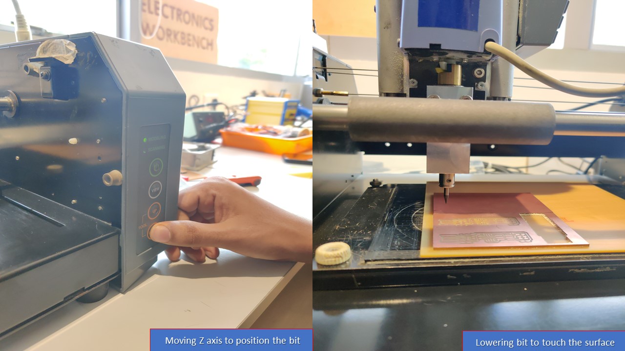
There are several ways to set the Z- value correctly but here I will show you the easiest & most efficient way to do it. These are the steps involved:
- Raise the Z axis to the top
- Release the chuck using the L-key
- Insert the 1/64 inch milling bit a little more in to the chuck
- Tight the screw
- Down the z axis close as possible to the bed using the buttons from control panel
- Unscrew the chuck and release the bit
- Slightly press the bit close to the bed and tight the chuck screw
- Now you are good to go!
Precautions while conducting the previous steps
- Always double check your cutting speed and depth before cutting.
- Never click move to Xmin and Ymin, when you don’t know the z value. The tool might hit the bed and break.
- When setting the zero on Z-axis, tighten both screws of the tool holder properly. We broke one bit because the tool was not fit correctly, it slipped, dug into the board and broke
- Be careful when clicking move to Xmin and Ymin after setting zero position on Z-axis, If there is some machine error, the tool will hit the bed and break.
- Never touch the Up and Down button when changing the tool.
- When changing the tool, put a sponge bed below it so that it does not fall and hit the bed and break.
- Always remember your Xmin and Ymin values so that in case the power goes out you can resume from the starting position.
- Finally, concentrate on the process!
MIT Mods & Modela PCB Milling Machine
Modella MDX 20 is just like any other CNC machine. We use the same fab modules which you had used in vinyl cutting for milling also. The fab module converts the .png image we import into a series of tool paths, these tool paths are defined by their coordinates. The .png image is a black and white layout of the board, and the black portions will be milled and the white portion is where the copper will be left.Inorder to complete the PCB manufacturing process we have to do 2 process:
- Tracing-Here we trace out all the circuit paths .For milling traces, we use the 1/64th inch (0.4mm) bit
- Cutting-Here we seperate the functional part of the pcb fram unwanted ares.for cutting we use 1/32th (0.8mm) inch bit.
These are the steps involved in configuring the MIT Mods & PCB Milling Process
First you need to download the traces and outline drawing from the link mentioned above.
.png)
.png)
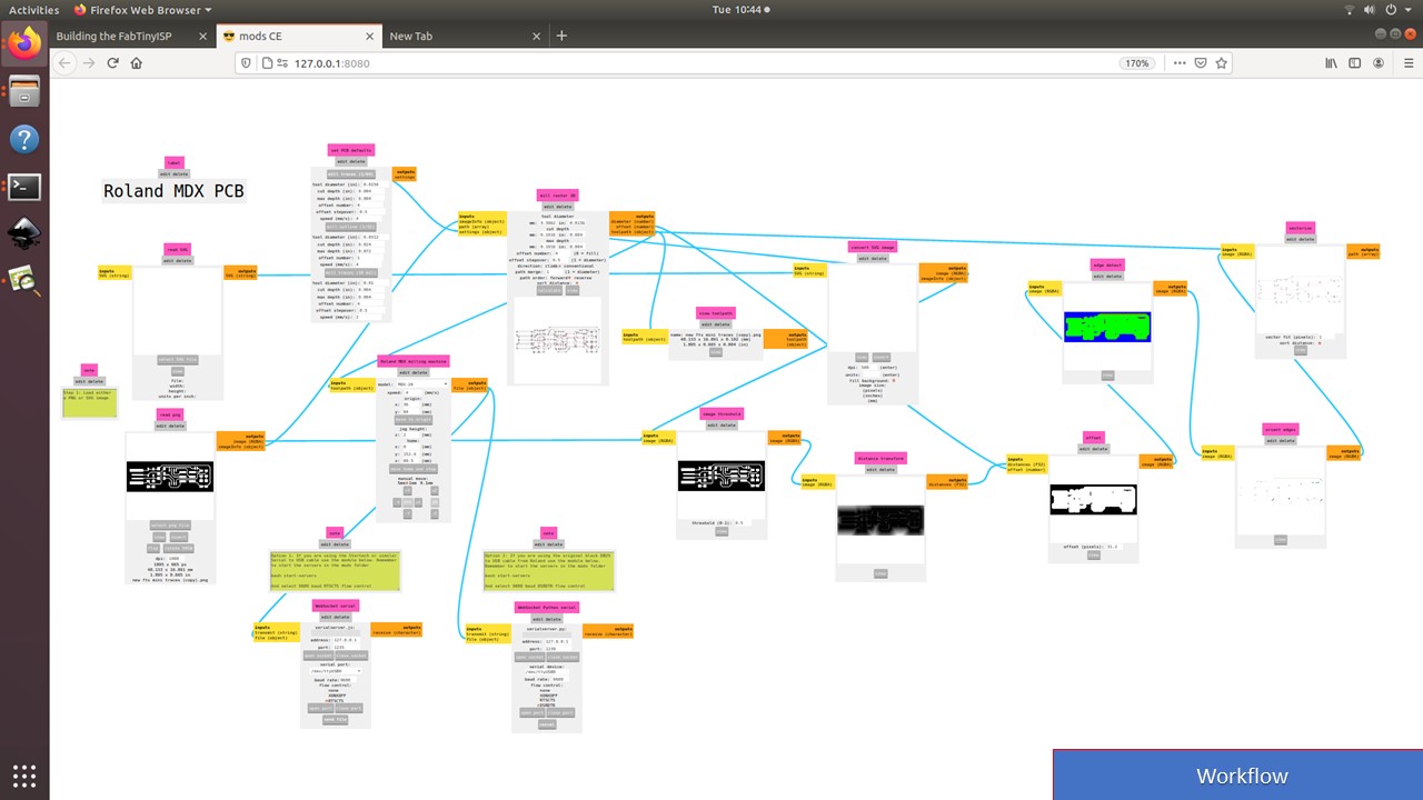
Like the vinyl cutter you have to conduct the following steps to setup MIT Mods.
- First you need to go to Mods folder and must open terminal there by using right click
- Then you need to type bash start-servers which would open MIT Mod interface
- Now you need to select MDX Mill and select PCB to access the Mod workflow
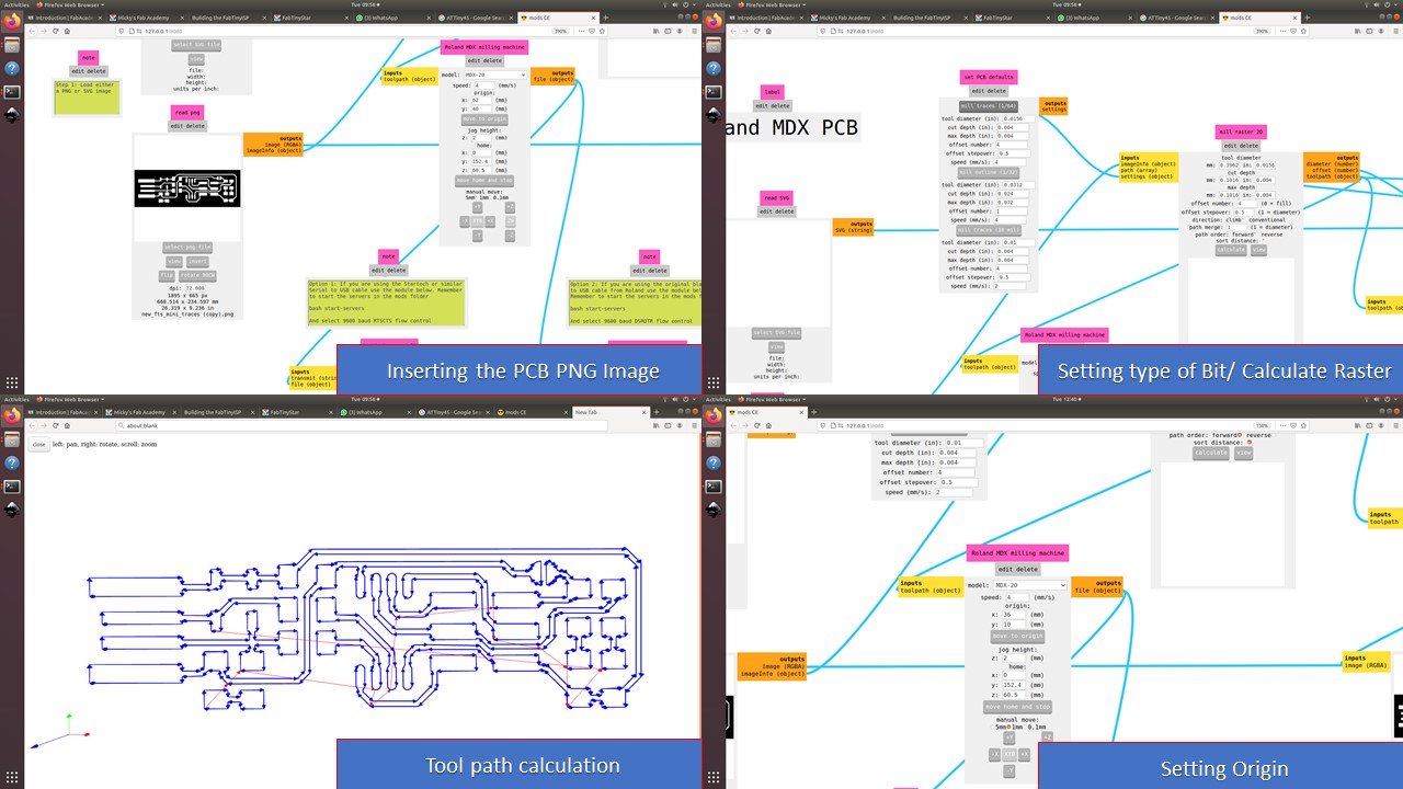
Then you need to export the drawings to the MODS. Always mill out the Traces first using the 1/64 bit and change the tool to 1/32 bit and position the tool to the same origin used for tracing. Afer importing the image you need to calculate the bit and calculate raster. Ensure that you trace first followed by cutting. Once calculation is complete you can verify the tool path by selecting the view command. Next you need to set the origin by going onto suitable coordinates referred from the work area in the milling machine and don't ever forget to remember/screenshot the X & Y coordinates. You can repeat the same process for cutting as well but make sure that you use 1/32 bit and ensure that the origin coordinates are alike.
For 1/64 Tracing bit, I had used the following values
| Feedrate | 4mm/s |
| Plunge Rate | 6 in/min |
| Depth of Cuts | 0.004 in |
For 1/32 Cutting bit, I had used the following values
| Feedrate | 4mm/s |
| Plunge Rate | 10 in/min |
| Depth of Cuts | 0.072 in |
The final step is to verify the origin and to send the file for milling by clicking on send from WebSocket Module.
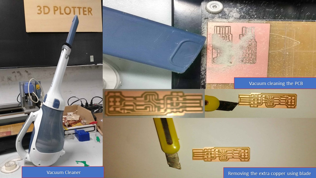
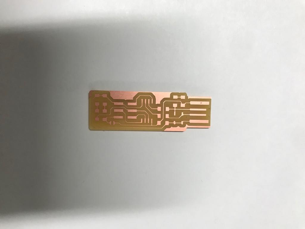
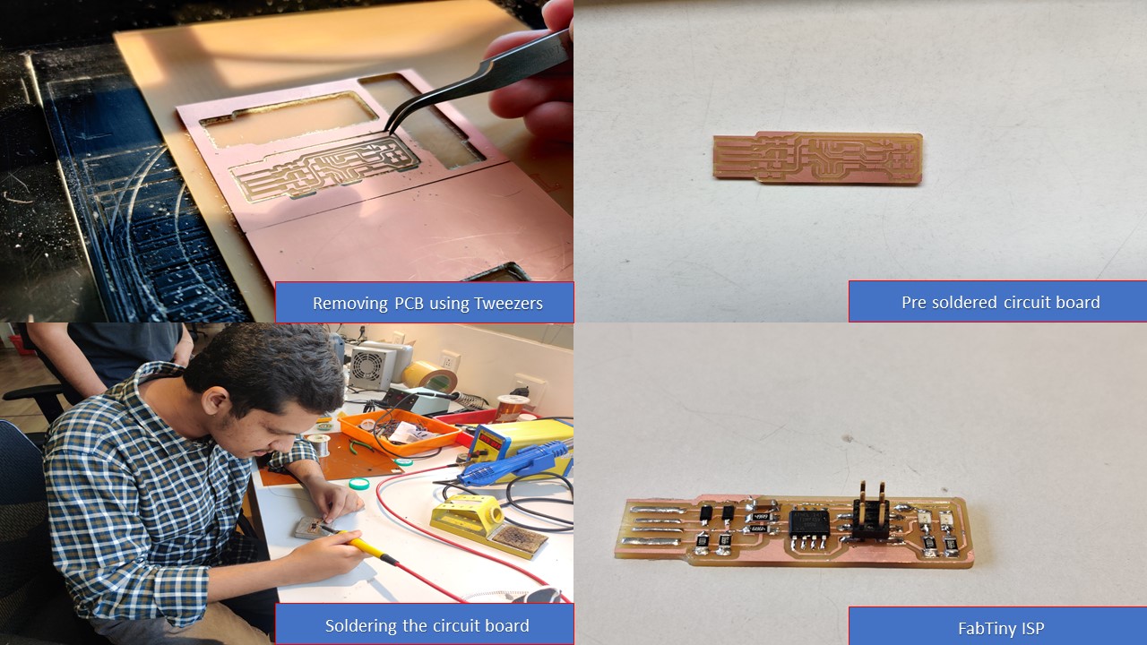
The next step is to clean the board using a vacuum cleaner after completing the whole milling process. Furthermpre, there will be some unwanted copper in the PCB which can be easily removed using a knife. These steps are depicted below
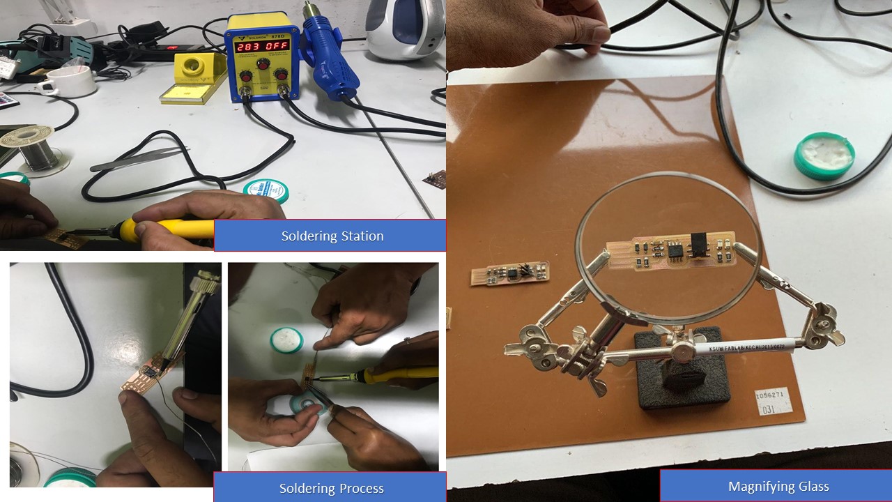
Soldering the PCB
To be frank, I have very little experience in soldering components that too not surface soldering. At first I was scared to solder due to the fear that my hands won't be precise enough to conduct the process. But with the aid of tips about soldering from my instructor and my friend Saheen, I was able to solder the components like a champ. I enjoyed a lot during the process and the following steps depict my journey:
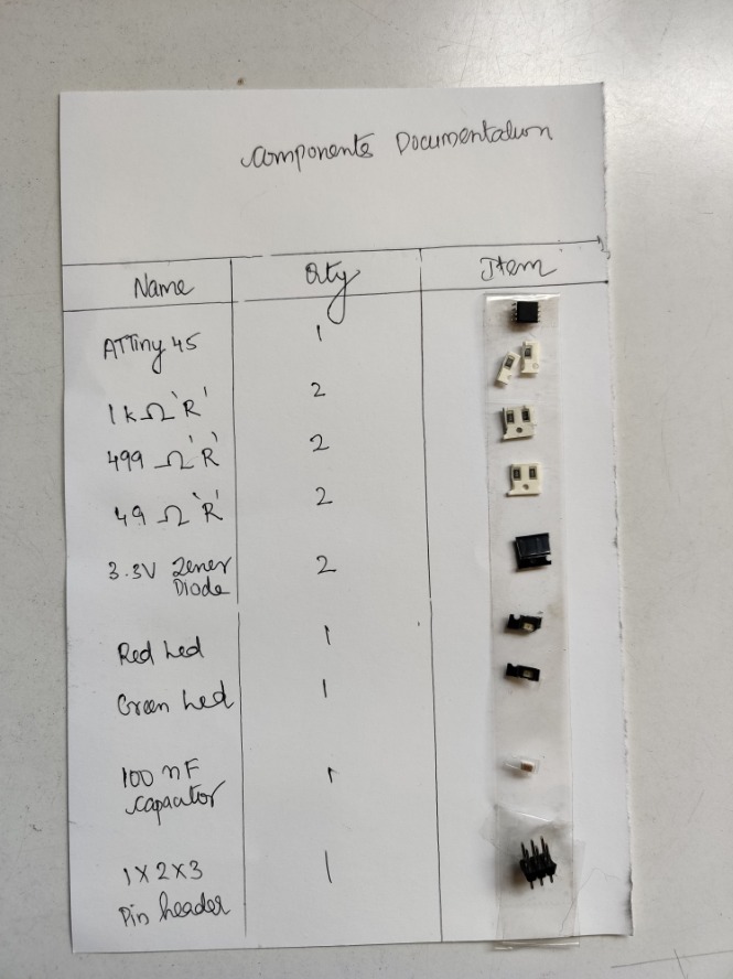
The very first step is to collect all the required electronic components and should stick it against a list of components written in a sheet of paper. I had used a single sided tape to stick components with a little bent at each ends to stick it with the paper. The tape will keep the components in place and it will reduce a lot of confusions in future.
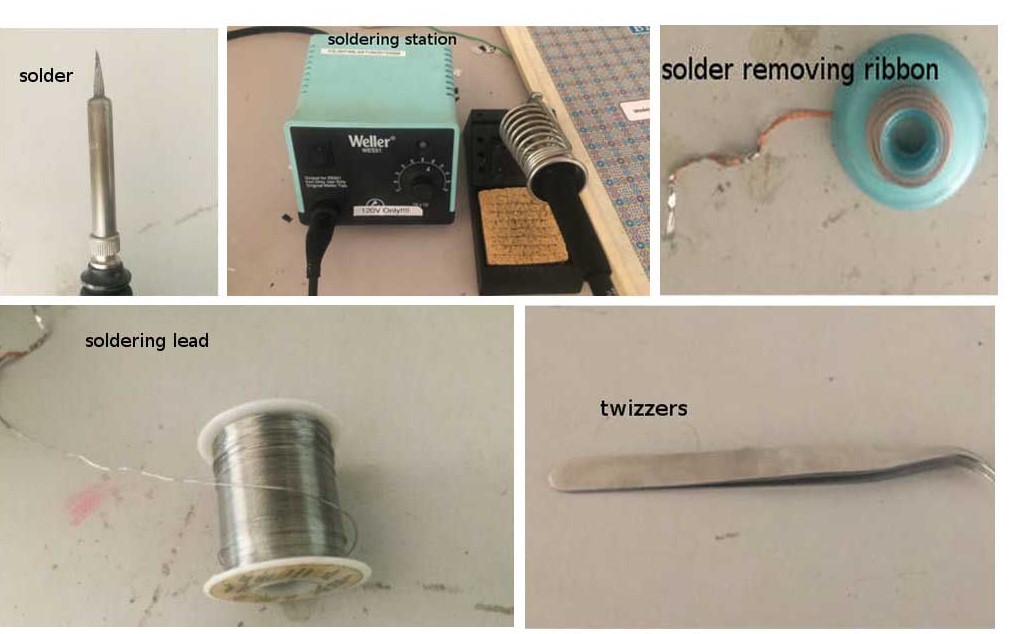
Next I had to assemble all the required components to make the soldering happen. It included soldering station, flux, magnifying glass, twizzers etc.
MISTAKES MADE
- Swapped 1/64 bit with 1/32 bit thereby doing the opposite operation and fortunately due to the blunt tip of the bit the copper plate was not destroyed
- I forgot the origin after the tracing process, so during the cutting process the machine literally destroye the PCB and I had to do the process once again from start
- I was about to mess up with the polarities of the components and due to the help from my friend I didn't mess it up
- My hands were shivering during soldering but my instructor informed me about different ways to increase my precision so it went well
- I messed up with the Z axis distance during the removal of the bit so it was very difficultt to remove the bit without breaking it
- I found that the "cancel" button in the MIT Mods doesn't work so only way to stop the machine is to force stop it using the control button
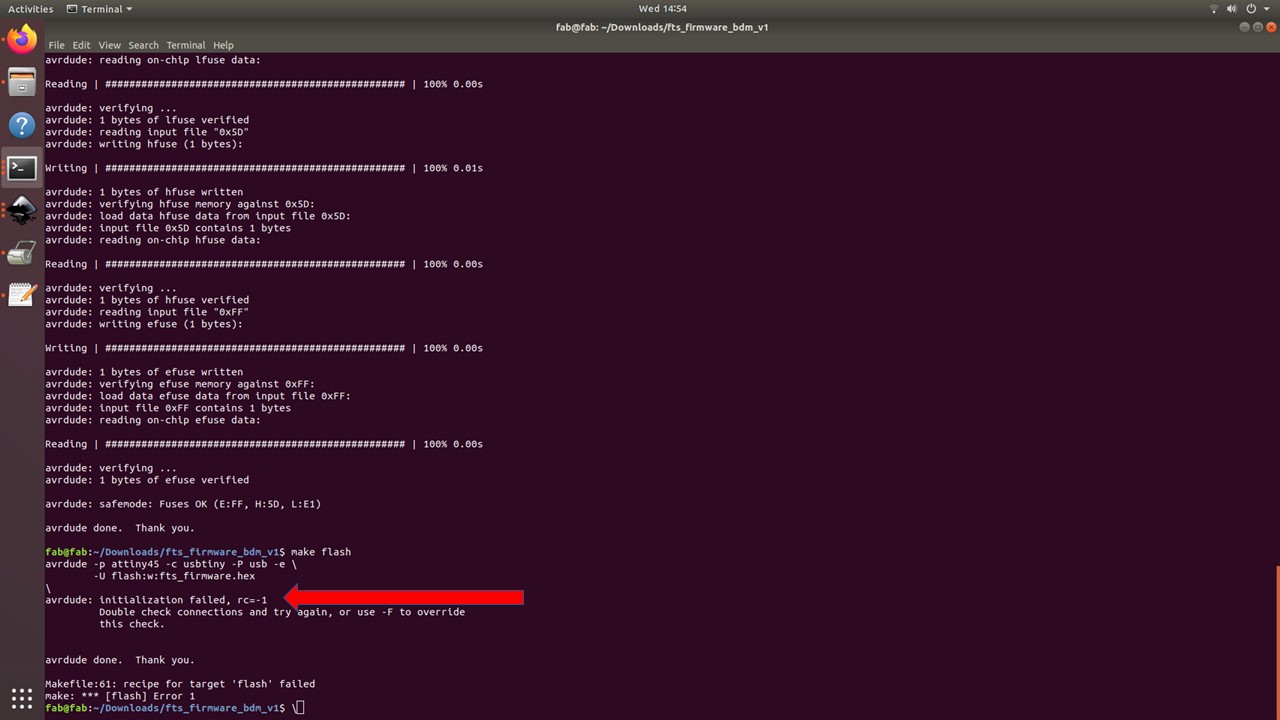
- After soldering I found that I forgot to solder a joint which caused the flash to fail during the first attempt
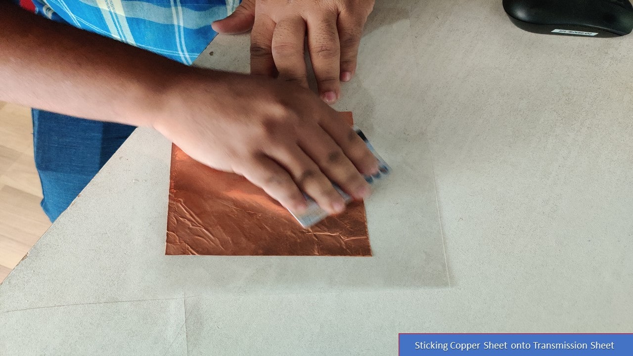
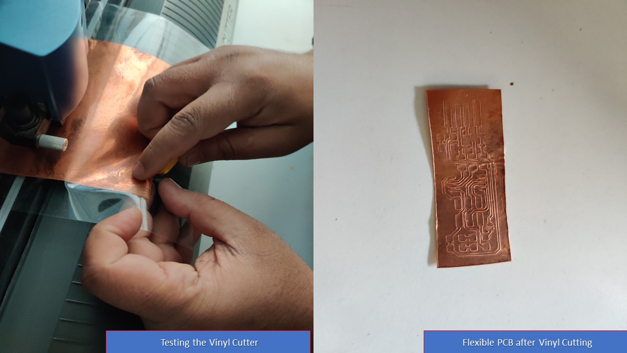
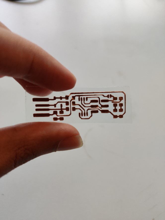
Flexible PCB Using Vinyl Cutter
For fun, I had tried to make a flexible vertion of FabTiny ISP. For that I had used a copper sheet roll, cut out the required dimentions and stuck it onto transmission sheet. Next, I had made the sheet uniformly stick to the surface by using a credit card. Then a test was performed to find the force and velocity and it was 130gf and 2cm/s. Repeating the same procedure using Mods and Inkscape, I had imported the same PNG image and send the file to the Vinyl Cutter. After the cutting, the result was as expected. I had to remove the excess copper from the transmission sheet using a tweezer and a blade. I couldn't solder the componenets since the sheet would melt if I did so.
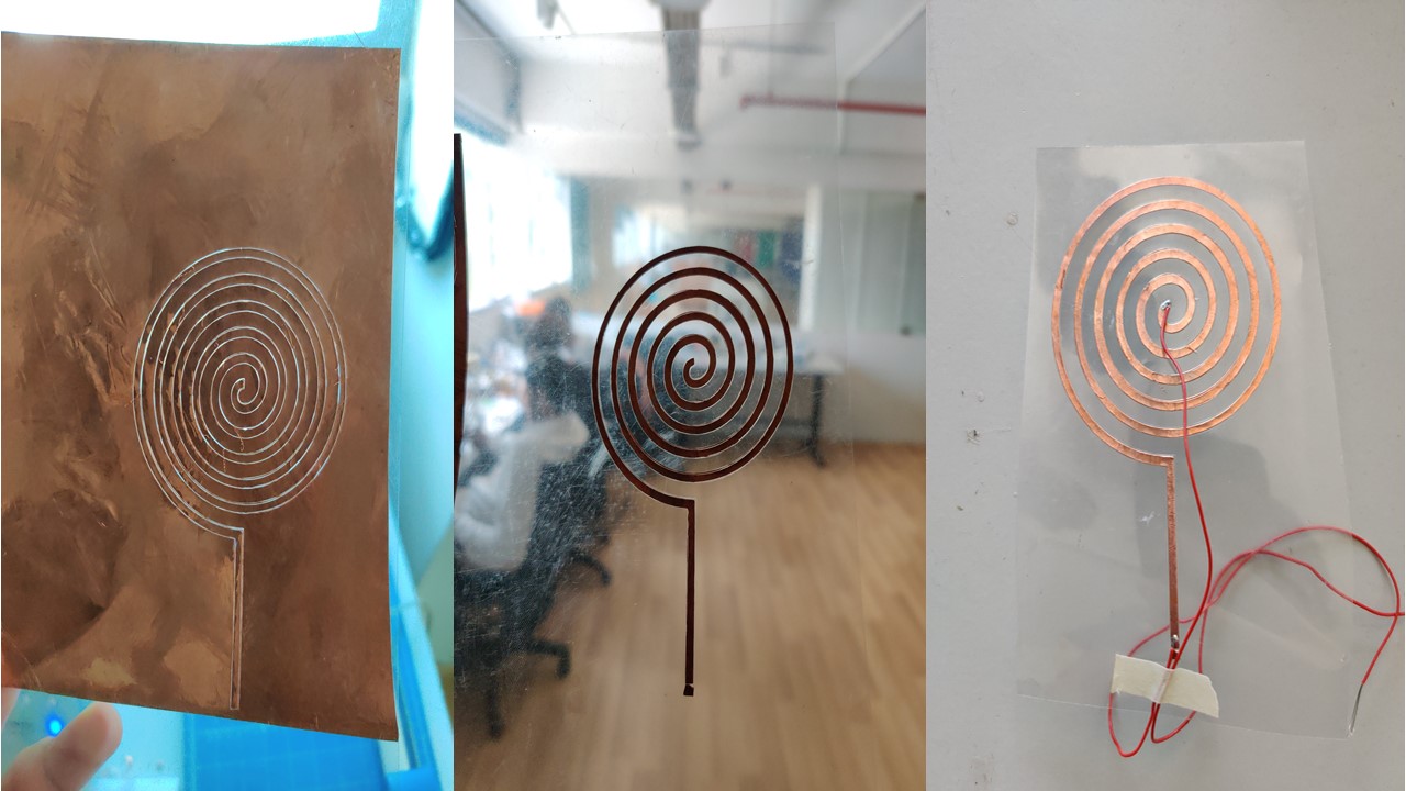
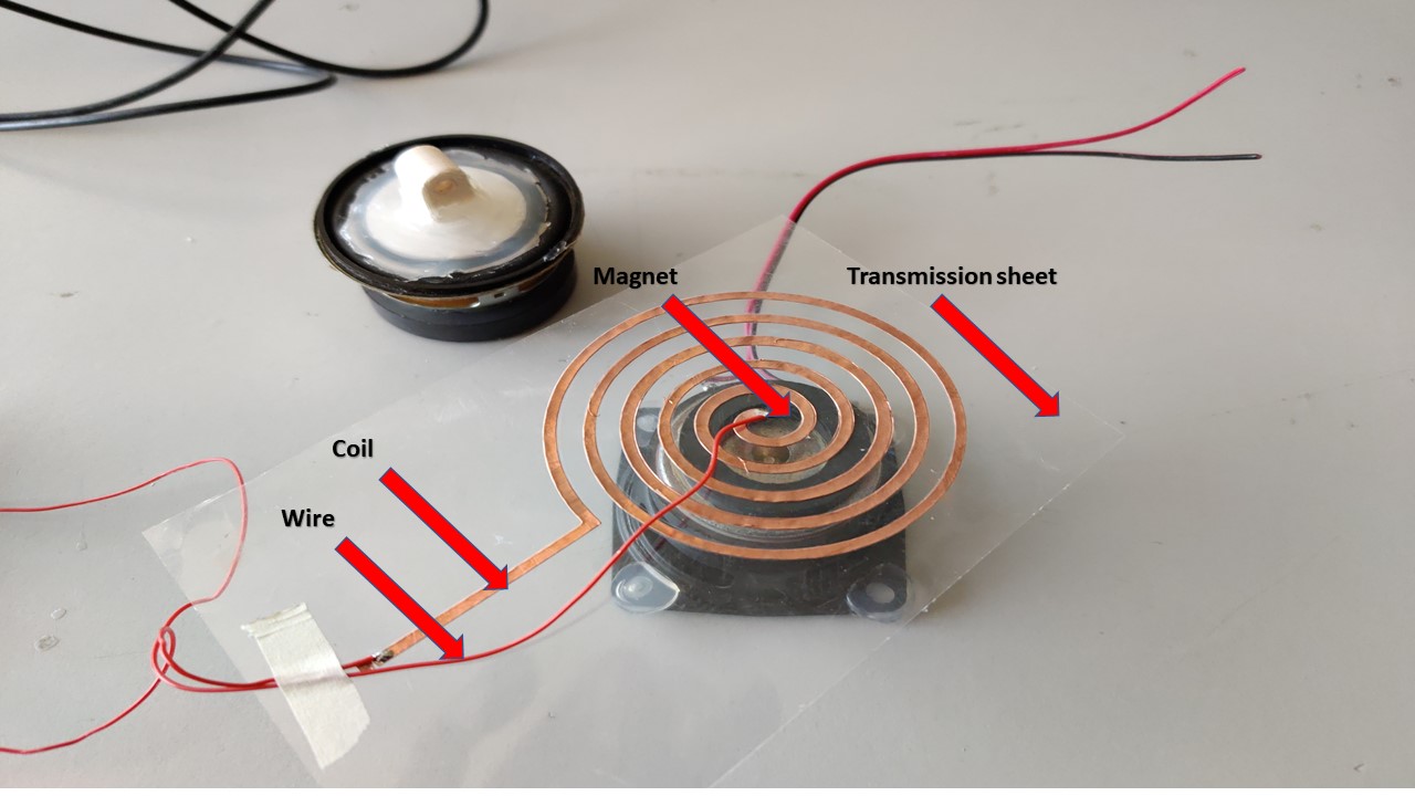
Making a speaker using Vinyl Cutter
The work was inspired from Joao Wilbert's experiment to make speakers using Vinyl Cutting process. Most coil based speakers work through the same principle of using a electromagnetic coil that is connected to a voltage source with the audio signal and a static magnet. Based on this principle I wanted to vinyl cut copper to create a sheet speaker. I selected one of traces from his model with average number of turns, then I had imported that image into MIT Mods. Since I did flexible PCB before it already knew the force and the speed. After that with the help of my friend, I had soldered a wire onto the coil and for testing we had connected the coil to a CRO with a magnet unde the sheet to test the speaker. Hurray, it was working as expected, but the sound coming from the speaker was too low, then we found out the reason that the number of turns was too less. Inorder to test a custom music, I tried to connect the coil onto a audio jack. The steps are explained as follows:
Group Assignment
For the group assignment we need characterize the specifications of our PCB production process.Since i exaplined about the production process during my assignment next one is to find-out the resolution of mill bits we are using.

Initially we milled our test pad with 1/64 bit and chose to mill one board with offset as 4.
Next we tried the 1/32 bit.
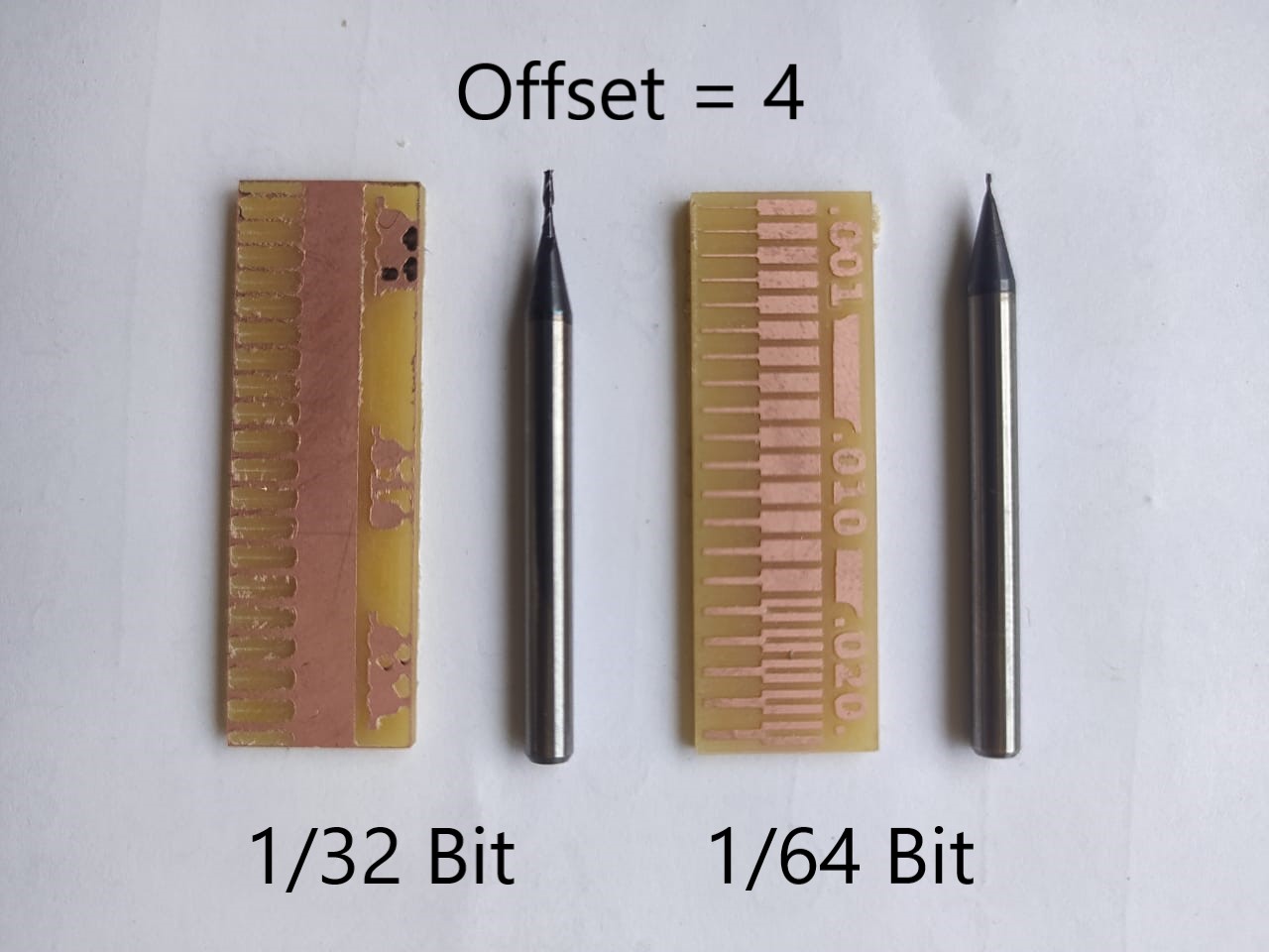
This image clearly shows the difference in milling resolution of 1/32 and 1/64 bits. Usually we use the 1/64 bit for milling trace and 1/32 for cutting and drilling. So it is okay of drilling and cutting.
Programming the PCB
Plug the board into a USB port. USB2.0 is preferred over 3.0 if you have one, and use an extension cable so that you do not put strain on your board especially if your port is upside down. If you installed the red LED, it should be lit up now. If not, check the solder jumper and make sure that it is bridged. If your computer complains about a USB device drawing too much power, unplug the board and check for shorts. Connect the programmer to the ISP header on your board. Note that there are two different orientations in which you can connect the cable; it is imporatant that you get pin 1 in the right place. Pin 1 is the MISO pin and it should be connected to the MISO pin of the board you are programming. Once you finish soldering the components, It is time to test the connections and program the board. Look carefully at the board to see if all the connections are proper. For Programming I referred the link First we need to install all necessary software for programming, which include "Avrdude" and "GCC" To install these softwares in Ubuntu, Open the terminal and follow the steps :
- sudo apt-get install flex byacc bison gcc libusb-dev avrdude
- sudo apt-get install gcc-avr
- sudo apt-get install avr-libc
- sudo apt-get install libc6-dev
Now we need to download and unzip the firmware To download and unzip the FABISP firmware, Open the terminal and follow the steps :
- cd ~/Desktop
- wget http://fab.cba.mit.edu/classes/863.16/doc/tutorials/fabisp_programming/fabISP_0.8.2_firmware.zip
- unzip fabISP_0.8.2_firmware.zip
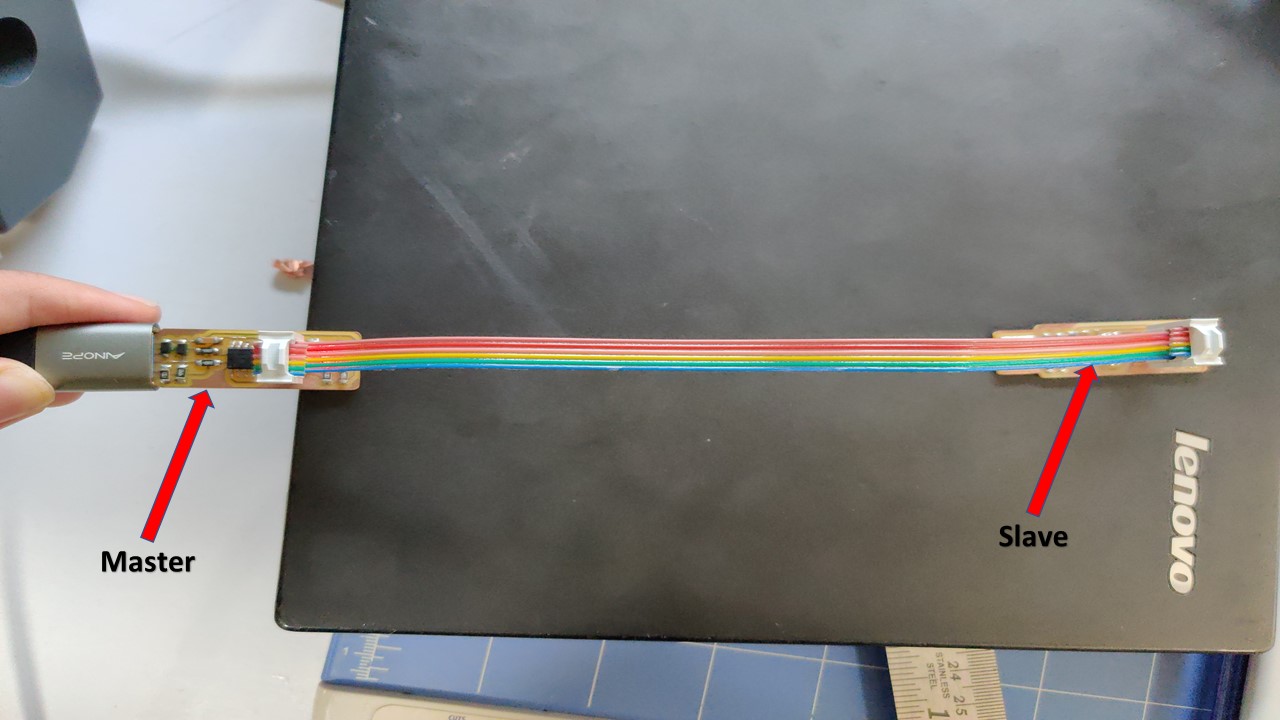
My programmer cannot communicate with the computer directly, so I connected it to an already porgrammed programmer which can communicate with the computer and translates the messages to my programmer.
The "Makefile" in the downloaded firmware is set up to work with AVRISP2 by default, Since we are using Atiny45 this firmware wont work. So you can use this file
Programming the FabTiny ISP
Follow the steps to run the device:
- Go to the unziped firmware folder and open the terminal.
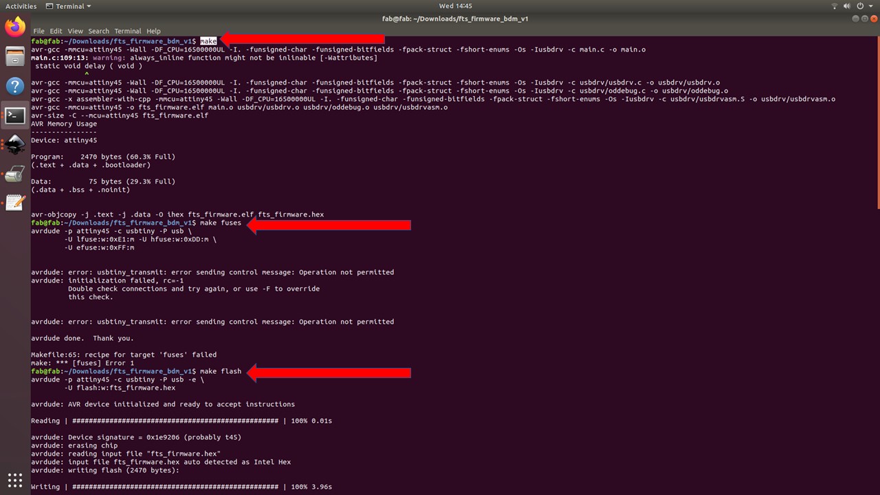
- type "make"
- type "make flash"
- type "make fuses"
- "make rstdisbl"
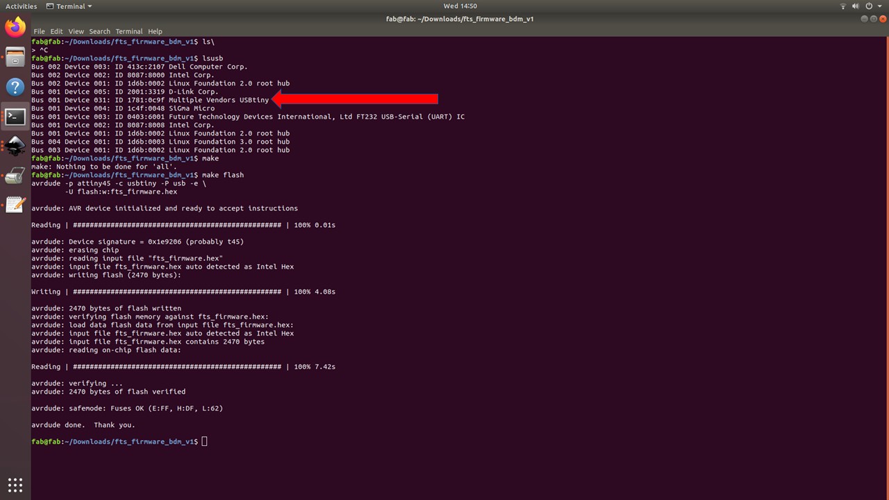
I had used lsusb command to recognize the ISP programmer and my PC had identified it successfully.
Blow the Reset Fuse
We need to change the bit that will turn the ATtiny45's reset pin into a GPIO pin.This will disable our ability to reprogram this ATtiny45 in the future, hence make sure everything is working before doing this. Connect your ISP programmer to your board one more time, and in the Terminal run. For that you need to type:
- make rstdisbl.
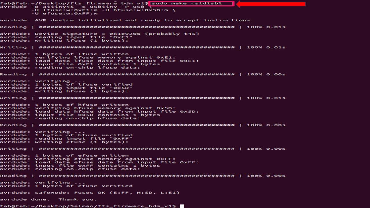
This does the same thing as the make fuses command.with that, avrdude will never be able to talk to this chip again through the ISP header. Now our programmer is finished. To check the disabled pin. We can use the following command.
- make flash
Hurray, the programming was successful!