WEEK 6: ELECTRONIC DEVICES
INDIVIDUAL ASSIGNMENT:
REDRAW THE ECHO HELLO WORLD BOARD. ADD ATLEAST ONE BUTTON AND A LED(WITH CURRENT-LIMITING RESISTOR) OR EQUIVALENT INPUT AND OUTPUT, CHECK THE DESIGN RULES, MAKE IT AND TEST IT.
REDAW THE ECHO HELLO-WORLD BOARD.
There are several steps to redrawing the Echo hello-world board, which I list below:
1. Download and install any PCB designing software and get familiar with it
2. Download and install FAB libraries to get the list of components which are available in FABLAB
3. Enbrst the components which is seen in given hello-world board.
4. Redraw the echo hello-world board by adding input and output in it i.e, atleast one button and LED with current-limiting resistor
5. Generate .rml files of traces and outer boundary of PCB
6. Mill the PCB by giving .rml file to ROLAND SRM-20 milling machine
7. Sold the components on PCB
8. Test the board by burning program in it.
DOWNLOADING THE EAGLE.
EAGLE is a scriptable Electronic Design Automation (EDA) application with schematic capture, printed circuit board (PCB) layout, auto-router and computer-aided manufacturing (CAM) features. EAGLE stands for Easily Applicable Graphical Layout Editor (German: Einfach Anzuwendender Grafischer Layout-Editor) and is developed by CadSoft Computer GmbH. The company was acquired by Autodesk Inc. in 2016. This software is very easy for the biggners so I am using it for desiggning the schematic and PCB layout for my design. This was all about the Eagle software now you can download the EAGLE from here
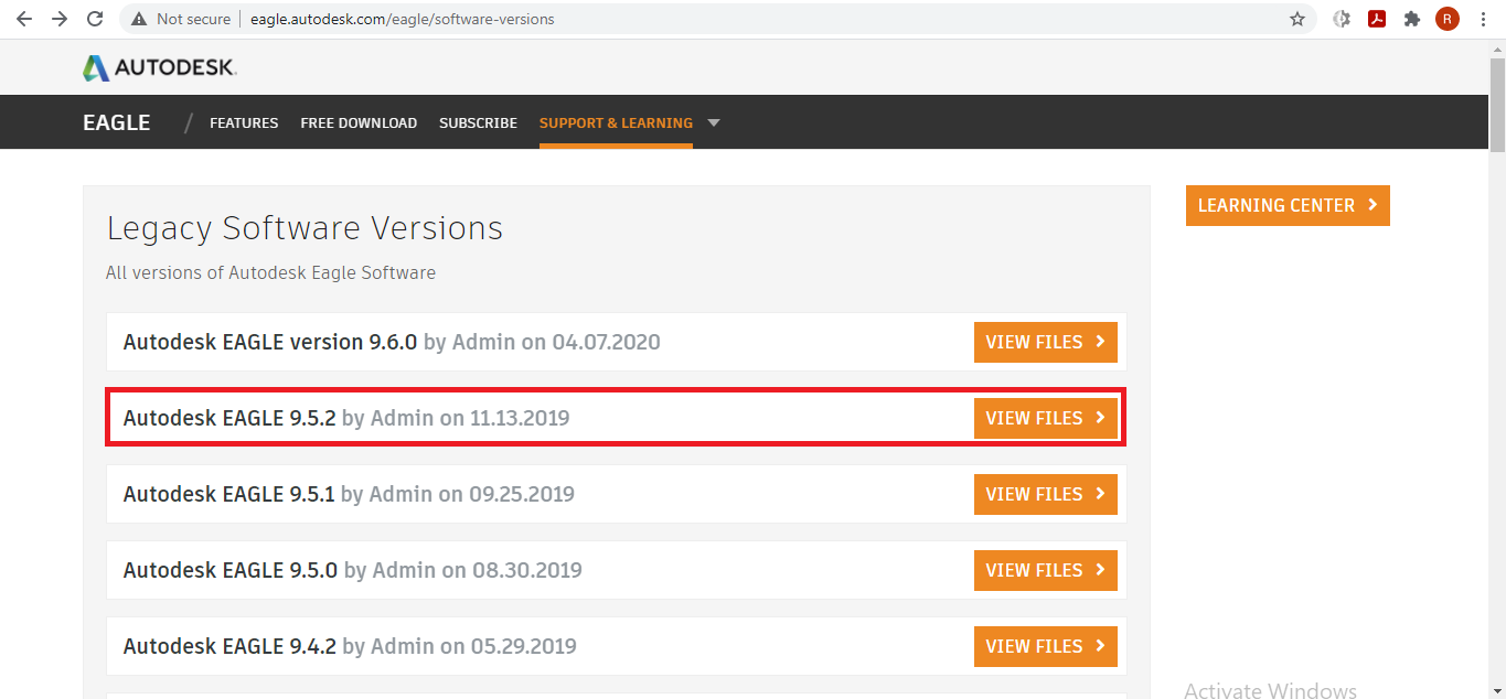
I downloaded the 9.5.2 version of the Eagle.
FAB LIBRARY.
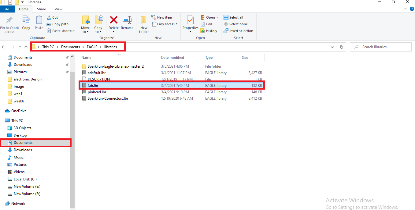
After Installation of the EAGLE software we need the library to add the required components in the schematic diagram. The components are available in the Fab.lbr you can download the Library from here
I also added some other libraries like sparkfun and pinhead library to add more component in my list. you can also check the libraries either included in the eagle or not. open library in schematic then library manager after that in use and browse it you can see here.
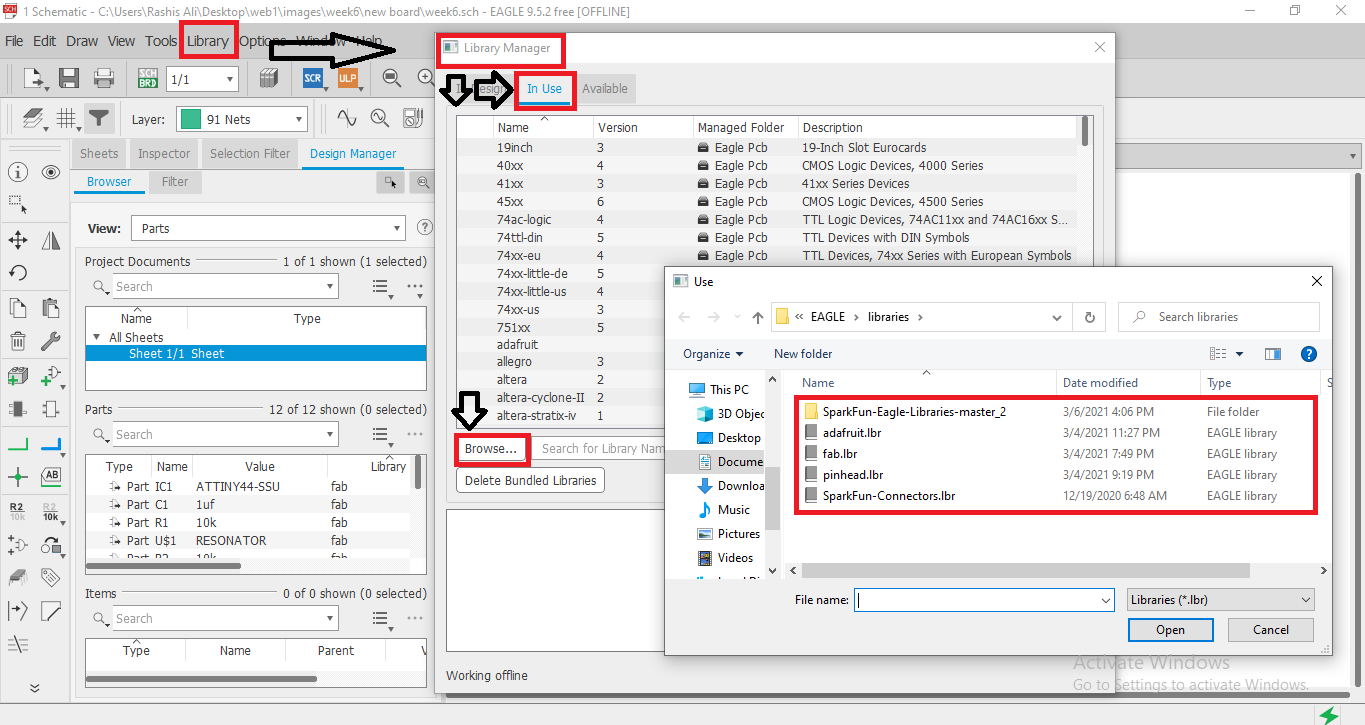
you can see that all the libraries are included in the EAGLE.
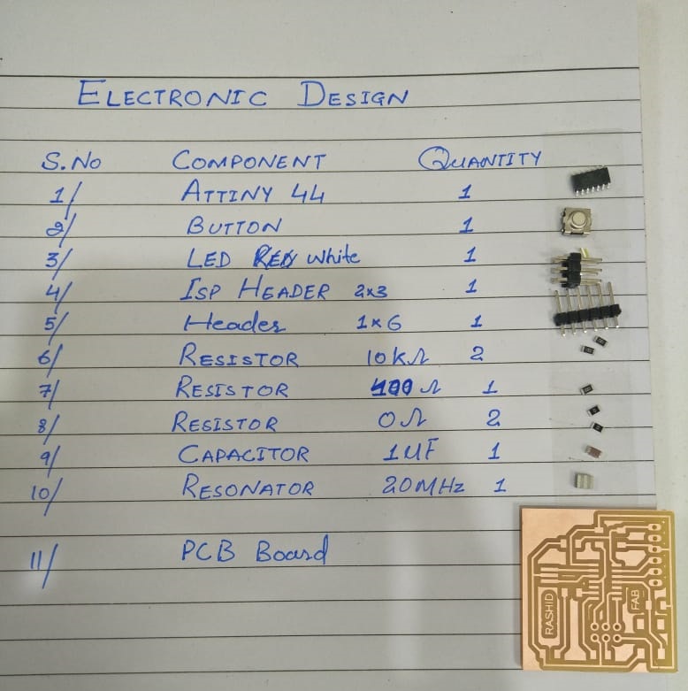
COMPONENT LIST.
We can now use fab library layouts to build the PCBs. Before starting to design, it's a good idea to make a list of the components we'll need in the PCB. Our task is simple; the circuit has already been built we all need to do now is to add an LED and a button. The LED requires a current limiting circuit, and the button requires a pull-up circuit; all of these components need a resistor to restrict the current. I used 10k ohm resistor for button and a 100 ohm resistor for led.
Component list which I will use for my schematic.
1. ATTINY 44.
2. BUTTON.
3. WHITE LED.
4. ISP HEADER 2*3.
5. MALE HEADER 1*6.
6. RESISTOR 10K ohm.
7. RESISTOR 100 ohm.
8. RESISTOR O ohm.
9. CAPACITOR 1Uf.
10. RESONATOR 20MHZ.
11. PCB BOARD.
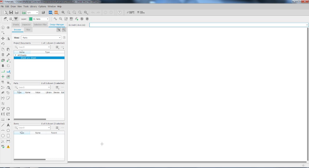
When you select Project, a "Empty Project" is created in the Eagle folder. Right-click to open the schematic and rename it.
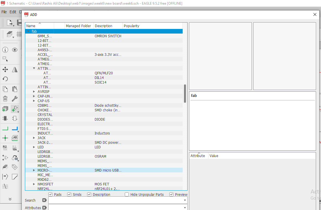
To design a circuit schematic, click on "Add tool" in the left toolbar, which opens a window where we can pick components from the Fab library.
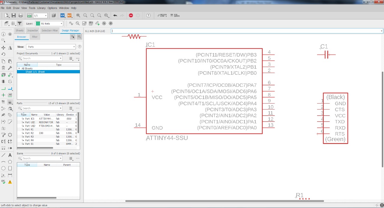
After that selecting the components and placing them to schematic.
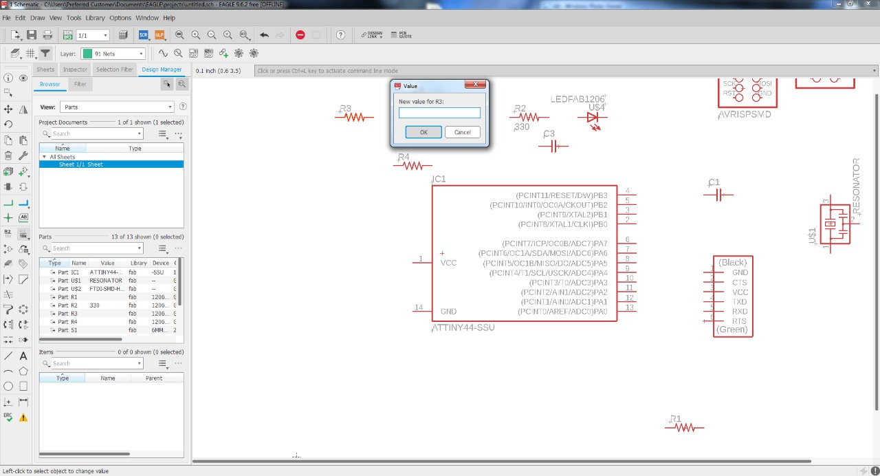
right click on component "Resistor/Capacitor" then select the value and give them desire value.
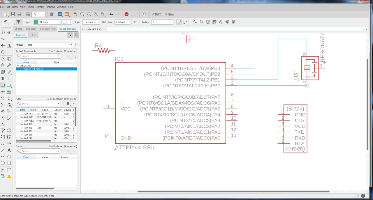
Now select net line tool in schematic to connect the Attiny 44 board to the other components.
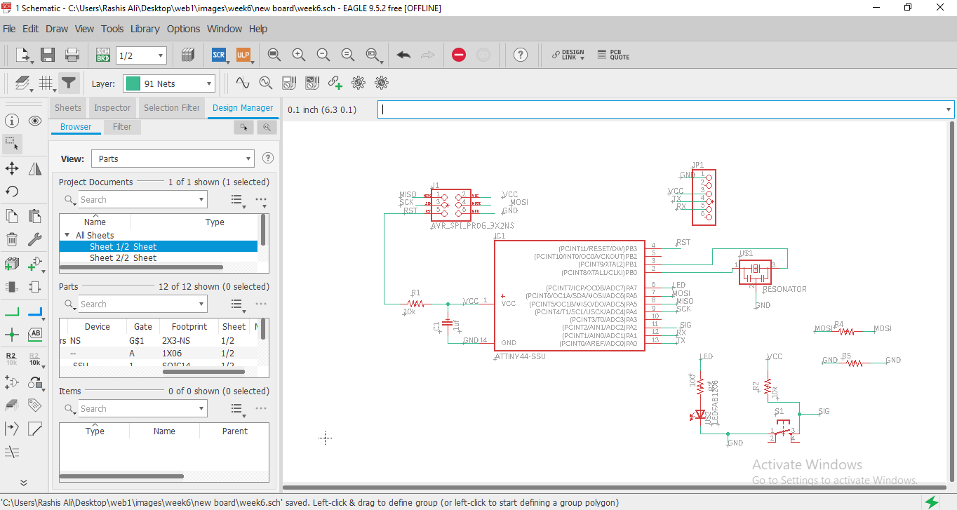
This is the final Schematic Diagram of the PCB board on EAGLE.
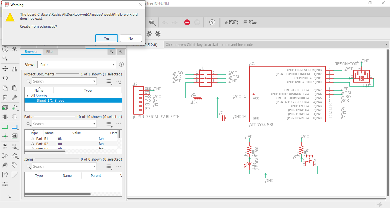
Now we'll switch the schematic to a PCB Board view, where we can draw tracks. click on Generate/switch to Board then it will give permission while selecting on "yes".
SWITCHING TOWARDS THE BOARD LAYOUT.
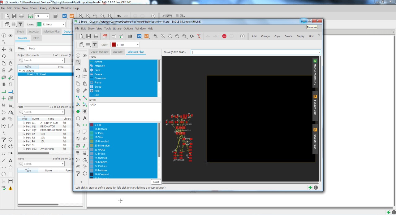
Here in board we make Group and place all the components inside the axis dimension.
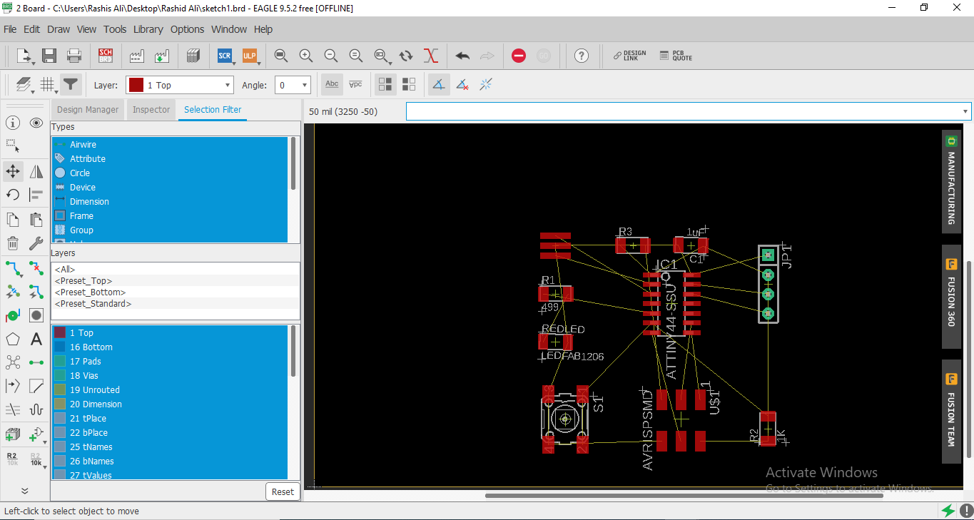
Route the wires in elegent way. Try to avoid any overlap.
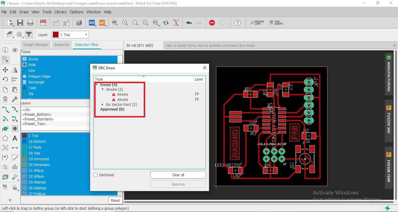
This is the PCB routing. Once the schematic diagram is complete, we must check the ERC (Electrical Rule Check), which we can do with ERC command. I had four errors, All of the alerts were caused by Airwire and no vector font was due to "Text" in the circuit . This phase is shown in the image below.
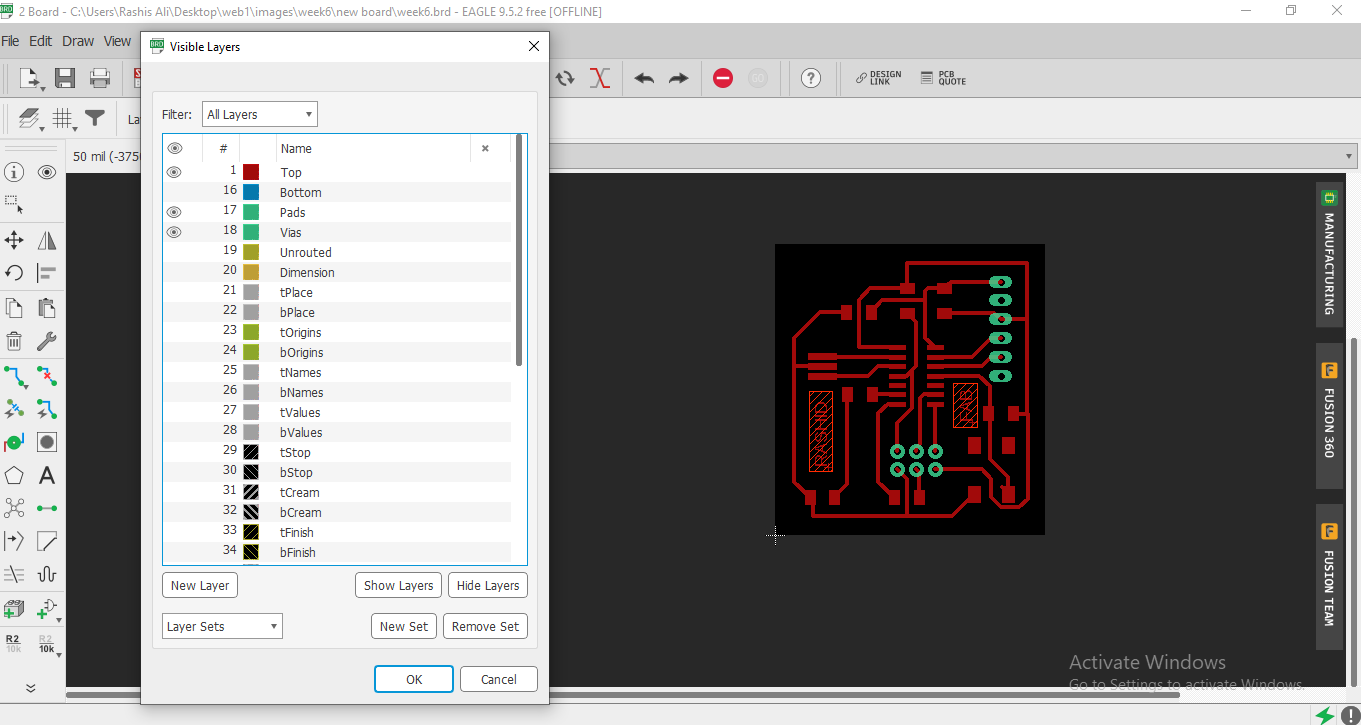
Click on layers setting and show above layers for generating PNG image.
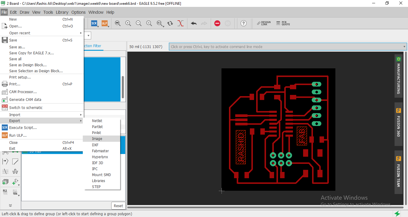
Click on file then Export and select image.
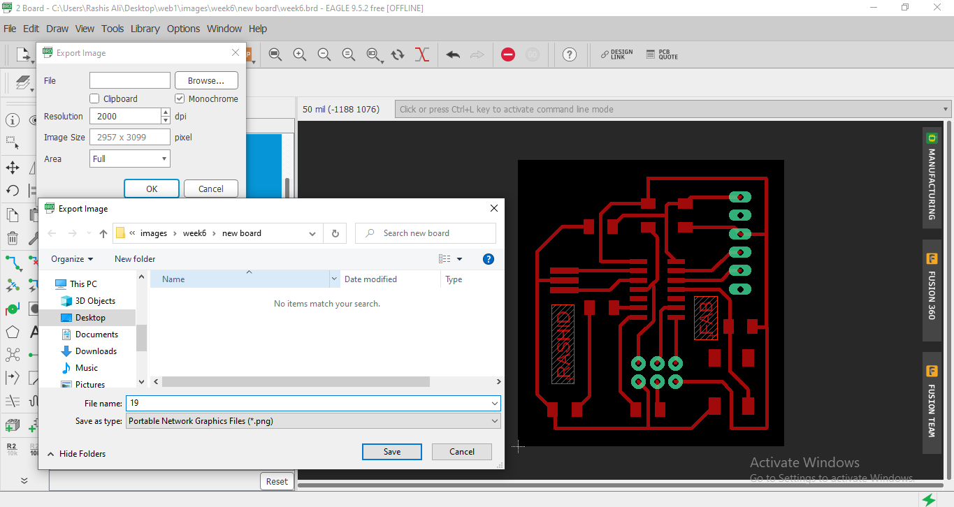
Now set the resolution and select on monochrome for Black PNG Image then select the desired folder and name the image.
GENERATION RML FILE FOR ROLAND SRM-20.
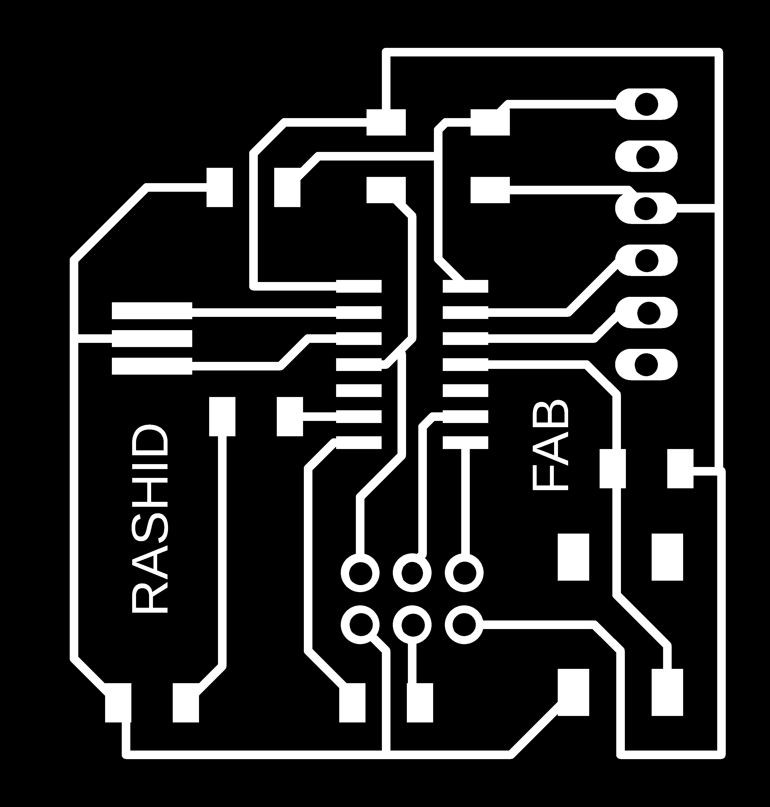
exporting Image with monochrome.
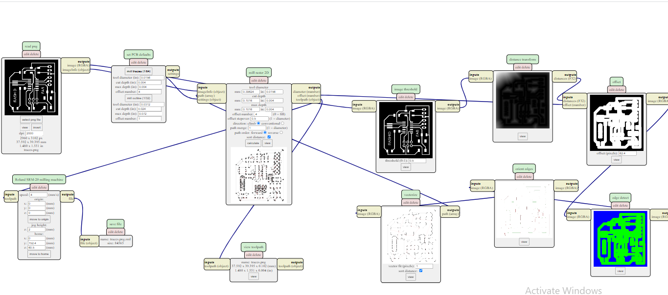
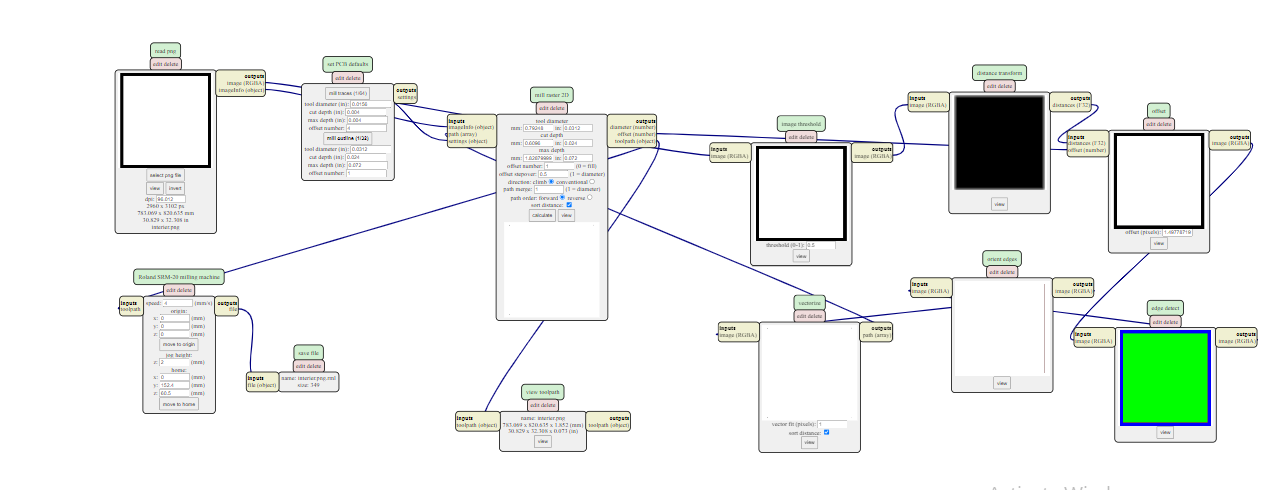
Generating RML file for Traces in "mods.cba.mit.edu." to generate .RML files (detailed method is described in week-5)for further process in Roland SRM-20 Milling machine.
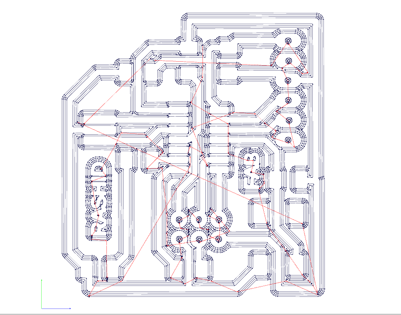
This is RML file for Traces

Now from the PNG Image I have to generate the outline and drill by Images in paint.
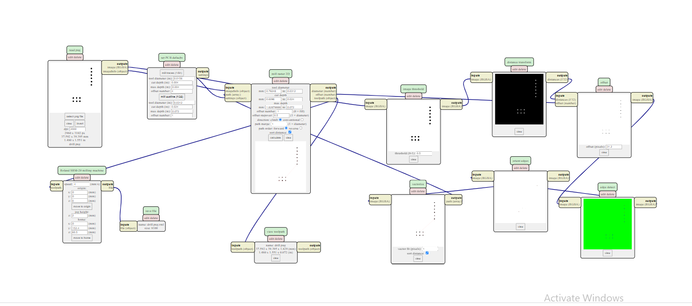
Generating RML file for Drill/Holes by mods
Generating RML file for Interier/Border by mods
MILLING PROCESS.
.rml files are given to Roland SRM-20 Milling Machine. For traces 1/64 drill bit and for outline we are using 1/32 drill bit
BILL OF MATERIAL.
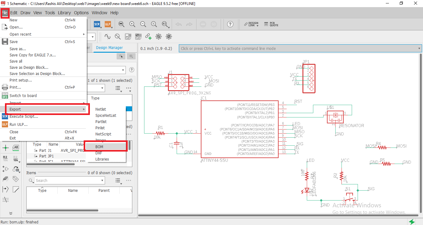
Now genetrate the bill of material in the Eagle open schematic, click on file export and then BOM .
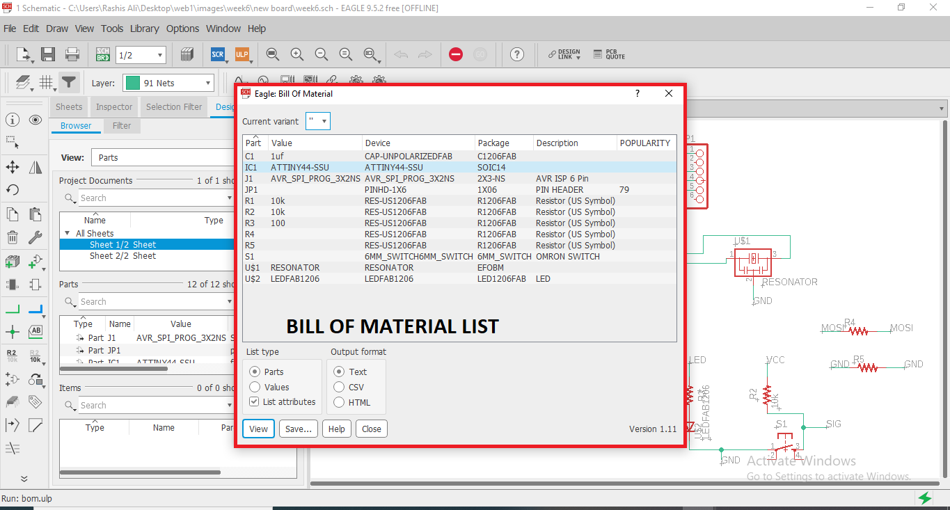
After clicking on BOM This list of material/component appears.
I listed the component and placed every SMDcomponent in the list that will be easy.
SOLDERING.
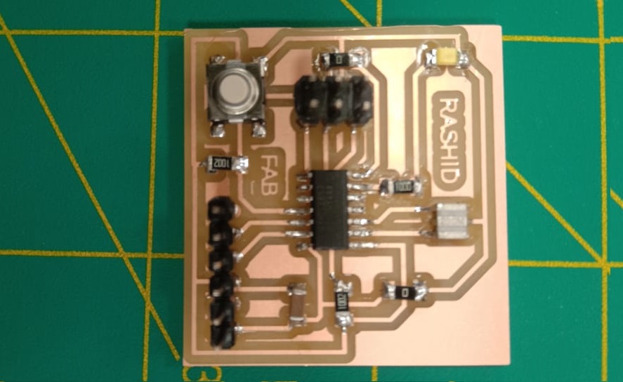
After soldering the components in the PCB board. Now board is ready for Programming.
BURNBOOT LOADING.
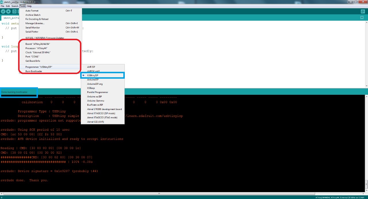
After Soldering we burn bootload the board to make it programmable. open to ardiuno software then the Board Manager and select the Board attiny44/85/25 after set the Prcossor Attiny-44 and in last Select the 20MHz clock processor.
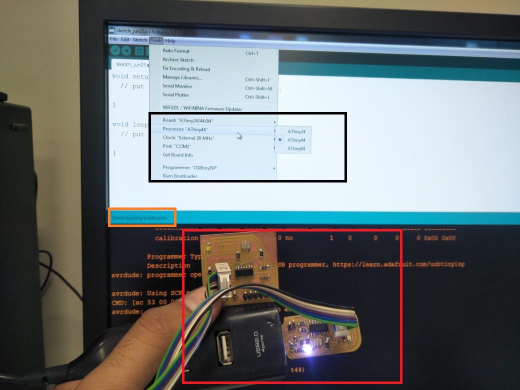
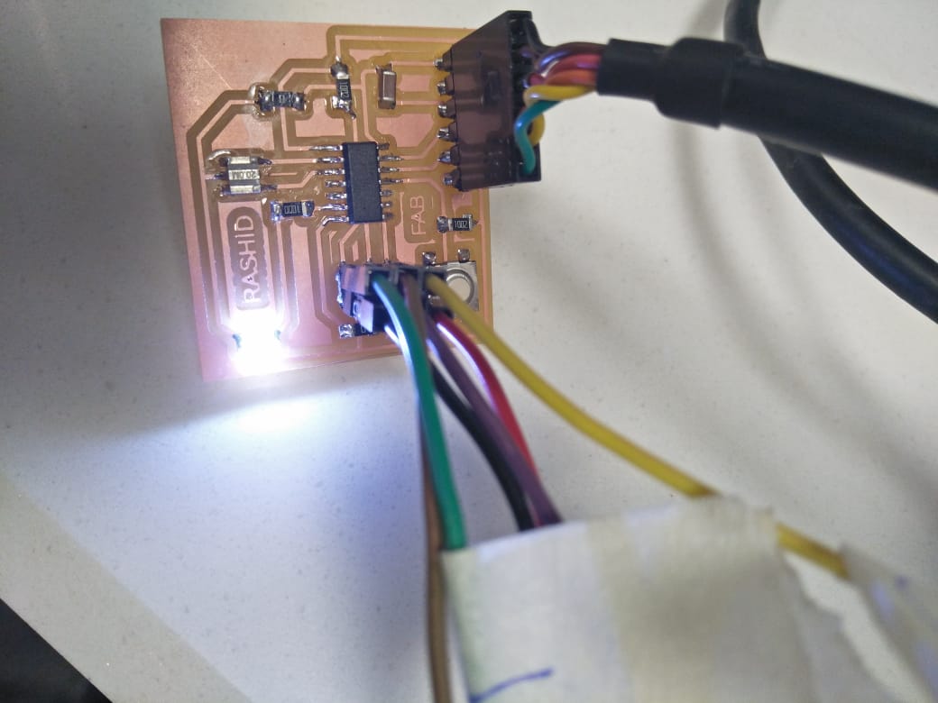
I used fabIsb cable and ISB board for burnboot loading in my Attiny44 board. you can see in the above picture.
PROGRAMMING AND TESTING THE PCB BOARD.
After finishing the soldering, we'll burn the code in the echo hello-world board using our week 5 development board and FTDI cable. To upload code, I'm using the Arduino IDE. first, we burn the code, then we upload the blink code to the hello-world board.
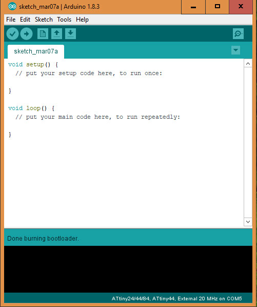
Done burning bootloader in the Arduino IDE.
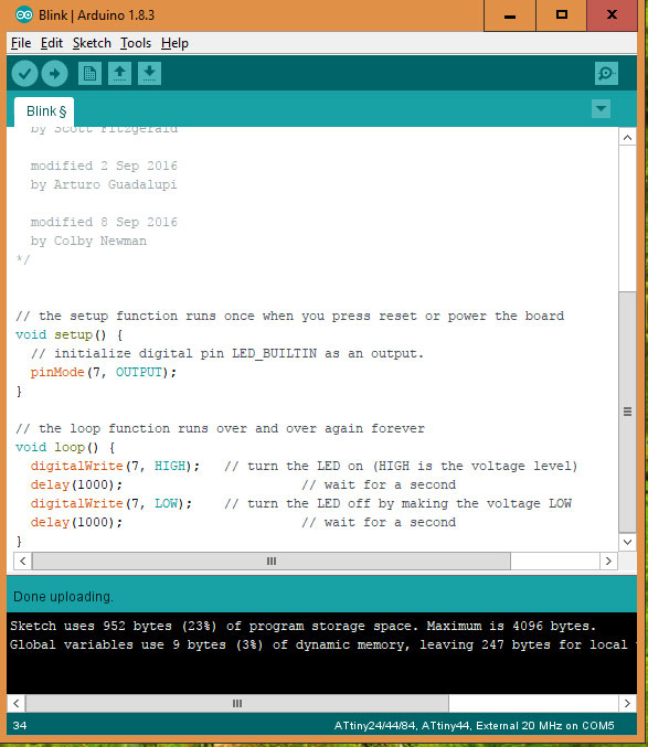
Done Blinking Program in Attiny 44 using Arduino IDE .
The code is working and the LED is Blinking after every 1s of delay.
GROUP ASSIGNMENT:
USE THE TEST EQUIPMENT IN YOUR LAB TO OBSERVE THE OPERATION OF MICROCONTROLLER CIRCUIT BOARD
Digital Multimeter is a device which used for the Electronics and Electrical equipments measurements. It is most important and useful equipment for testing and Troubleshooting of electronic Circuits. We can check Connectivity, Resistances, inductance and voltage in the circuit using multimeter. We decided to check component in echo-hello world circuit using multimeter to confirm the values of components and to check either they are in working condition or not.If the multimeter beeps, the line is connected; otherwise, there is no connection.
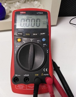
We must first check the meter to see whether it is working or not. So, it's working Properly.
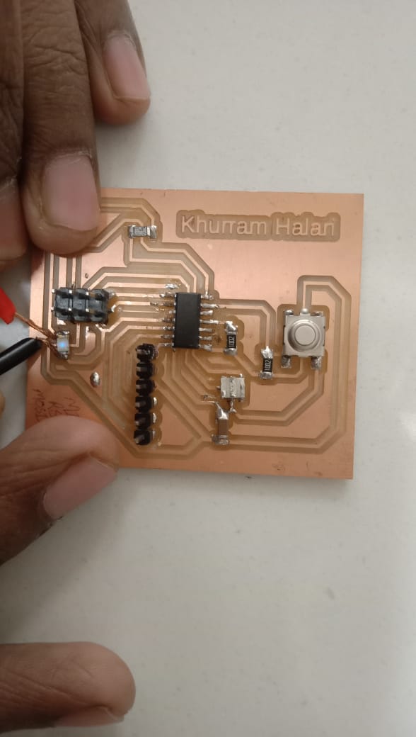
CONNECTIVITY CHECK .
The first phase after milling and soldering is to verify the circuit's connectivity. Our circuit will not function properly if any line is not properly connected to the IC or any part. Rotate the dial on the multimeter to diode and click the beep button to test connectivity. Then add the multimeter's anode and cathode to the line that is supposed to be attached.
Components are properly connected in the Board.
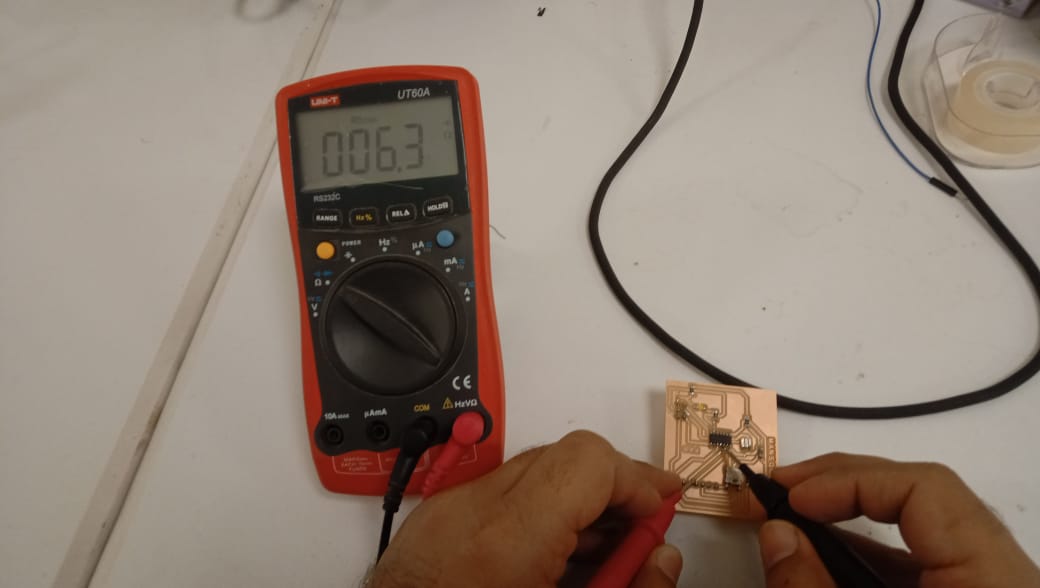
RESISTOR TEST.
Resistors are an essential component of any electronic circuit. The value of the resistor is crucial. If we use a resistor with the wrong value at any point in the circuit, it can cause the circuit to fail or, in some situations, it may affect other components as well. Non-polarized resistors are used.
Place both probes of the multimeter across the resistor and set the dial to resistance. The value will be shown on the multimeter's screen.
CAPACITOR TEST.
Capacitor are an essential component of any electronic circuit. The value of the capacitor is crucial. If we use a capacitorstor with the wrong value at any point in the circuit, it can cause the circuit to fail or, in some situations, it may affect other components as well. Non-polarized capacitors are used.
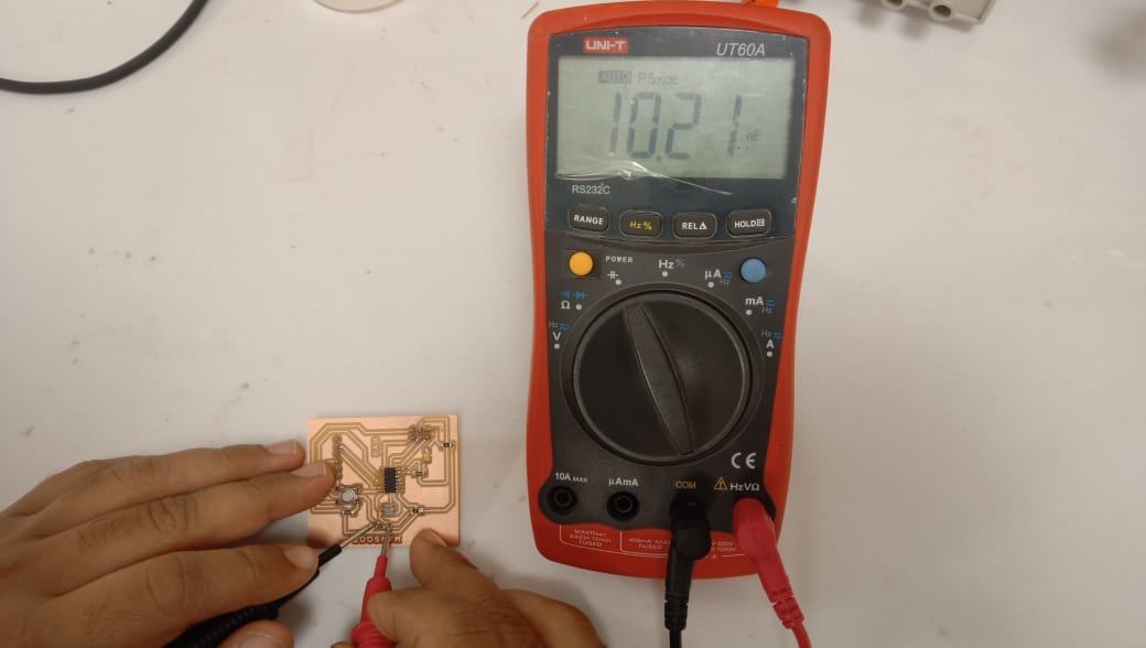
Now check the value of the capacitor in the PCB Board using Multimeter
LED TEST.
Now to ensure that the LEDs are properly soldered and that the polarities of the LEDs are right. To test the LED, set the multimeter's probes to LED. Attach the cathode to ground and the anode to the LED's supply side. If the LEDs glow, they are in the correct position.
If the LEDs do not lights up, check the soldering or the polarity.
Propeller Led Pendulum Clock by Engr. Rashid Ali is licensed under Attribution-ShareAlike 4.0 International![]()
![]()
![]()