WEEK 15: WILD CARD
DESIGN AND FABRICATE A 3D MOLD AND PRODUCE A FIBER COMPOSITE PART IN IT WITH RESIN INFUSION AND COMPACTION:
In this week I want to make fiber composite dustpan. For this I start working in Solidworks to make it's mold. Following are steps to make 3D mold of dustpan.
3D DESIGNING IN SOLID WORKS.
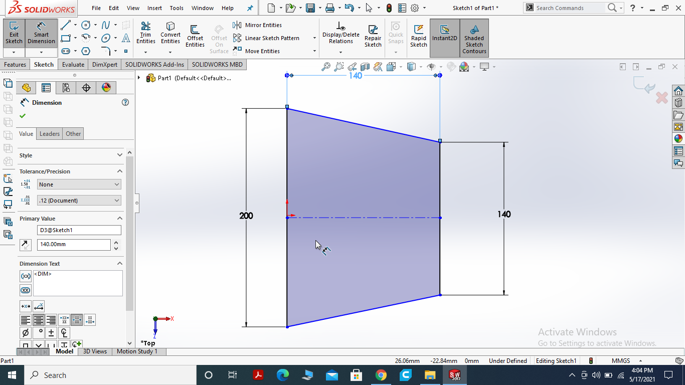
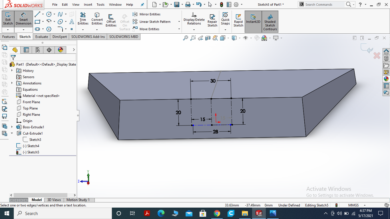
I sarted the design for dustpan I draw the center rectangle and then draw the desire shape while triming the undesire part.
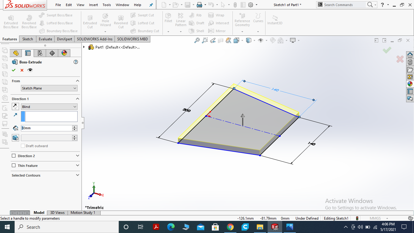
I feature bose the part with 30mm as we know the shape composite foam (thermopole) size is 40mm .
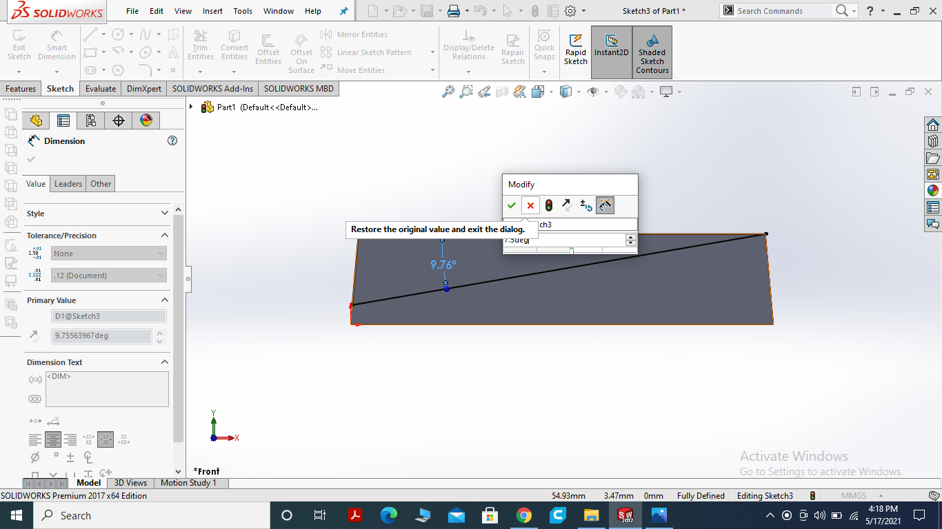
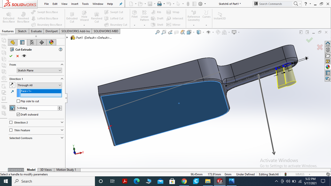
for making slope I draw the line with new sketch.
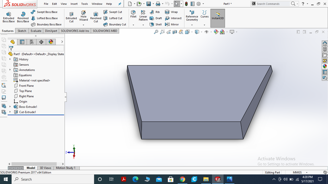
Then I extrude cut the slope.
DRAW THE HANDLE.
Draw the small rectangle at the center with some calcualtion.
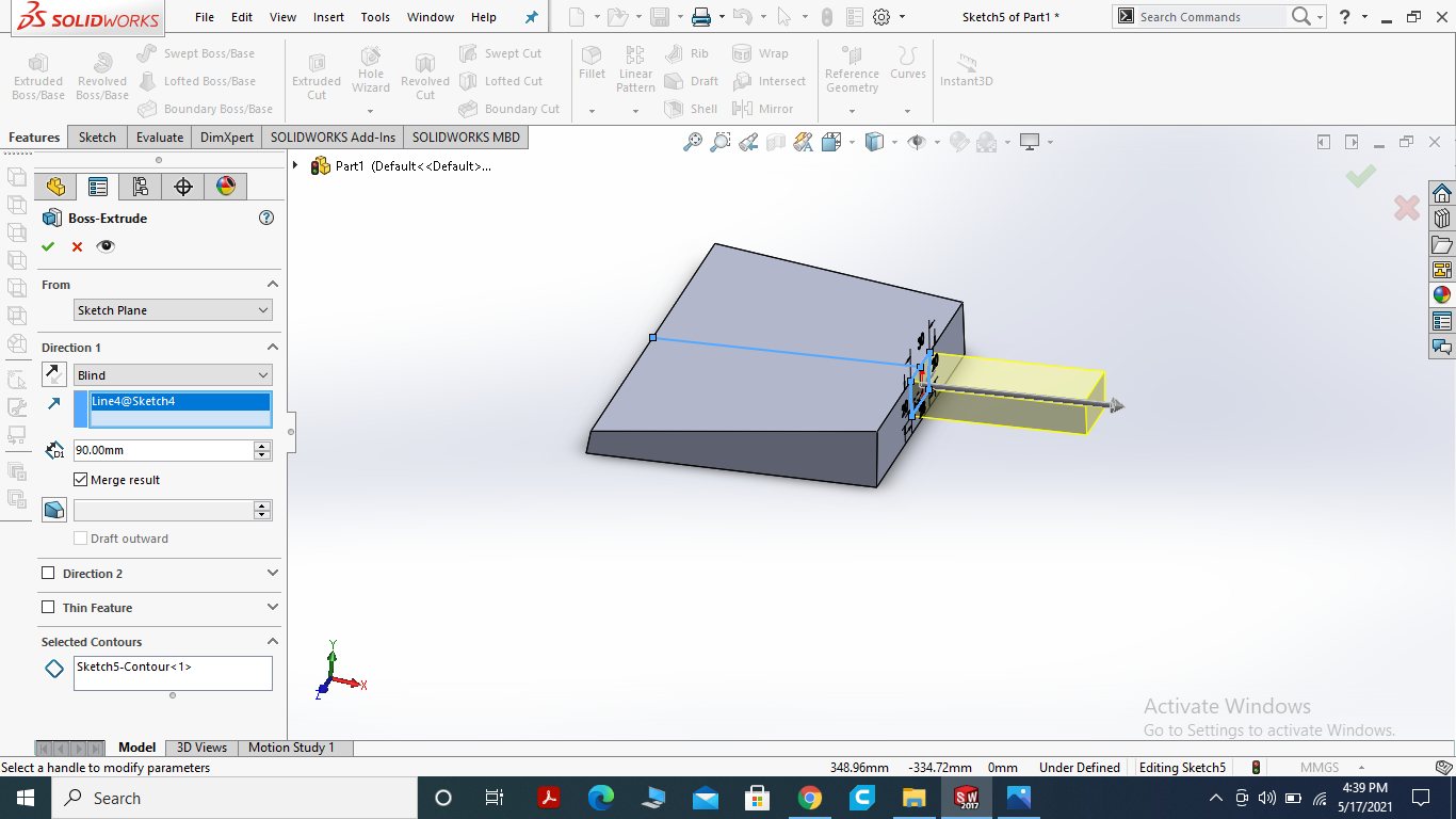
I extrude boss the part for handle.
USE FILLET COMMAND TO SOMMOTHEN THE CORNERS.
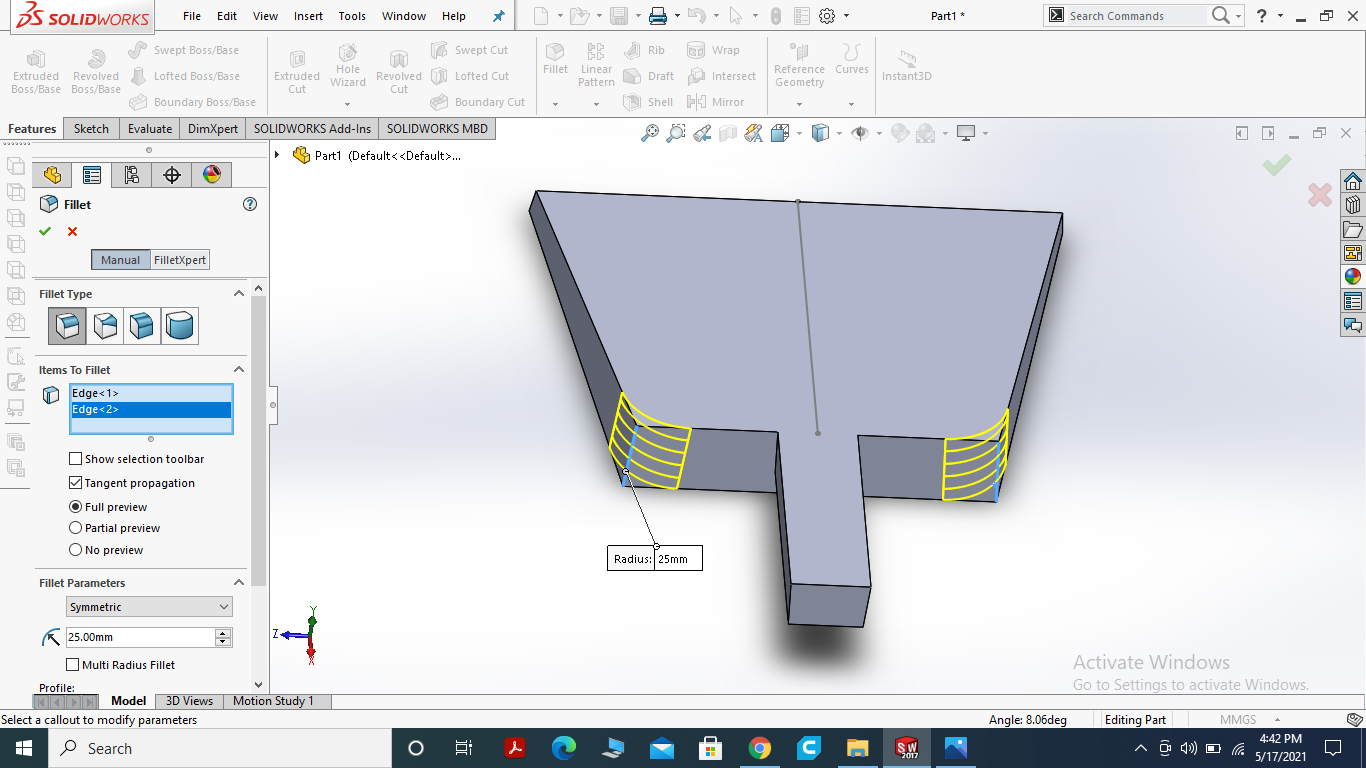
Using fillet command at the edges to made the side smooth.
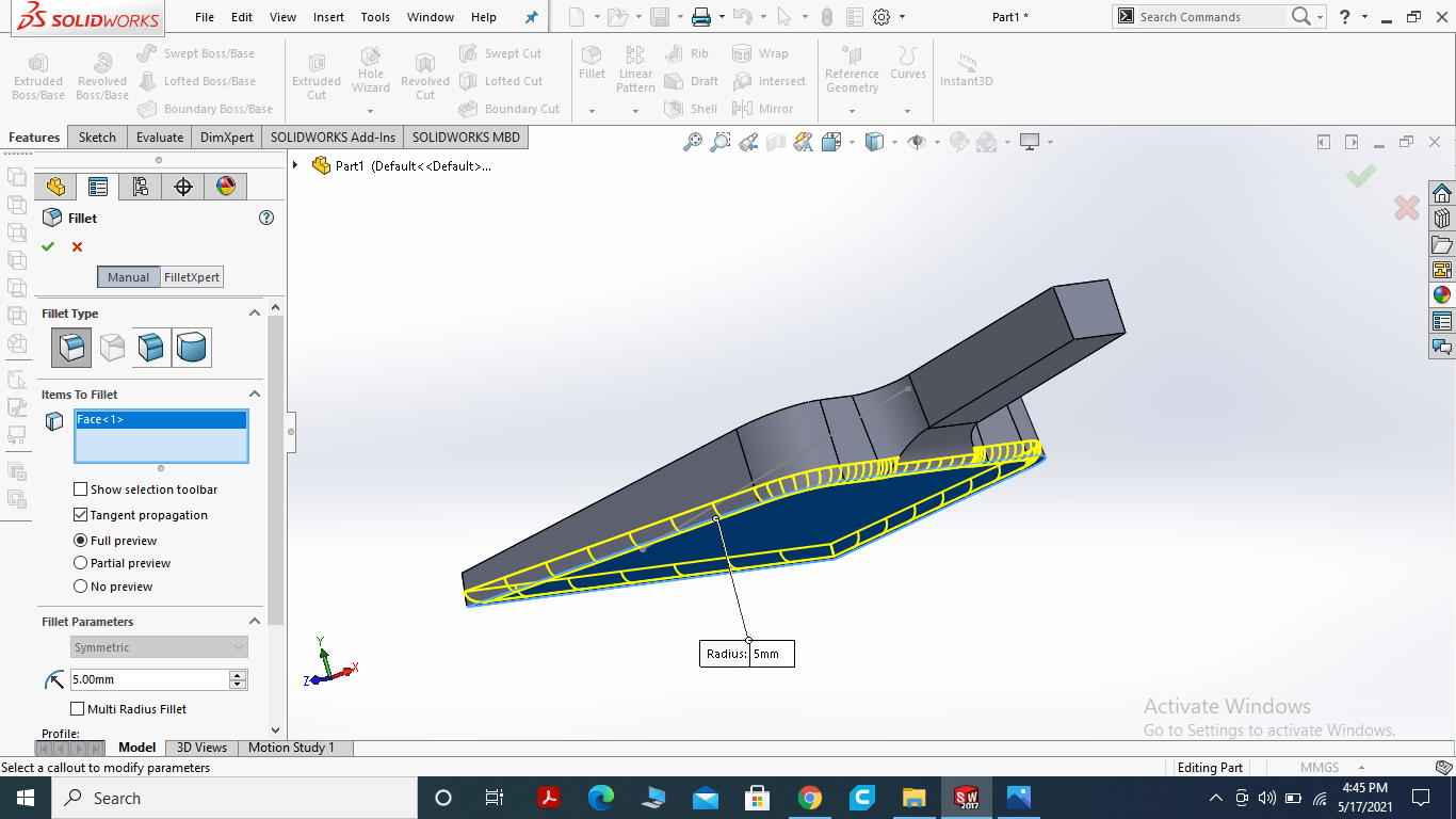
filleting the every side, corner and base of the part.
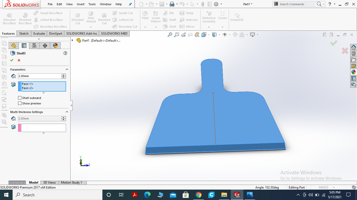
Here, I used the shell command with 2mm to delete the one face and making hollow inside it.
NAIL SLOT
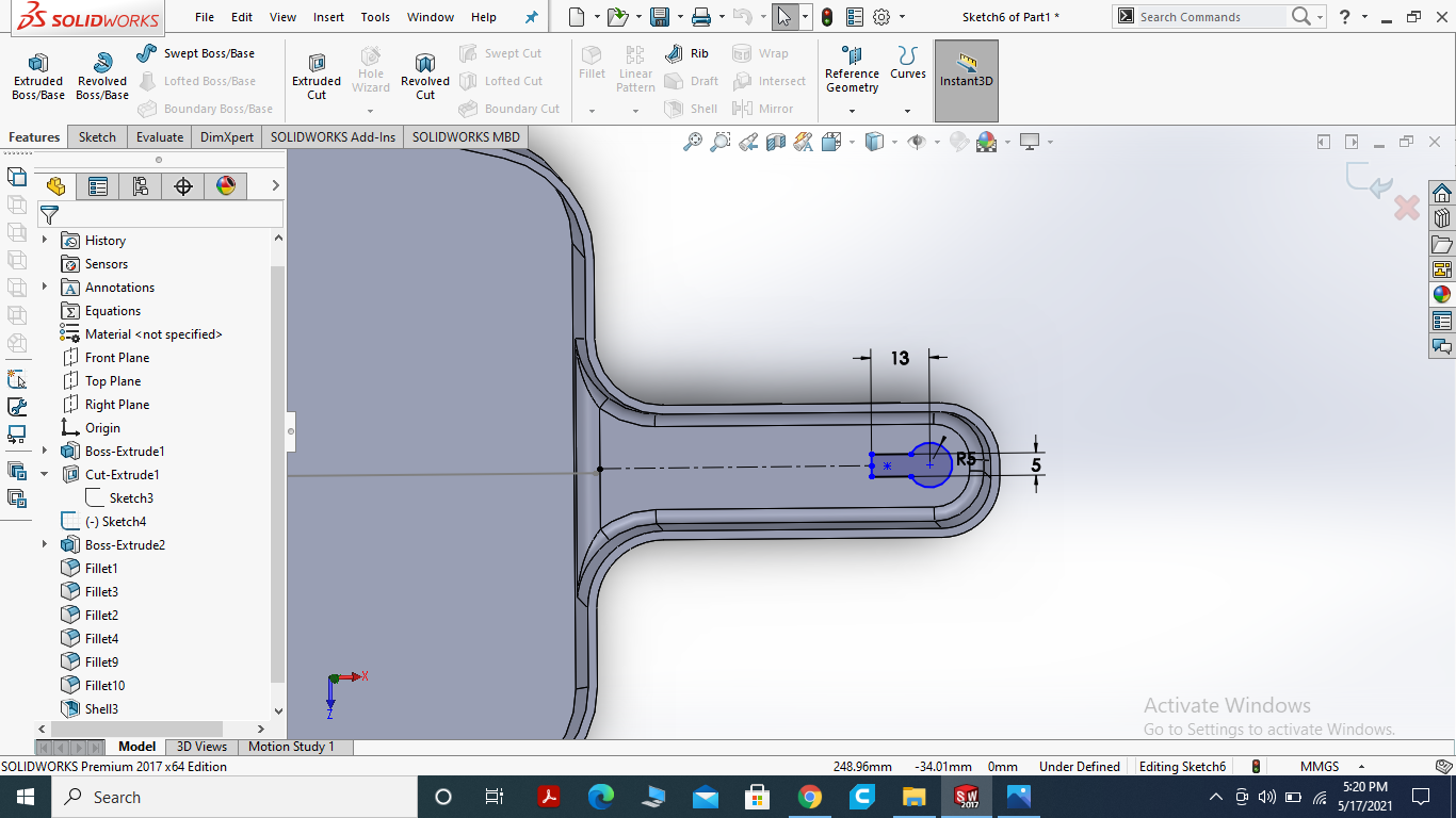
for hanging the dustpan I am making a nail slot for hangging dustpan with wall nail.
Use the Extrude Cut Command for Nail Slot.
FINAL RESULT
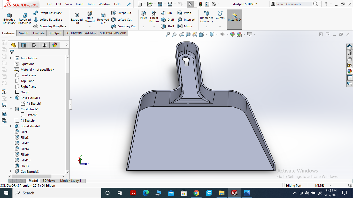
This is the final look of dustpan which I designed on solid work.
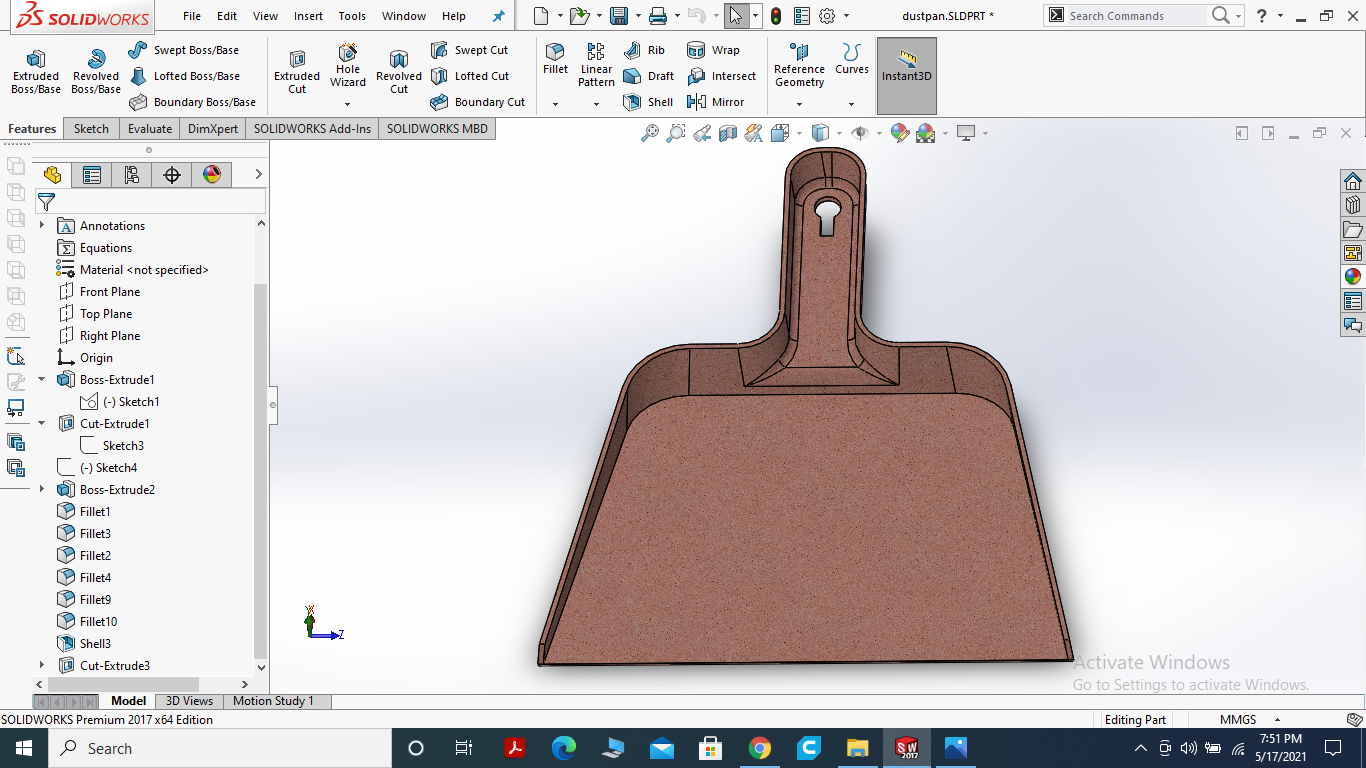
I used real time graphics to have a real look and attrack the viewer.
OPEN VCARVE SOFTWARE FOR TOOL PATH GENERATION AND SIMULATION
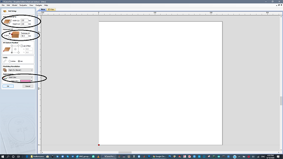
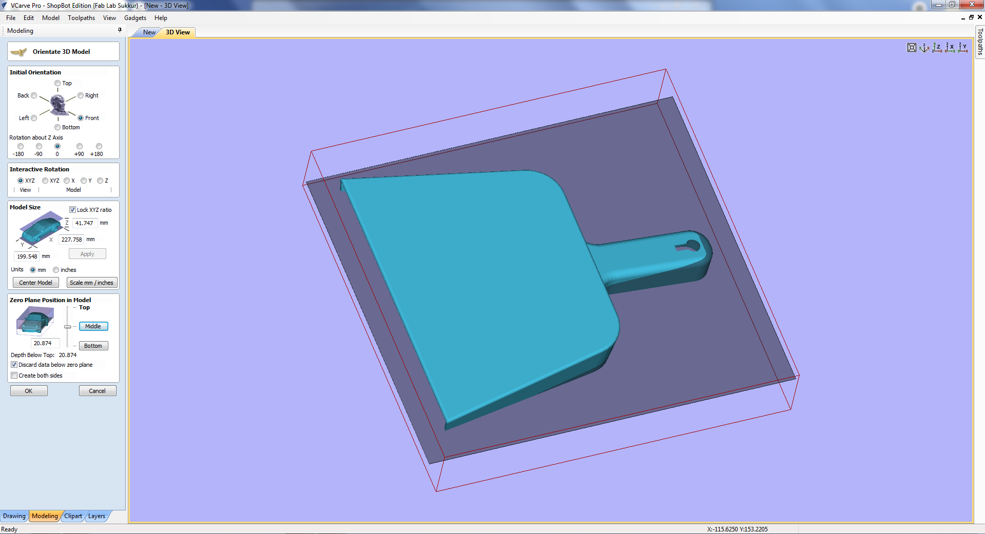
Open the Vcarve software and put the size of object that we have designed.
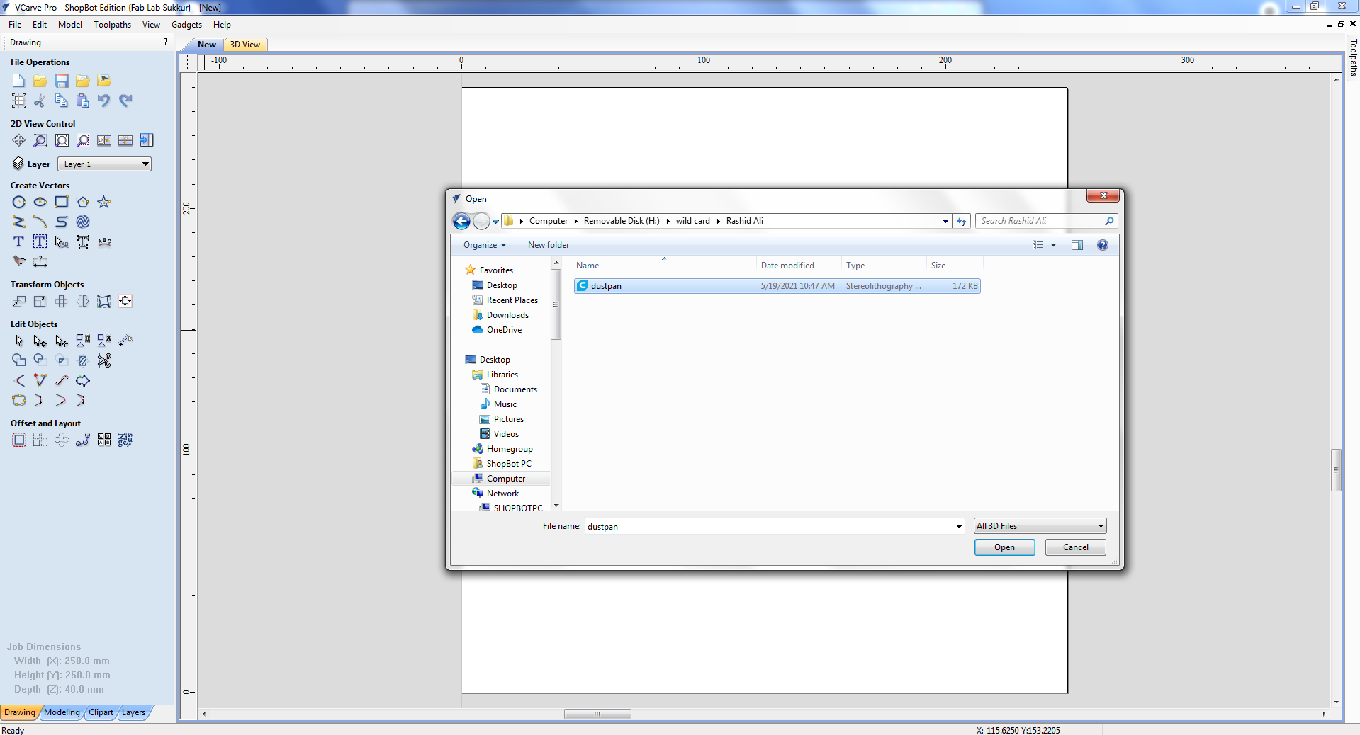
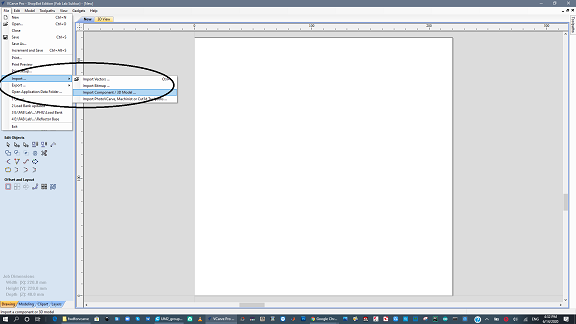
Then import the .stl file into Vcarve.
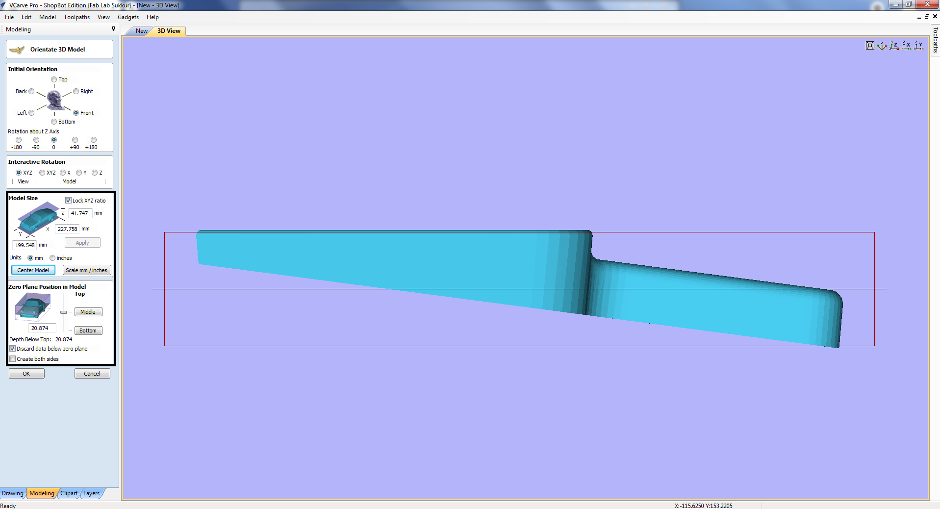
After importing the 3D model, click on "center model" and uncheck the "discard data below zero plan".
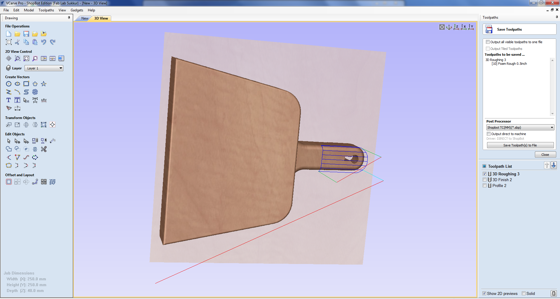
CREATE TOOLPATH FOR ROUGHING
click on center in model size and select the middle in zero select plane position.
Set the safe Z-axis then click ok. After that choose the bit for this toolpath.
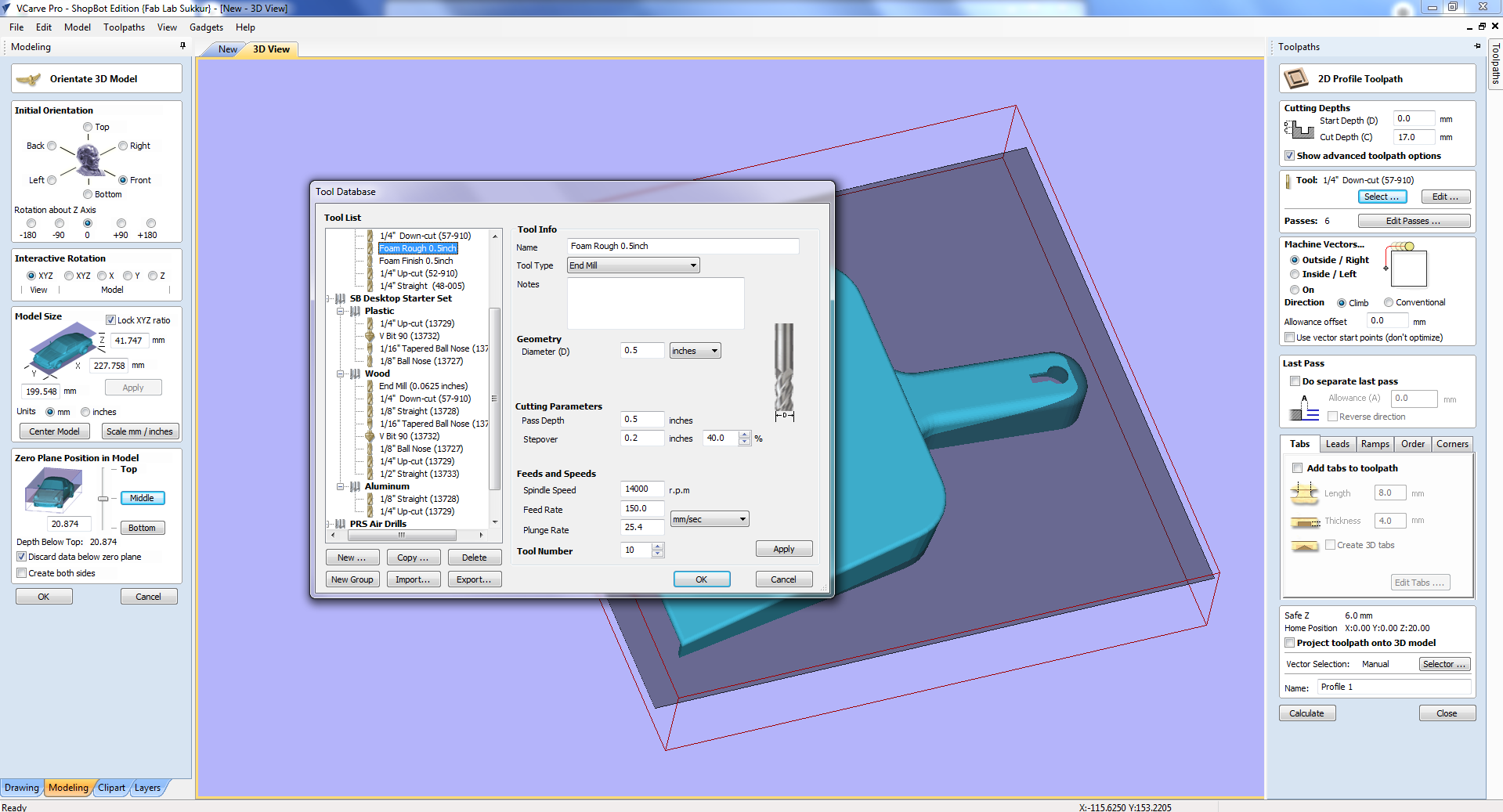
For this task i am using "Foam rough 0.5 inch" tool.
CREATE TOOLPATH FOR FINISHING
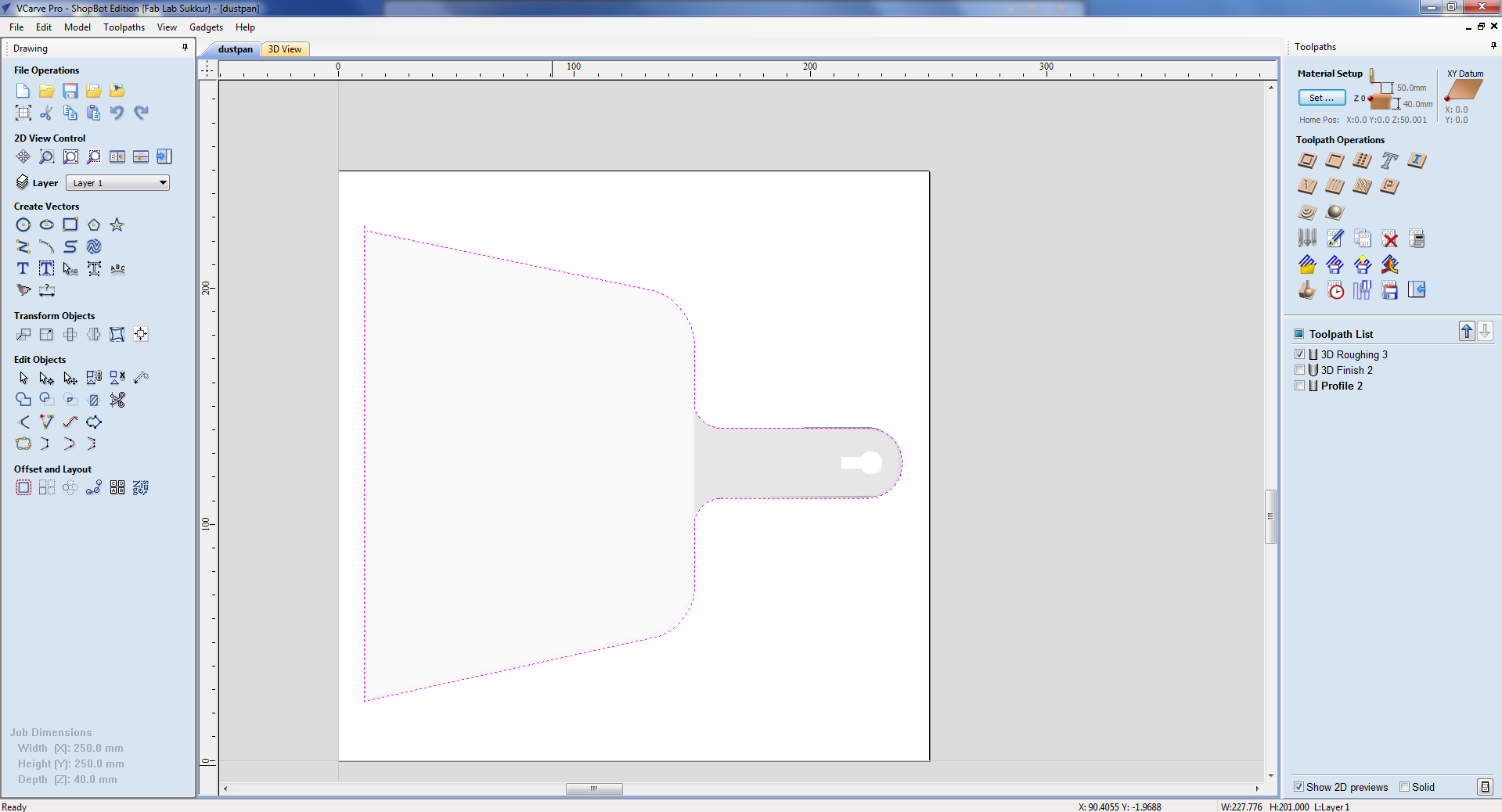
I draw a drawing above the object select the drawing pick the pencil and draw the lines.
Select the Finishing toolpath then select "foam finish 0.5inch tool" and generate the tool path. Run the simulation.
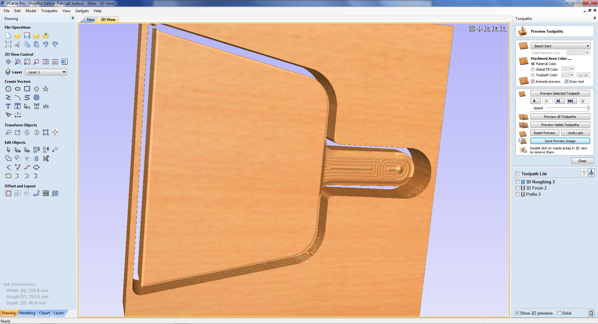
This is the final result of simulation.
CHANGING THE TOOL OF MACHINE AND DOING Z-AXIS ZERO
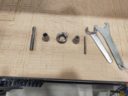
After generating shopboat file, first thing is to change the tool bit of machines. Remove the old tool bit and insert the foam rough 0.5inch tool bit. Also the colit of machine. After Changing the tool bit now it time to origin.
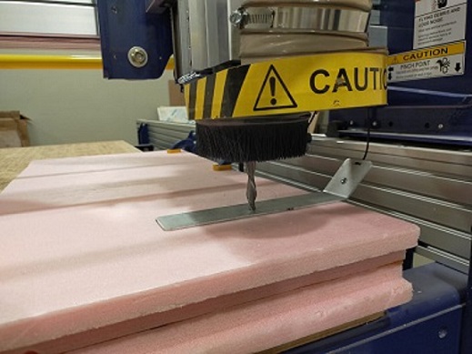
First set X and Y by jogging the machine. When tool bit is start of foam make the X, y zero. Then it is time to make Z zero. For that we use the Z-axis build plate. Put this plate exactly underneth the tool bit and click the z axis zero on software. It will automatically calculate and make the Z axsis zero.
MACHINING
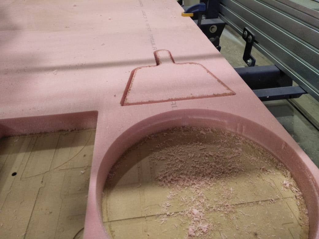
setting all it's axis, give the machine rough file and select the cut. Machine start the rough job. After rough is complete follow the above steps to tool changing then making z zero using build plate. then give it finishing file and in list cutting file.
This the final result after all tool paths.
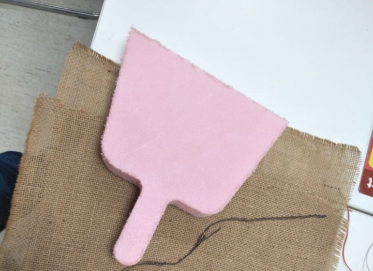
FABRIC AND COMPOSITE
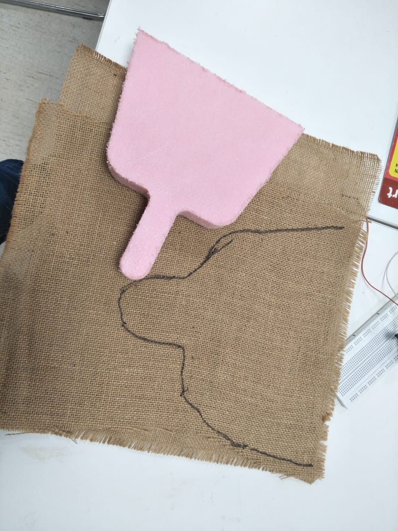
I am using double layer fabric. Layers are at 45degree tilt so holes will not be visible. I also made a drawing on fabric for getting perfect sizing.
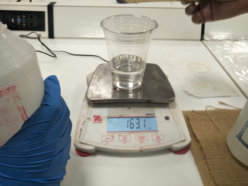
The ratio of rasin and harder are 2:1. means 100 grams of resin and 50 grams of hardner. here I took 163 grms of risen.
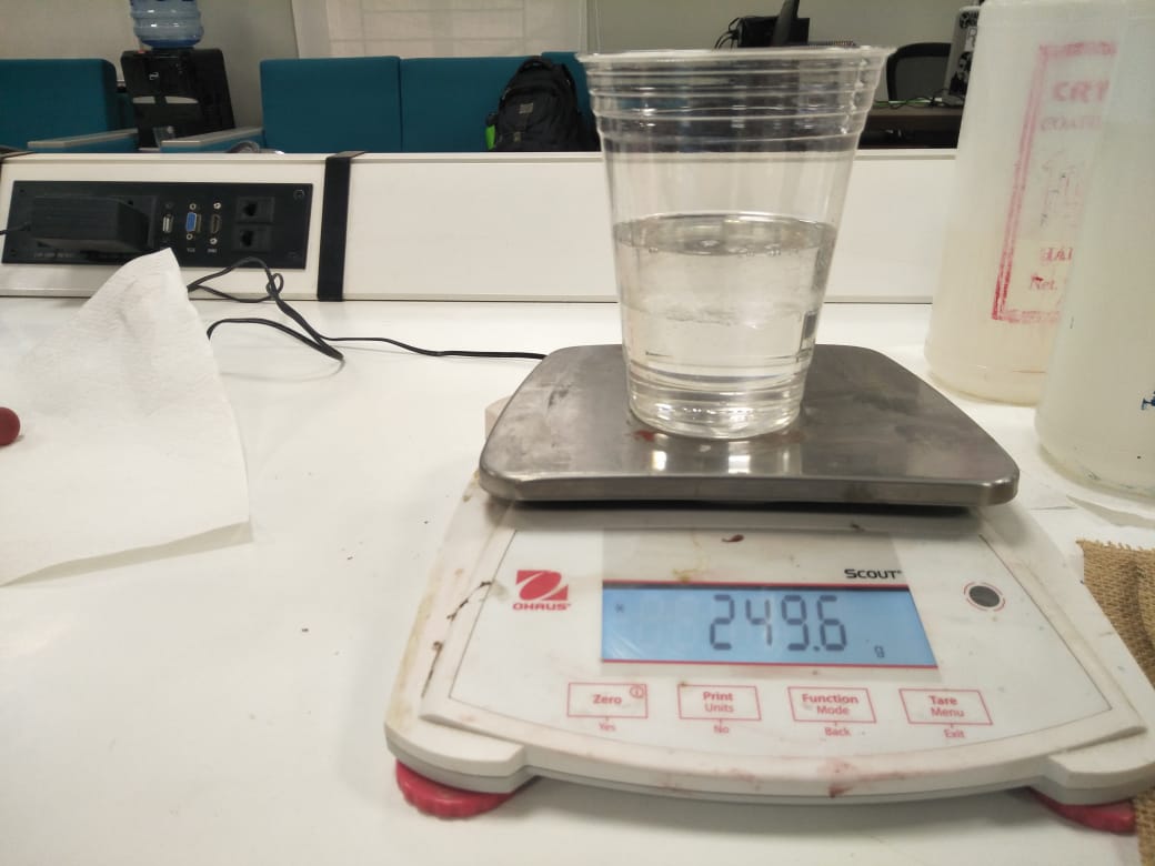
I added approximately 87 grams of hardens.
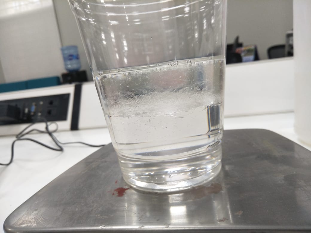
Here, is the mixture of both hardens and risen.
The next step is to cover the object in plastic sheet.
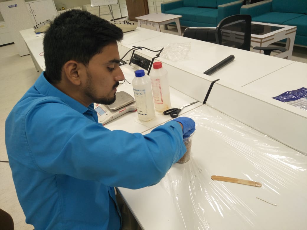
After mixing the risen and harden with 10-12 minutes when it heats up then pouring the fabric inthe chemical.
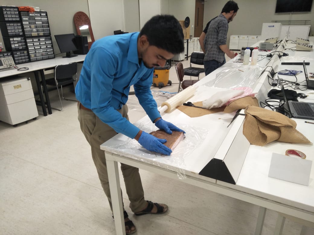
Cover the mold with fabric plastic layer. Then put resin dipped layer on mold and again put plastic layer on it.
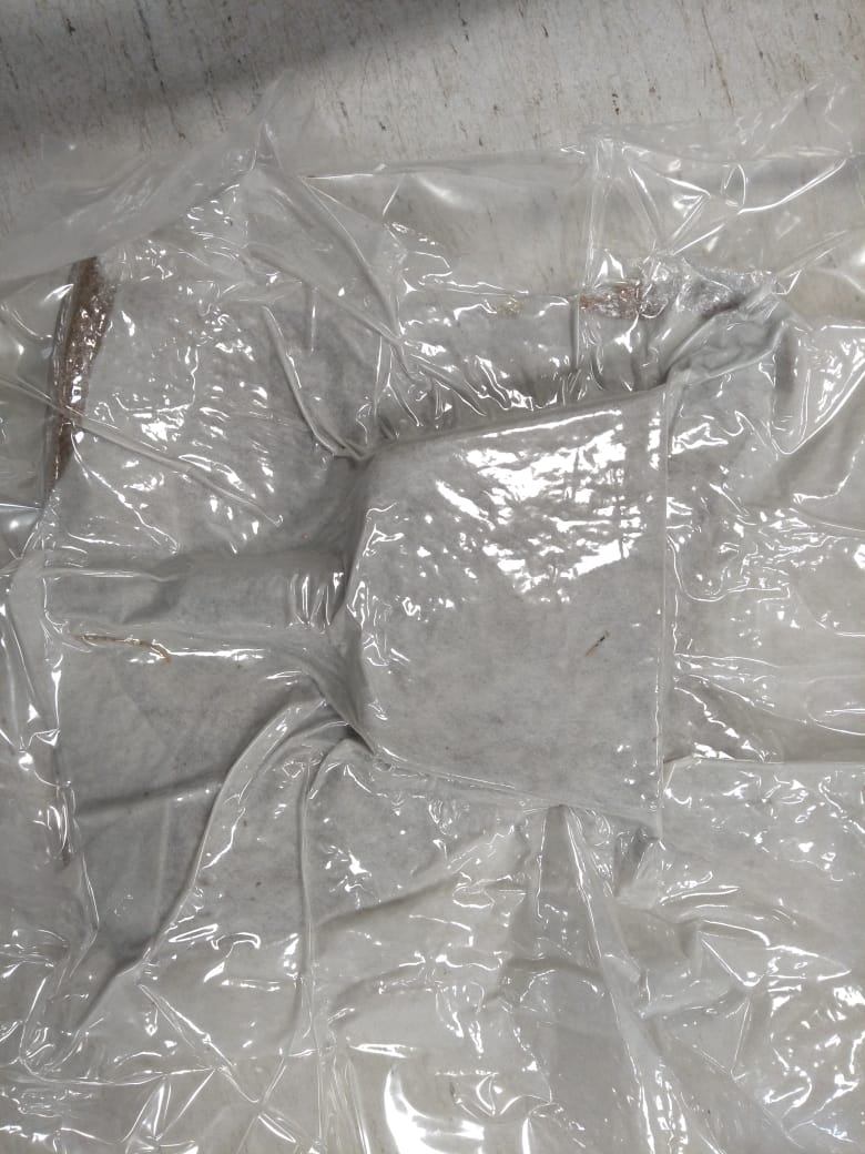
Put whole experiment into air tight bag which is used as vaccum.
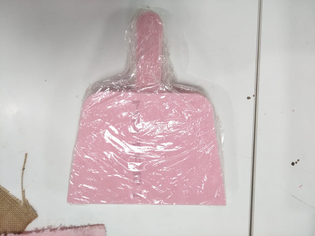
FINAL RESULT
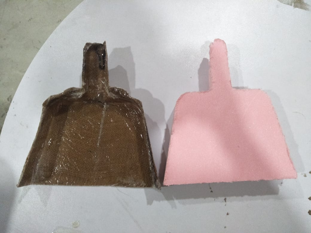
mold and composite final result.
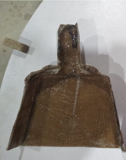
composite final result.
Propeller Led Pendulum Clock by Engr. Rashid Ali is licensed under Attribution-ShareAlike 4.0 International![]()
![]()
![]()