A multimeter is an electronic tool used to measure voltage, amps and resistance across circuits.
By attaching two leads to different parts of an electrical system.
We decided to check component in echo-hello world circuit using multimeter to confirm the values of components and to check either they
are in working condition or not.
This tool may also be known as a volt-ohm meter or volt-ohm-milliammeter (VOM).
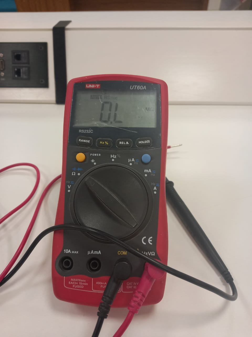
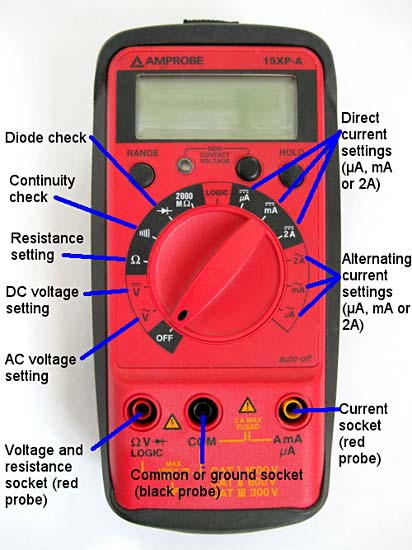 fig: Picture of Digital Multimeter.
CONNECTIVITY CHECK
After milling and soldering first task is to check the connectivity of circuit. If any line will not be attached correctly to the IC or any component, our circuit will not work Properly. In order to check the connectivity, rotate the dial on multimeter to diode and select the beep button as shown in above figure. Then put anode and cathode of multimeter to that line which is supposed to be connected. If you hear multimeter beep then this line connection is ok, else there is no connection.And also recognize any short short if exist in the circuit.
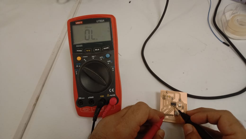
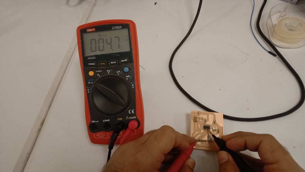
fig: showing the connectivity test.
LED CHECK
Second test is to make sure that LED is correctly soldered and polarities of LEDs are correct. In order to test the LED,rotate the dial on multimeter to LED and put cathode to ground and anode to the supply side of LED.If led glow then LED is perfect in position. If LED do not glow, check the soldering and/or the polarity may be reversed.
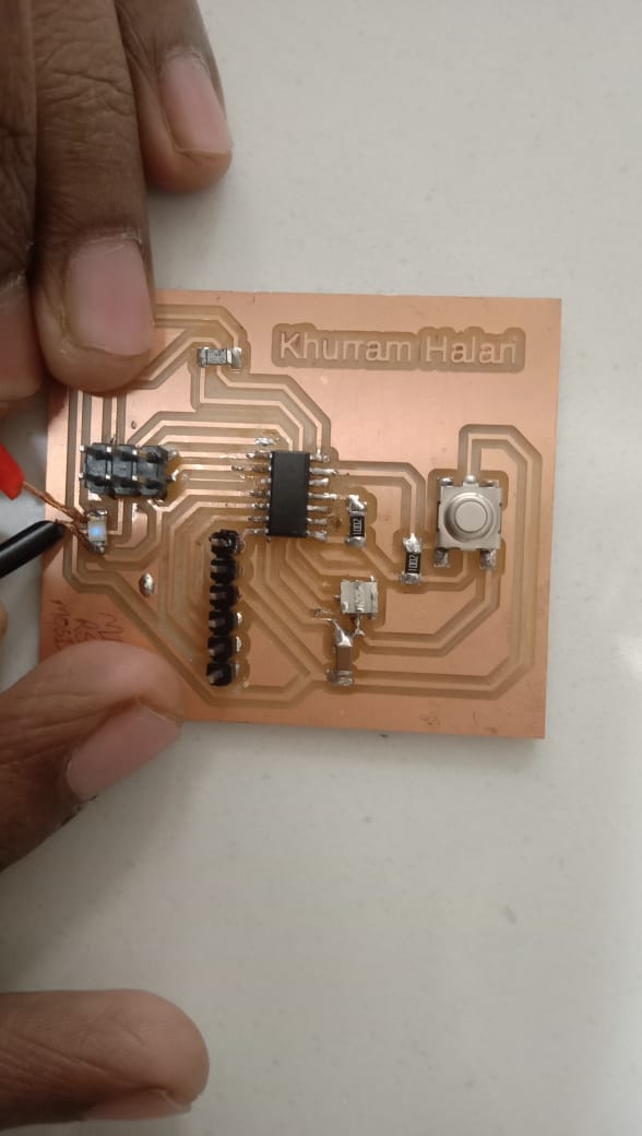
fig: showing blinking LED.
Resistor Measurement
As we are using 3 resistors in the hello-world board having value of 10k ohm and one have 100 ohm so it is necessary to have resistors placed in approriate place for proper functioning of the board.
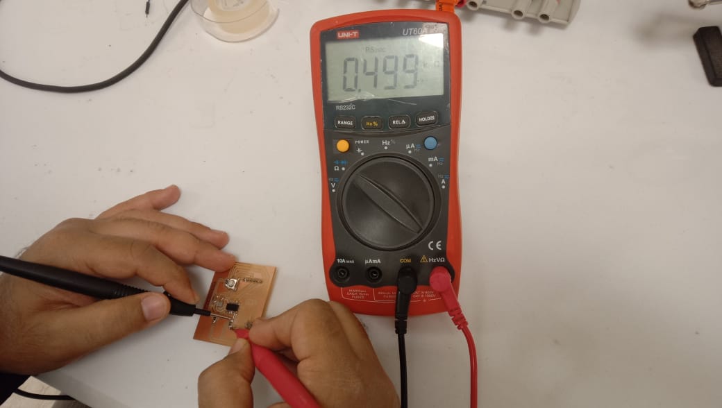
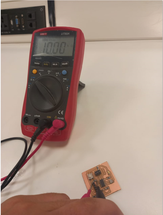
fig: showing the values of resistors .
Individual Assignment
As the individual assignment was to redraw an echo hello-world board. Add a Button and LED (with current-limiting resistor) check the design rules, make it, and test it.
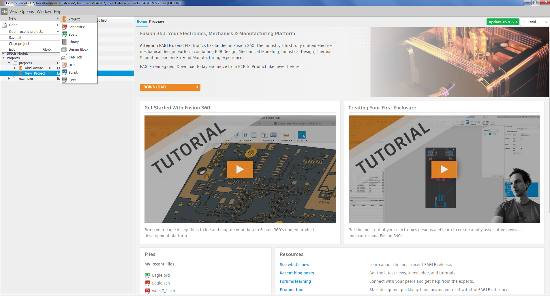
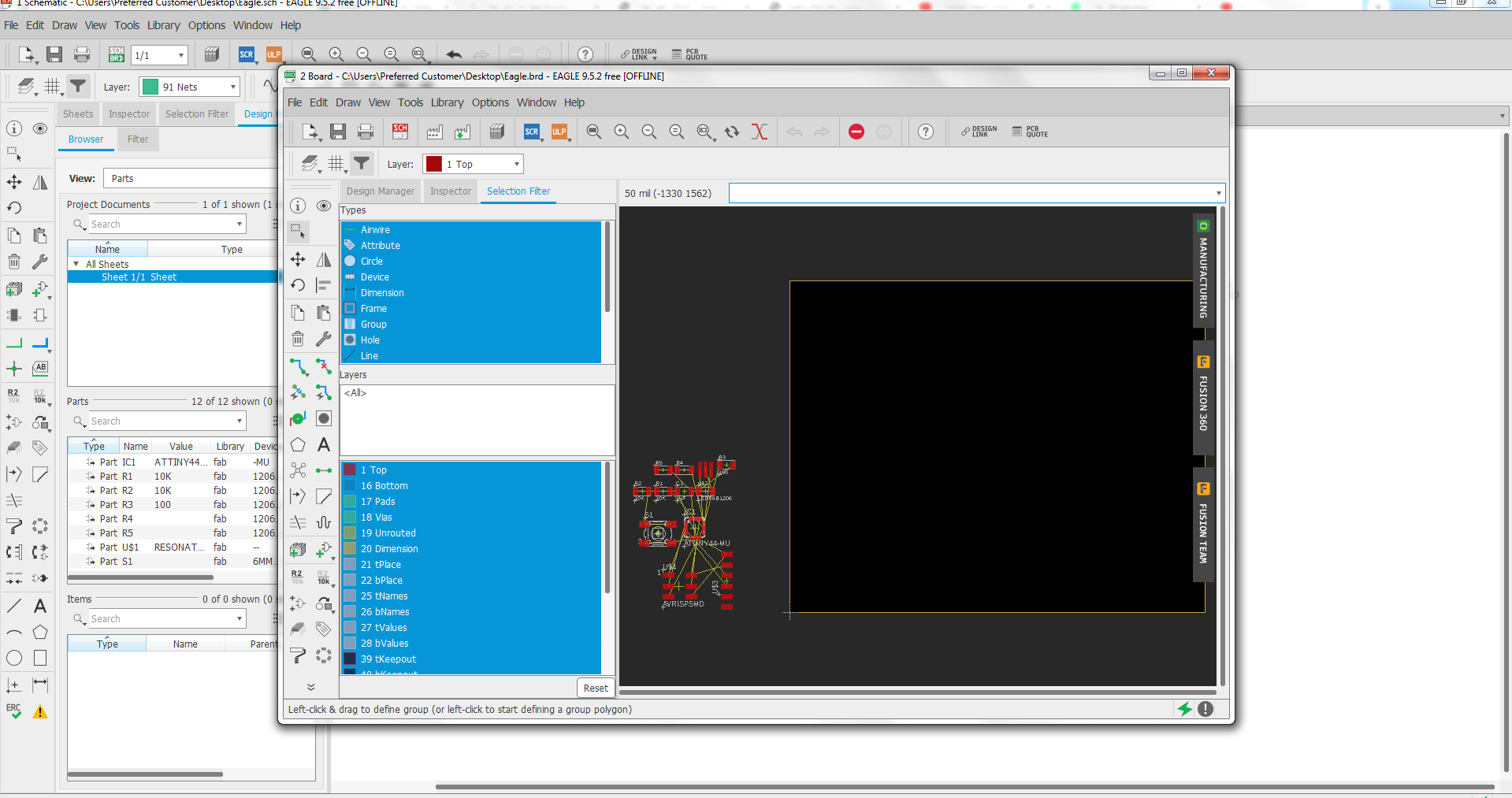
I start with the EAGLE 9.5.2 (Easily Applicable Graphical Layout Editor) to redraw and design the circuit. First of all I watch videous on youtube about different components use in the Eagle and the application of the Eagle software. My Instructor Guide me and advice me to first start with simple desig and then go toward the assignment.
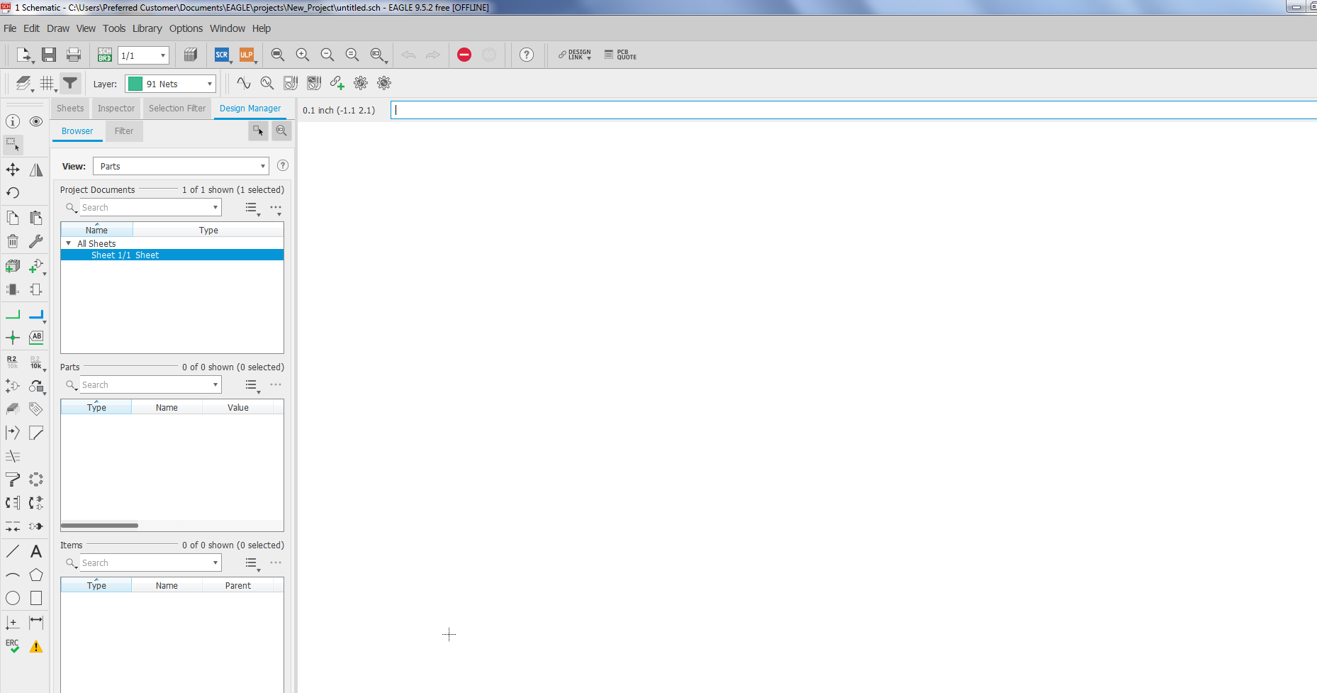
Open the Eagle software already Installed in the system
After that Add the fab library
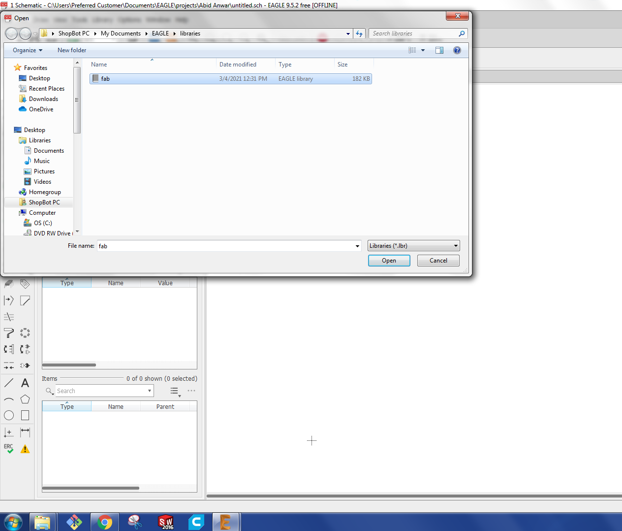
Adding library
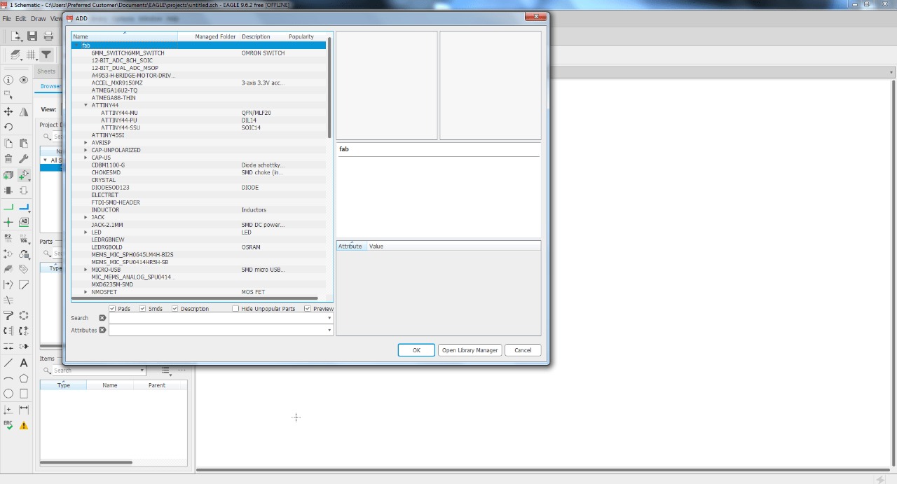
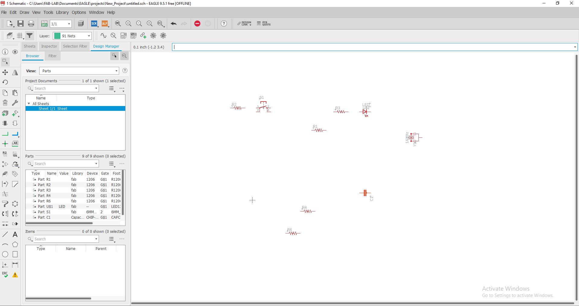
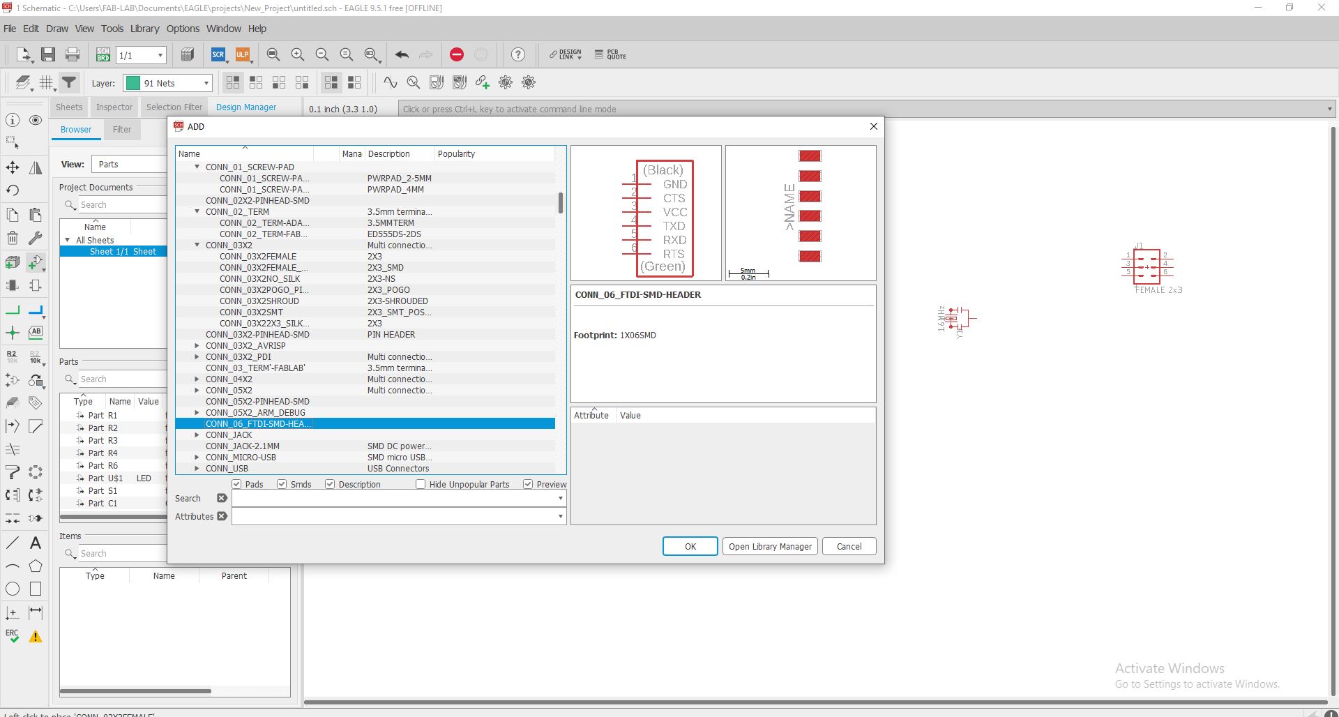
Once the library added I start to add Components
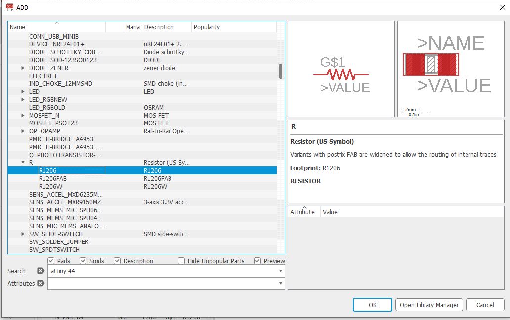
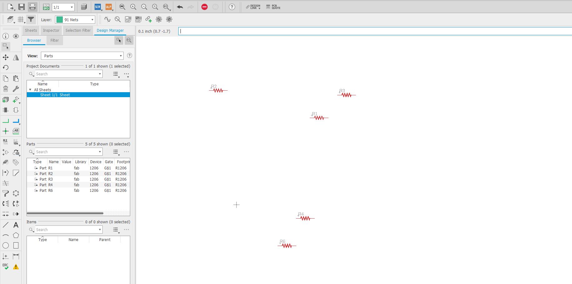
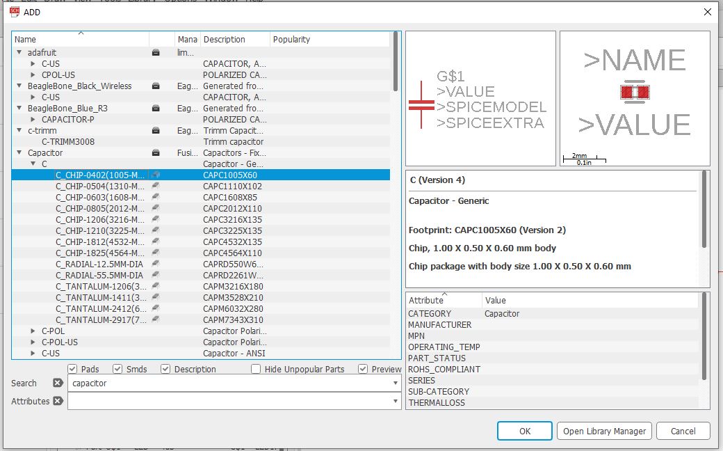
Adding the resistors
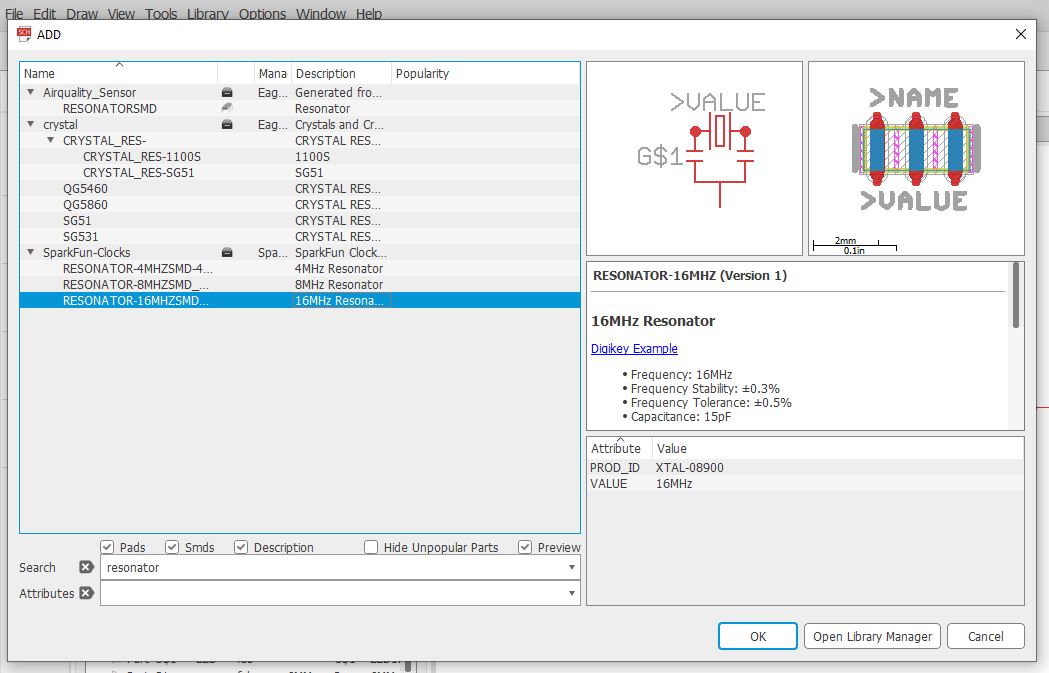
After that I add the LED, Switch,Capacitor and resonator 16 HZ crystal as:
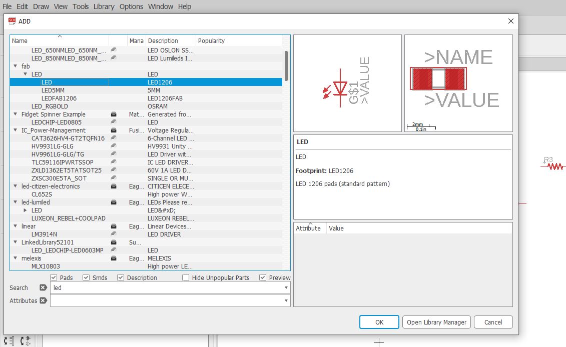
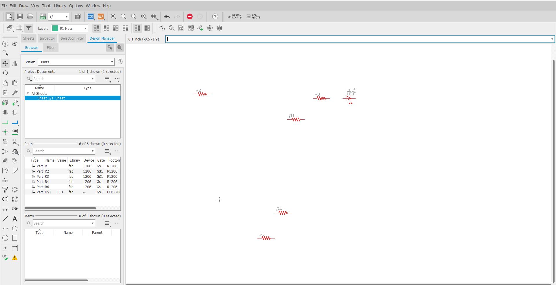
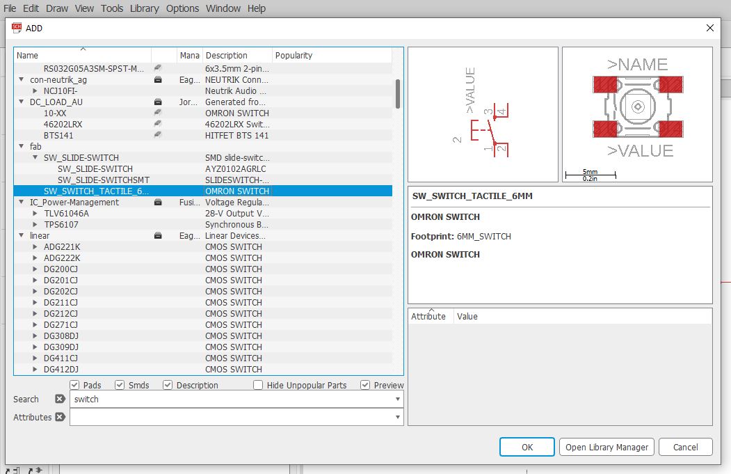
Adding the LED and Switch
Now I add the Header which were 3*6 and 1*6
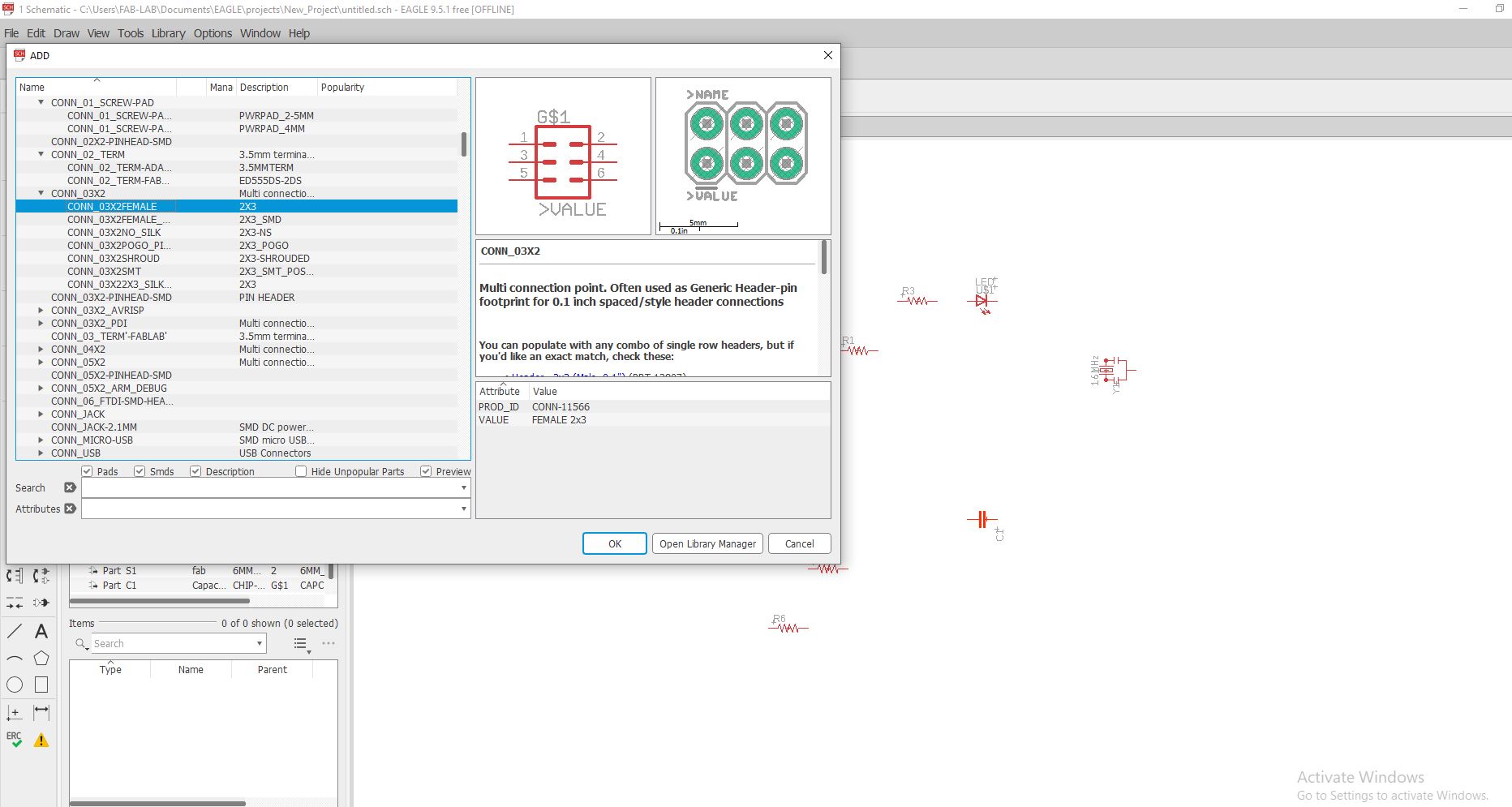
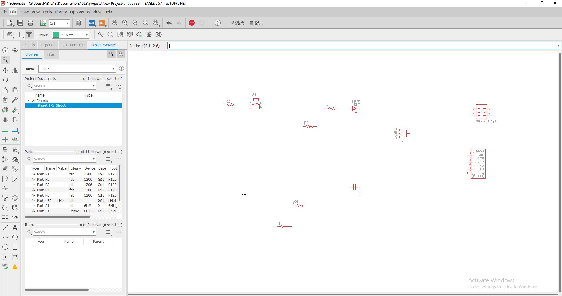
Adding the Headers
At Last I add the Attiny 44 as:
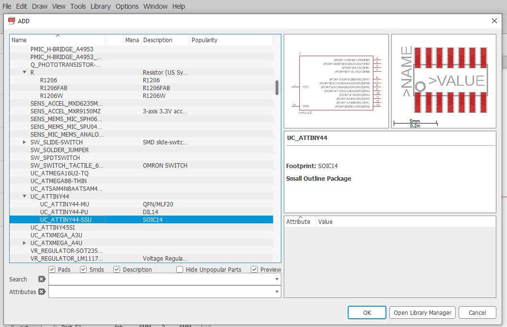
Adding controller
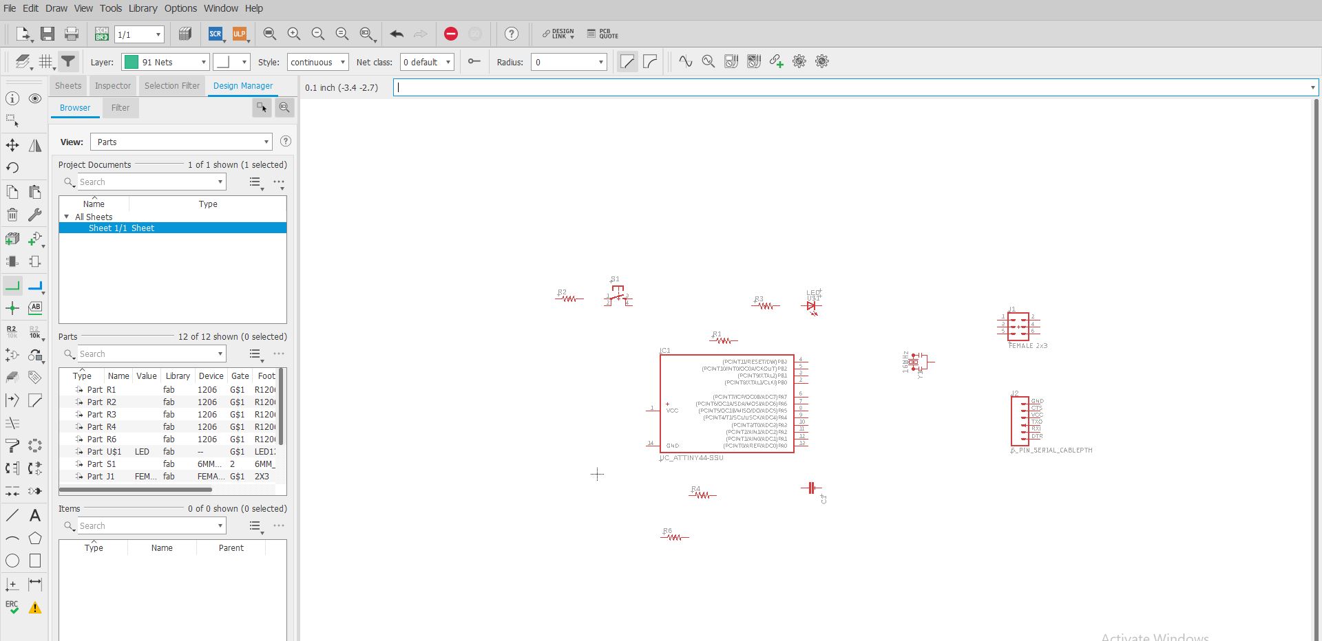
Now I start netting and Connecting Components togheter by changing the name as:
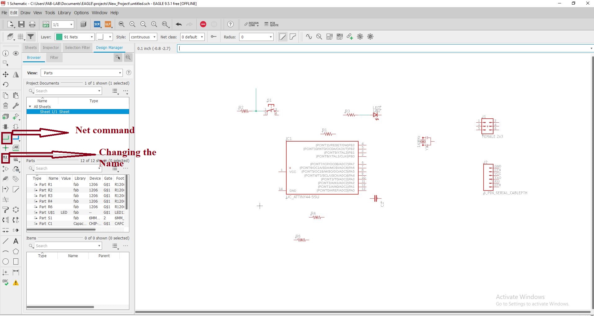
Neting and connecting the components.
As I add all the necessary components required for the circuit. And use the net to connect different required components togheters and also rename the components to connect togheter .
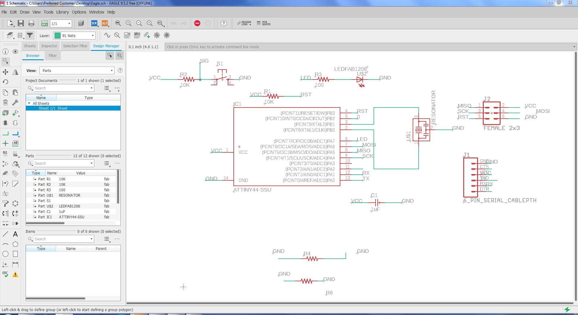
Fig: Schematic daigram of the circuit
CHECK ERC
After adding all the necessary components and getting the schematic ready we are supposed to check ERC i.e Electrical rule check characteristics, From the ERC I got no errors but few warnings and in most of the cases warnings are appeared due to pins which are left un used in the circuit. So far in my case the circuit is ready for the routing for achieving the board lay out. Here is the snapshot showing the ERC situation.
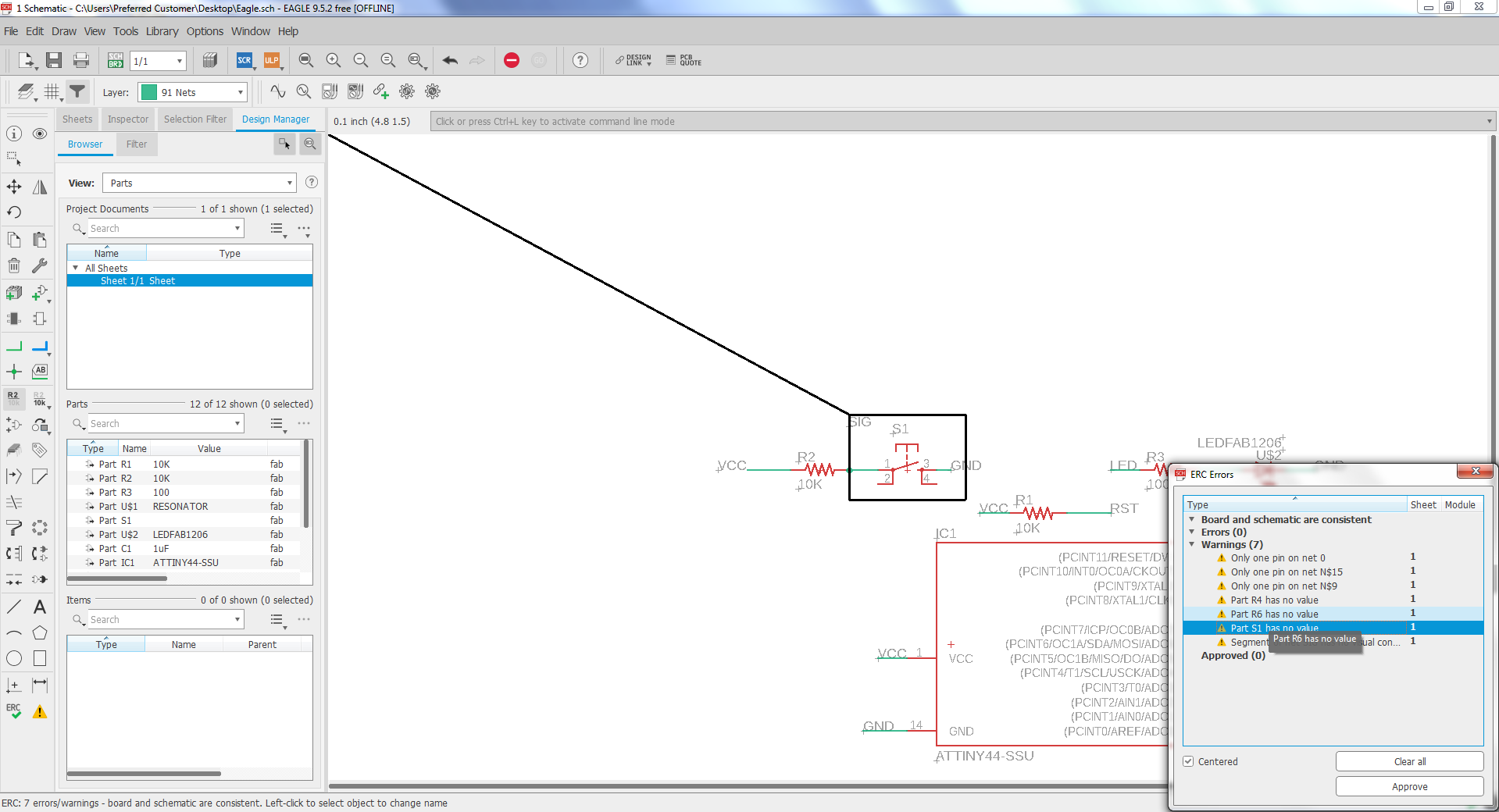
Fig: Screen shot of the ERC showing the warning sign.
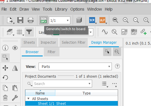
After checking the ERC and founding no error. I generate /switch to PCB Board view where i will be able to draw the Track for the circuit. I spent alot of time in the routing as to making the circuit as small as possible and to apply different approch for routing.
board layout
I move the component inside the area and arrange them in a way to have possible connection as:
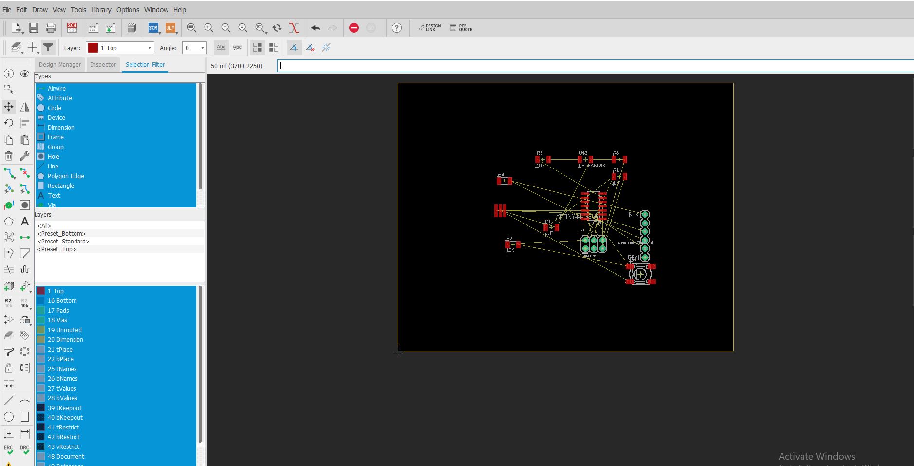
moving the components
Now I Start the routing the wire as:
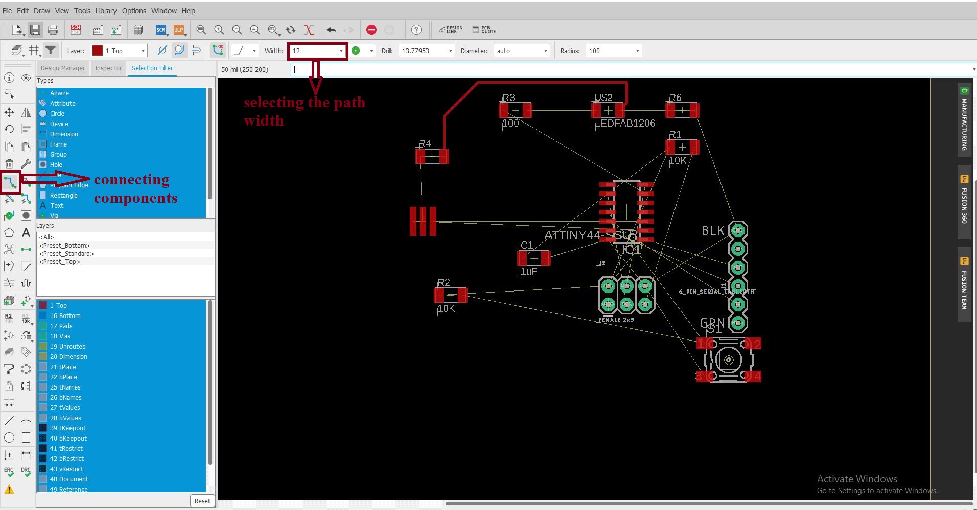
routing
Added My Name:
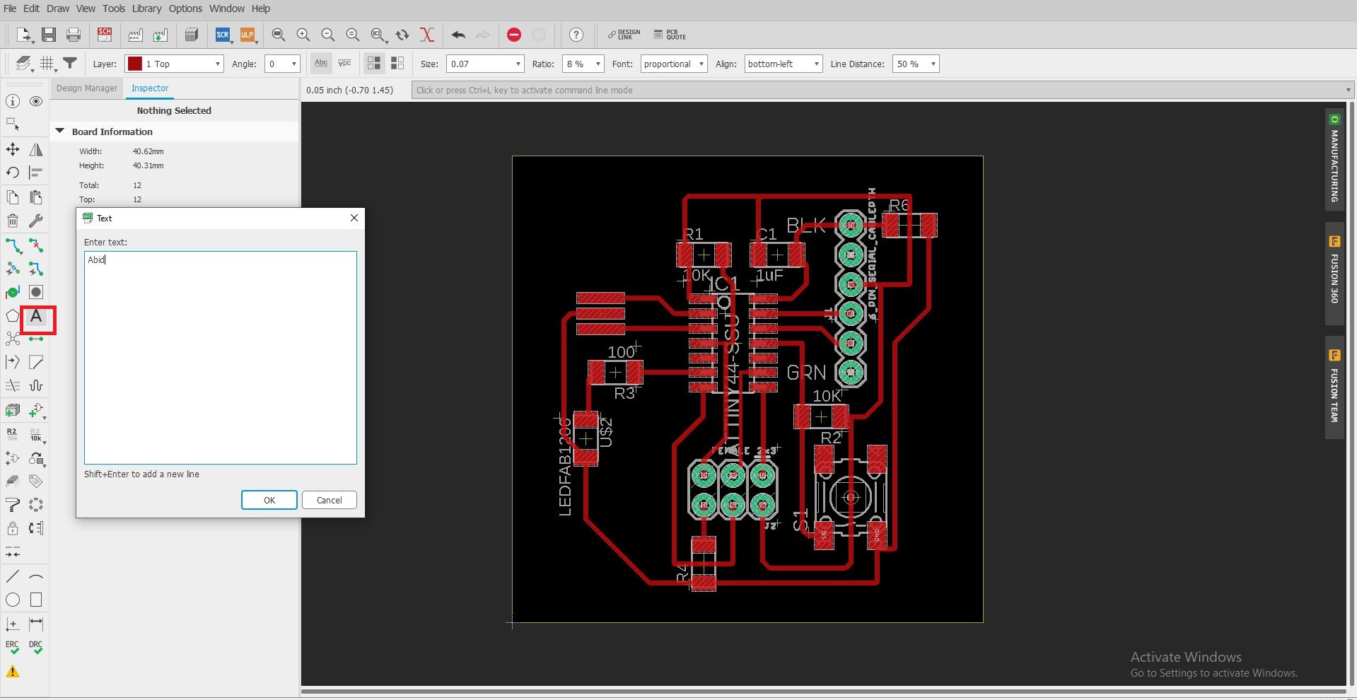
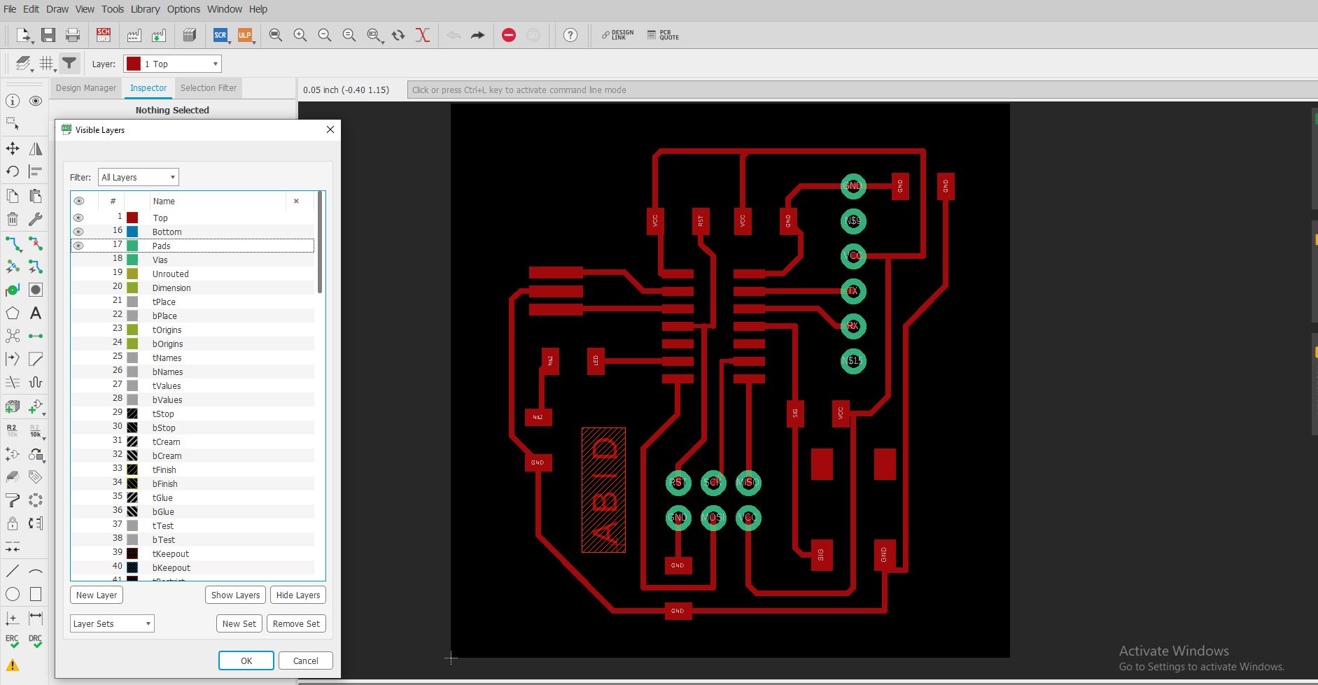
Adding name
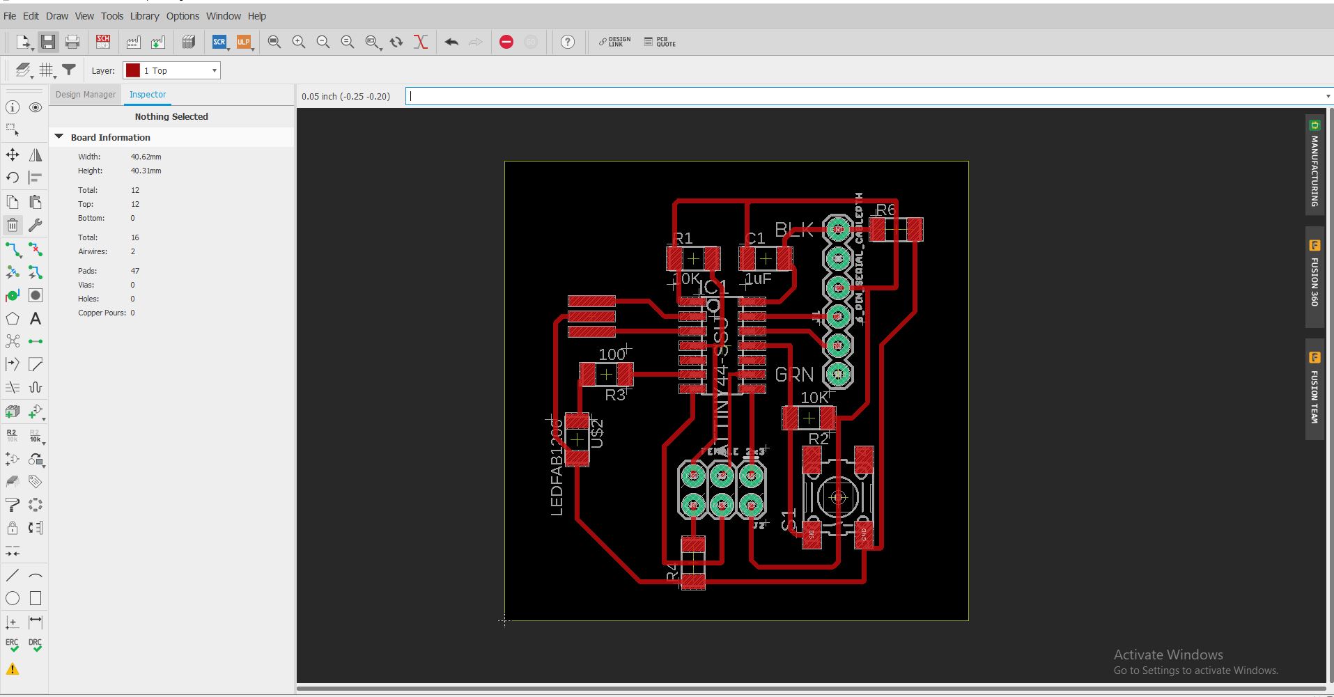
After routing in such away that the wire did not overlape the circuit the final circuit daigram is as.
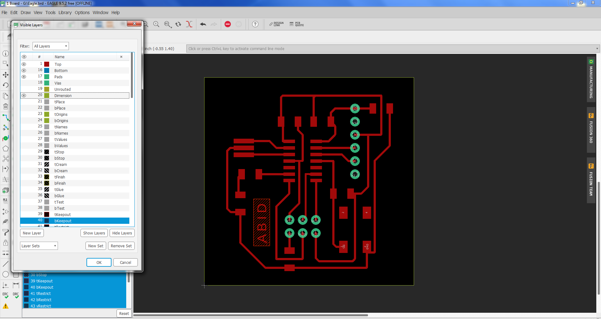
routed board layout
Saving the file as PNG
After completing the routing process I export and save the file in png for further process.
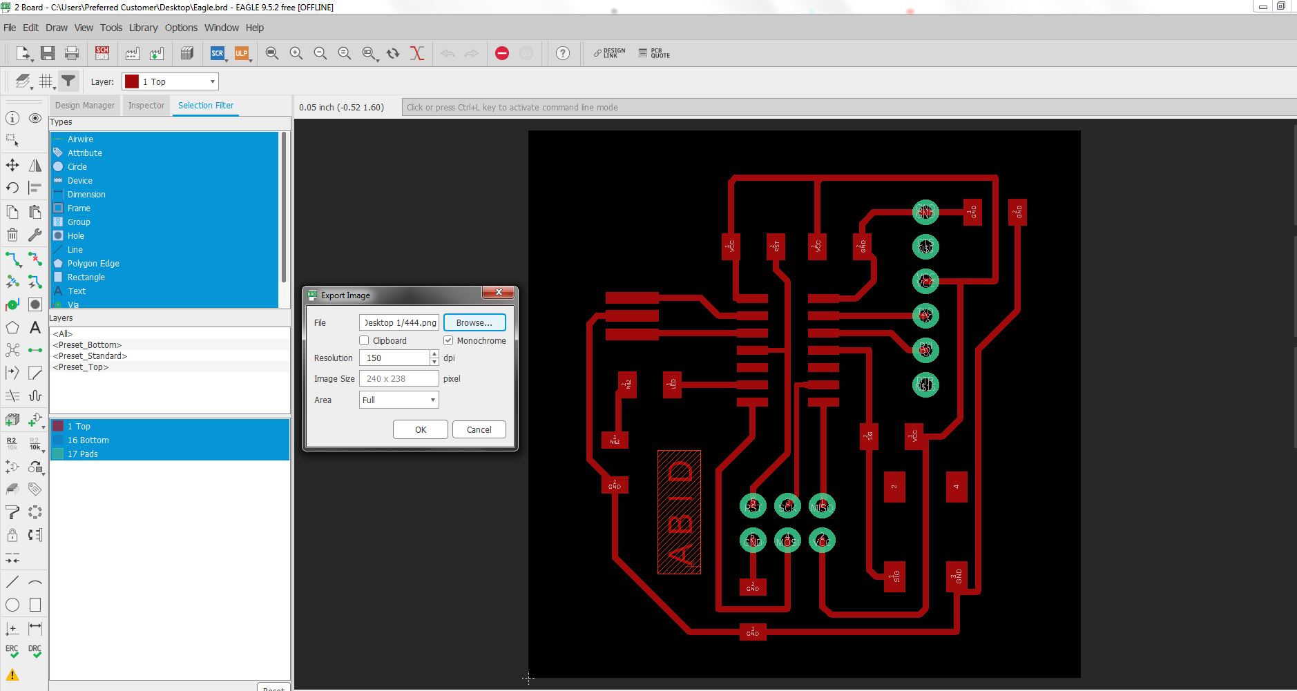
exporting as png
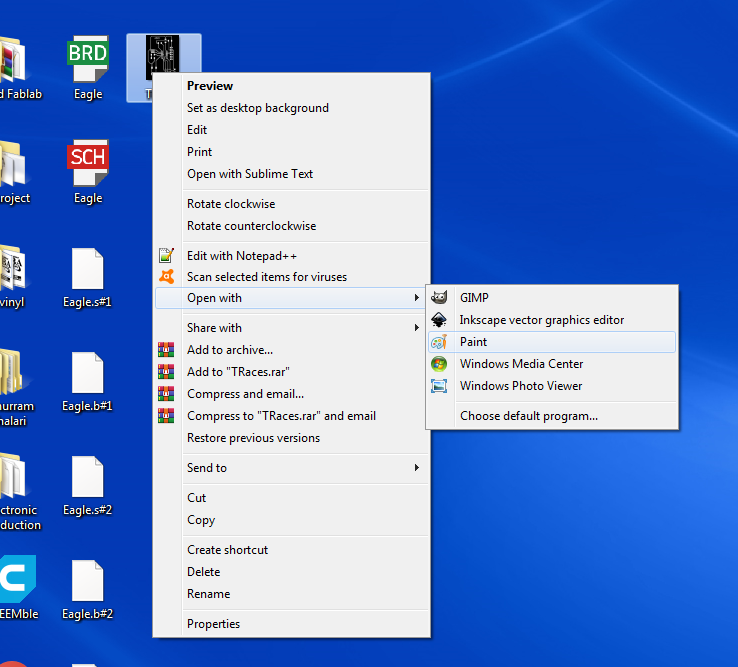
OPEN the png file in paint
Now I open the png file in the paint for making the traces , holes (dills) and border for the PCB
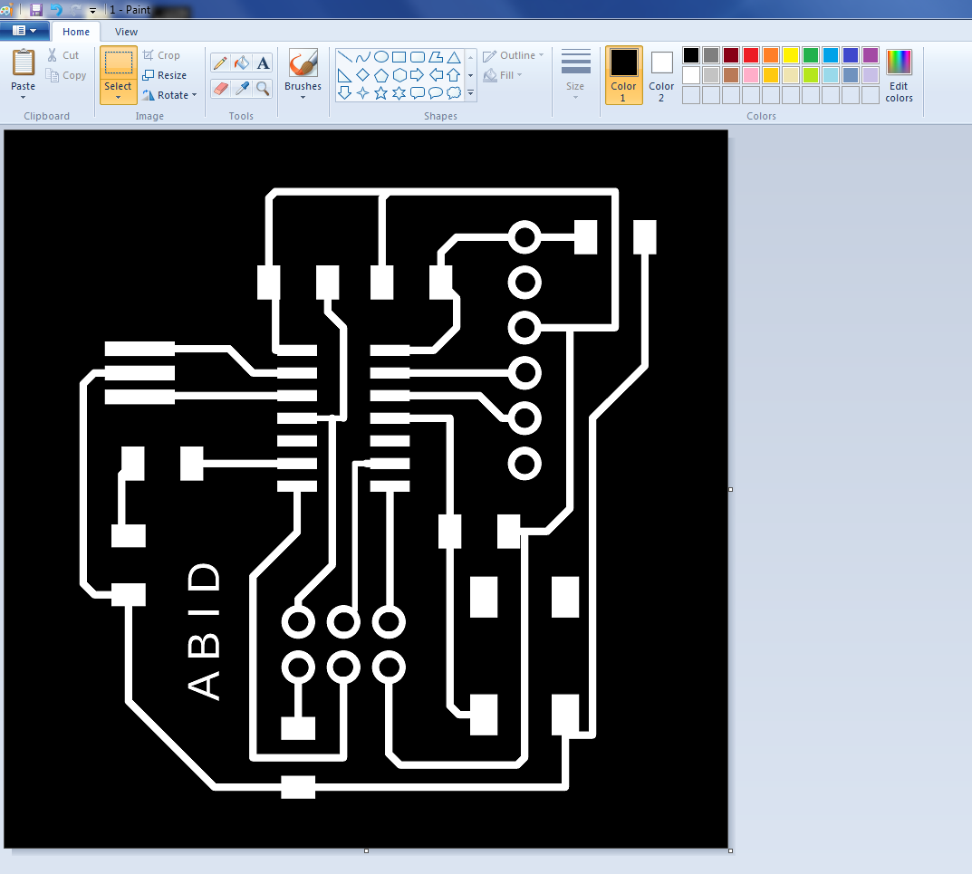

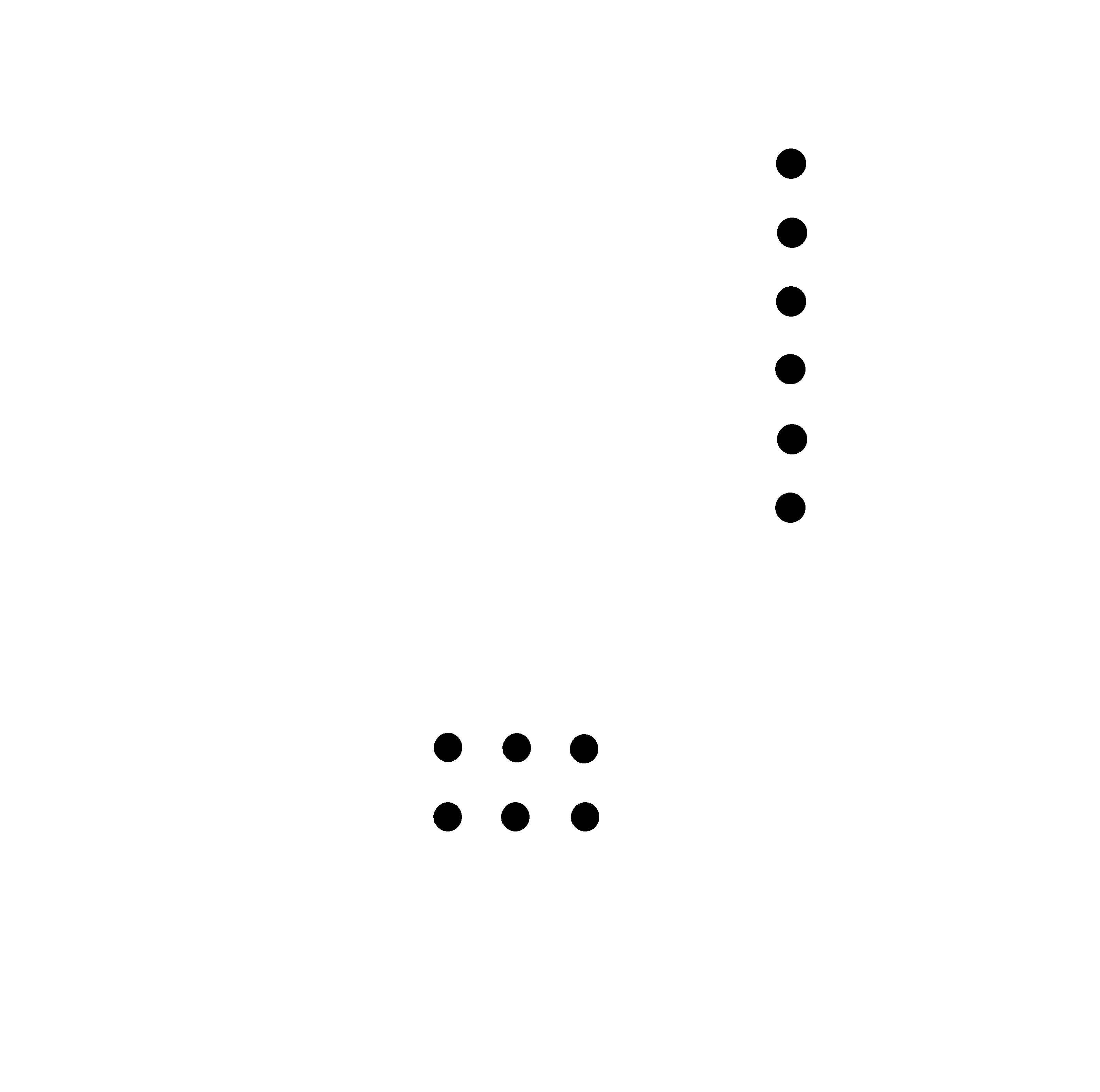
png file of the Traces, Drill and the Boundry.
Generate the .RML file
Now open all the above file in Fabmodule to generate .rml file for the SRM 20 milling Machine as we have already learn in the week 5.
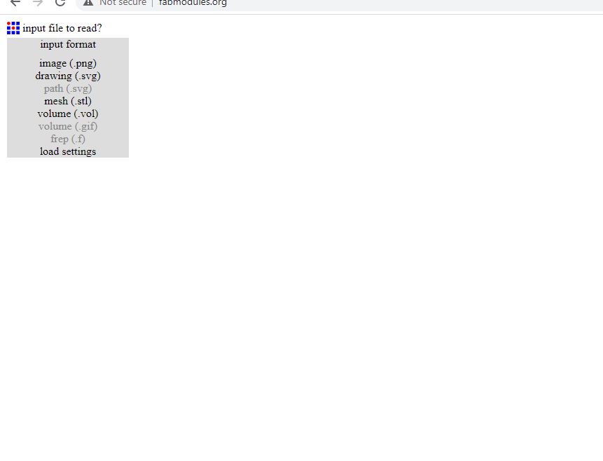
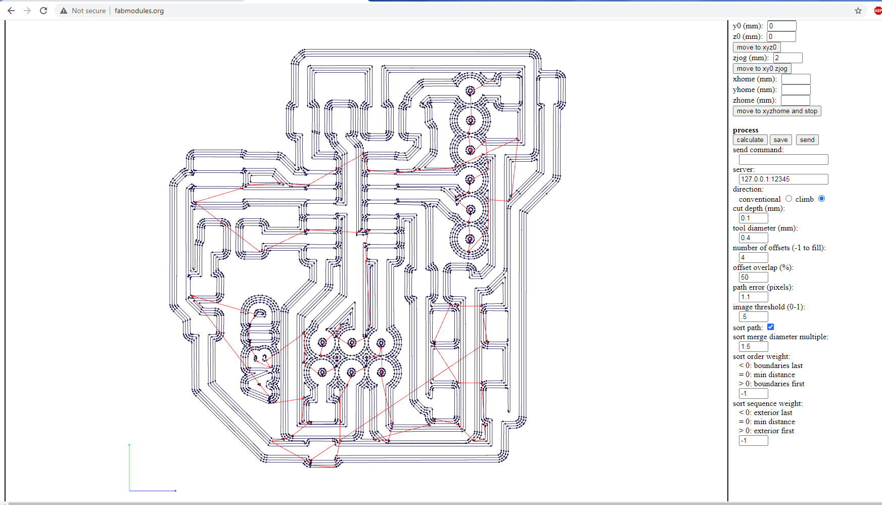
Rml file
Milling
After genarting the .rml file from the png through "mods.cba.mit.edu" . Now give it to the SRM 20 Milling Machine as we have learned how to operate the milling machine in the 5th week. And use the (1/64) bit for the traces and (1/32) for the drill and border as previously done.
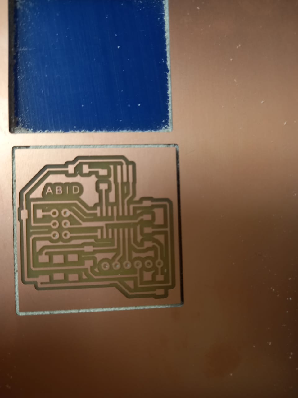
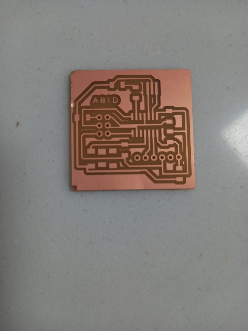
fig : Screen shot of PCB after Milling.
After checking the traces I found that the two pins are connected so I disconnect by them and the remaining circuit was ok.
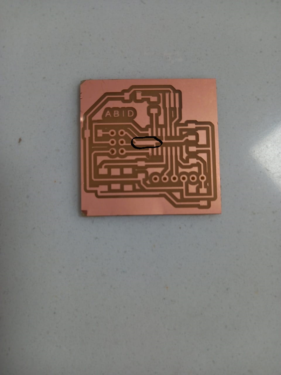
shortcircuit of two lines
Soldering
As the machine has milled the board and is ready to soldering.
I start with listing down the components used in the circuit along with the quantity and paste the component accordingly in the
page for easy recognition of components.
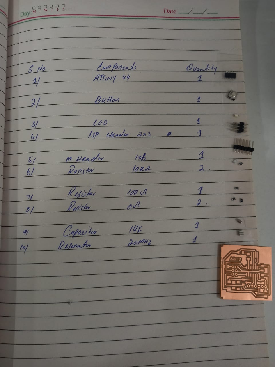
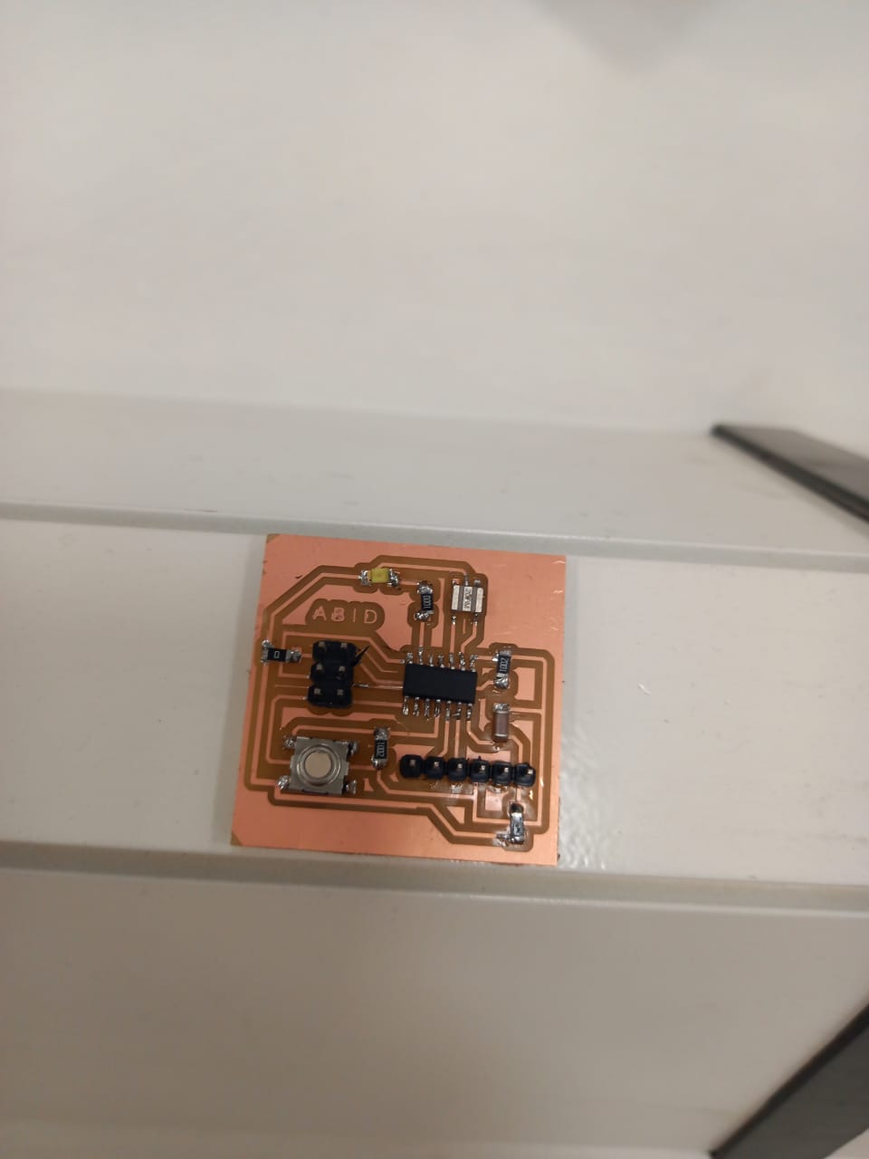
Bill of Material and after soldering board
Burn Boot Loading
After soldering first I burn the boot loader in the board.
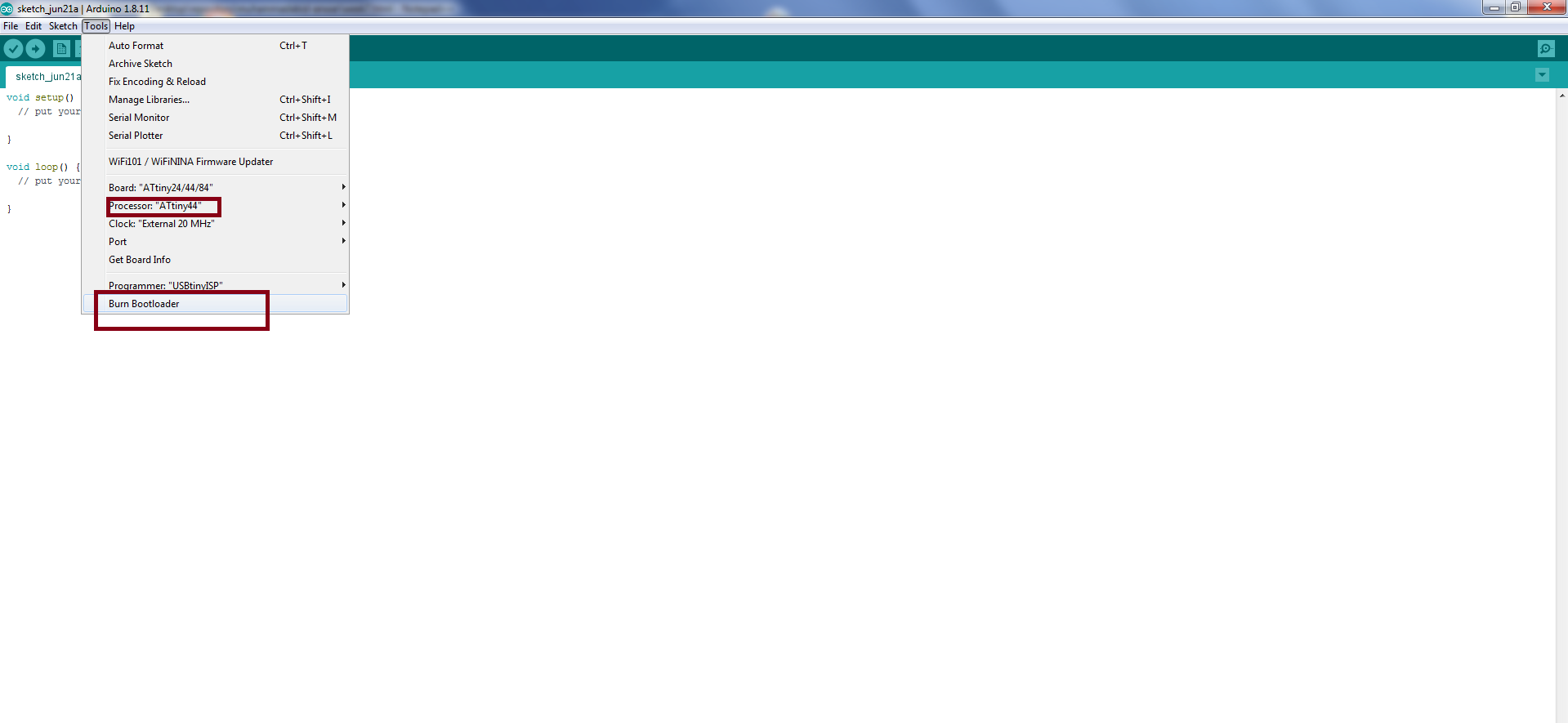
burn bot loading
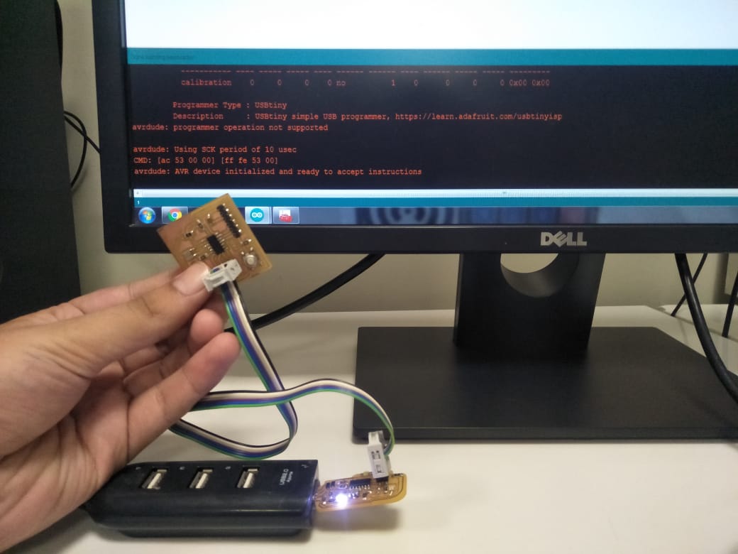
Programing and Testing
As we soldered the board and now is time to program the board. I use my week 5 development board and cable to burn the code
in the hello-world board. Use Arduino IDE to upload code, first I burn the code,then I upload the blink code in hello-world board.
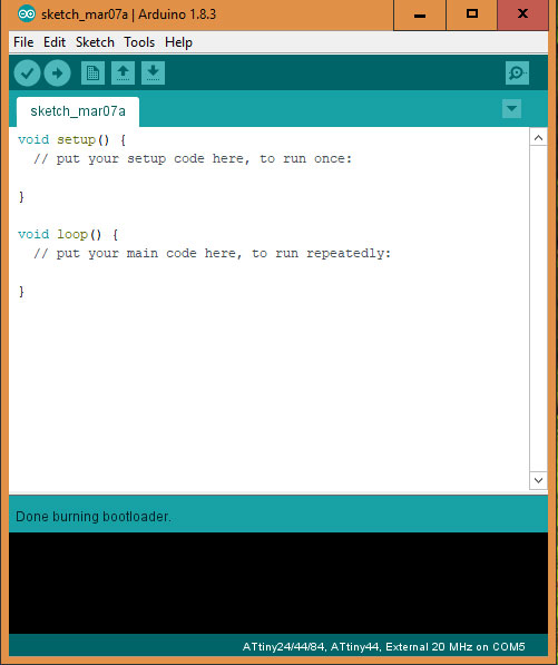
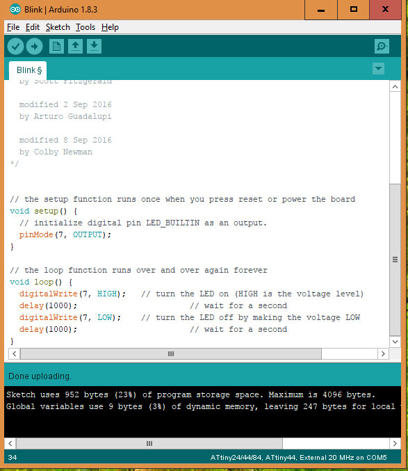
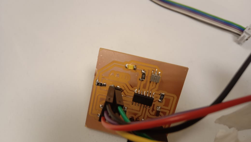
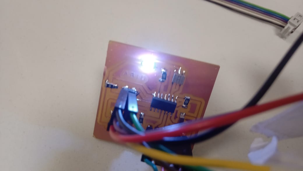
fig : screen shot of the cicuit board while programing and Led blinking.