Group Assignment:
Probe an input device's analog levels and digital signals.
OSCILLOSCOPE:
While working with electronics, for debugging and testing behavior, we need to understand the circuits on signal level,
which multimeters fails to do. In this case Oscilloscopes comes into picture. A digital oscilloscope measures the signal,
and then converts that measurement into a digital format using an ADC converter, after which the data measured is depicted as a
digital waveform representation. From this representation various paramters can be evaluated.
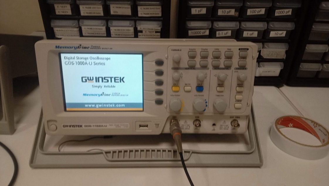
In our lab this oscilloscope is available we can observe the output of digital or Analog signal using it.
SIGNAL WAVE FORM BEHAVIOUR
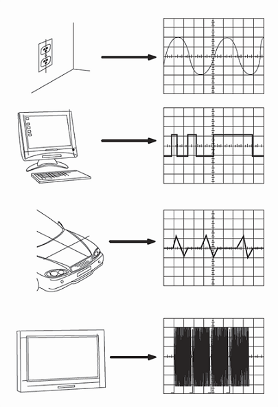
Electrical stations, computers, motorcycles, and televisions are examples of typical waveform sources.
SPECIFICATION OF GOS-1152A-U
*150 MHz Bandwidth.
*1 GSa/s Real-Time Sample Rates Maximum, 25GSa/s Equivalent-Time.
.
.
*2 Mega Point Record Length.
*2mV-10V Vertical Scale.
*1ns-50s Horizontal Range.
*Up to 27 Automatic Measurements.
*5.7" TFT LCD Display.
DIGITAL SIGNAL WAVE FORM
We initially evaluated the IR sensor on an Arduino UNO by connecting the probes to the IR output pin, which displays a frequency in the form of waveform on oscilloscope.
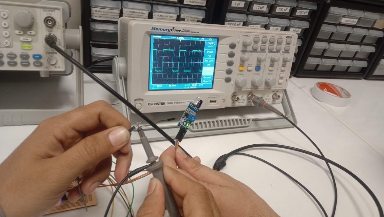
Here, we are observing the output of the IR sensor. it generates the square wave.
ANALOG SIGNAL WAVE FORM
In order to observe analog signals, We attached the motor's terminals to the probes on the Digital OSCILLOSCOPE and manually rotated the motor shaft.
The motor generates an Output signal on the oscilloscope.
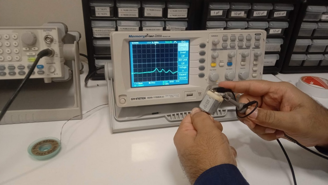
Here, this wave form shows the analog signal..
Individual Assignments:
Measure something: add a sensor to a microcontroller board
that you have designed and read it.
The first thing in this week was to decide what sensors I need to use. There are a lot of sensor available in our
lab that we can use in this week.But as I have to use the IR (Infea red) sensor in my final project So I decide to use the IR Sensor.
IR Sensor
An infrared (IR) sensor is an electronic device that measures and detects infrared radiation in its surrounding environment.
Infrared technology addresses a wide variety of wireless applications. The main areas are sensing and remote controls. In the electromagnetic spectrum, the infrared portion is divided into three regions:
near infrared region, mid infrared region and far infrared region.
The wavelengths of these regions and their applications are shown below.
Near infrared region — 700 nm to 1400 nm — IR sensors, fiber optic
Mid infrared region — 1400 nm to 3000 nm — Heat sensing
Far infrared region — 3000 nm to 1 mm — Thermal imaging
The frequency range of infrared is higher than microwave and lesser than visible light.
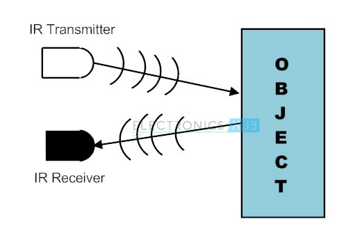
Fig:showing the Transmitter and receiver of IR Sensor .
The second thing is that to design and board for the circuit I decide to design the board that I can use it in my final project. After calculation
the number of pins required for input and output of my project I decide to sketch the satsha kit.
A Satsha kit uses mostly the same components as we use in arduino microcontroller , the ATmega 328p.From this data sheet, I realize that
what possible inputs and outputs I can get from this .
Sor for my easy and advantage for desire pins , As mentioned in the Satsha Kit
web page it uses 16Mhz instead of 8Mhz, also
a crystal instead of resonator,So by Geeting help from this I start to design the satsha kit and and try to modify the pins.As according to my
requirment.
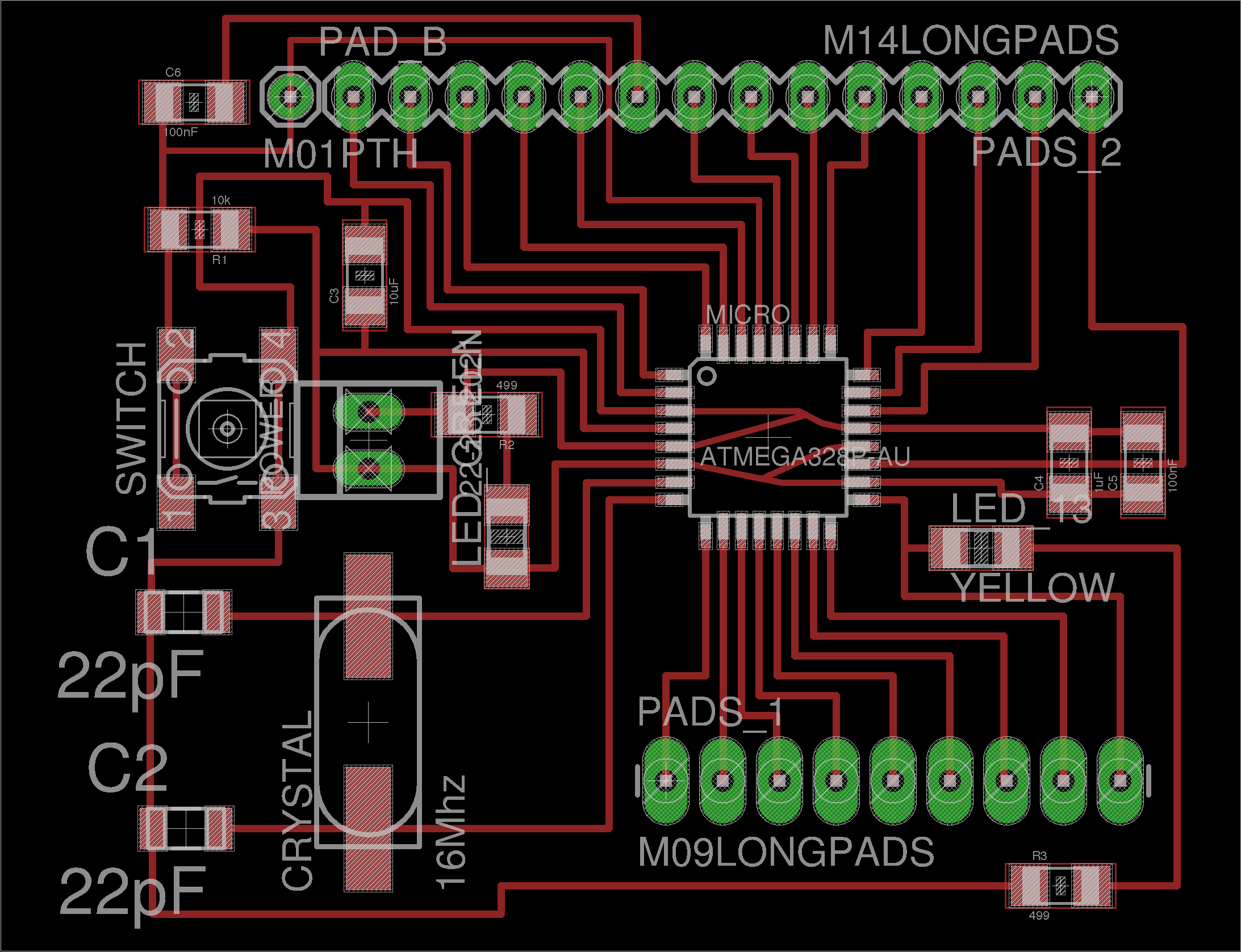
Fig:showing the pic of the satsha kit use as refrence and get help .
After that I start to add components in the Sketc in Eagle software
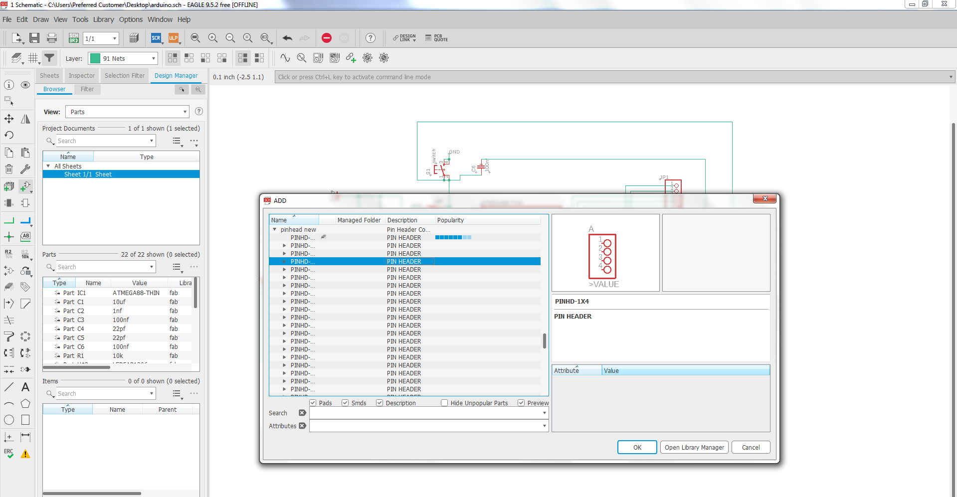
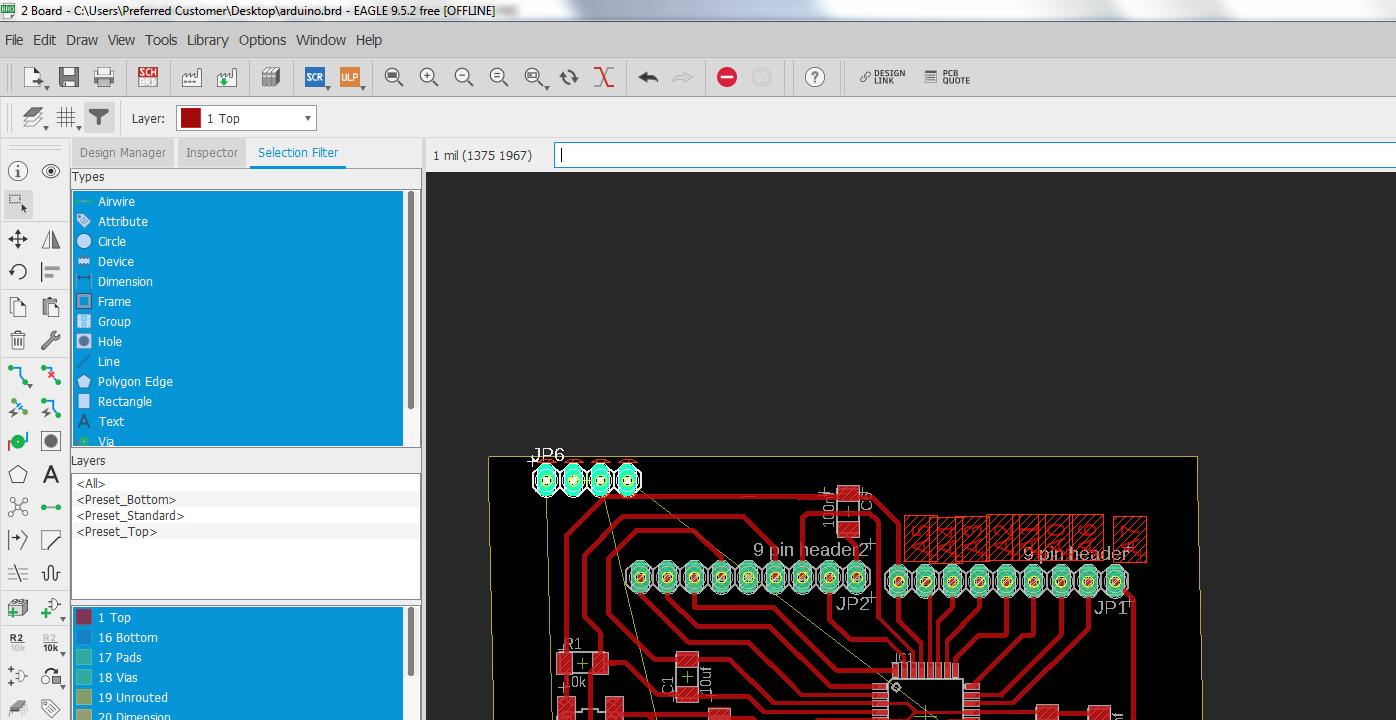
Fig:showing adding the pins and the componets .
After Adding the required components the final daigram is as under.
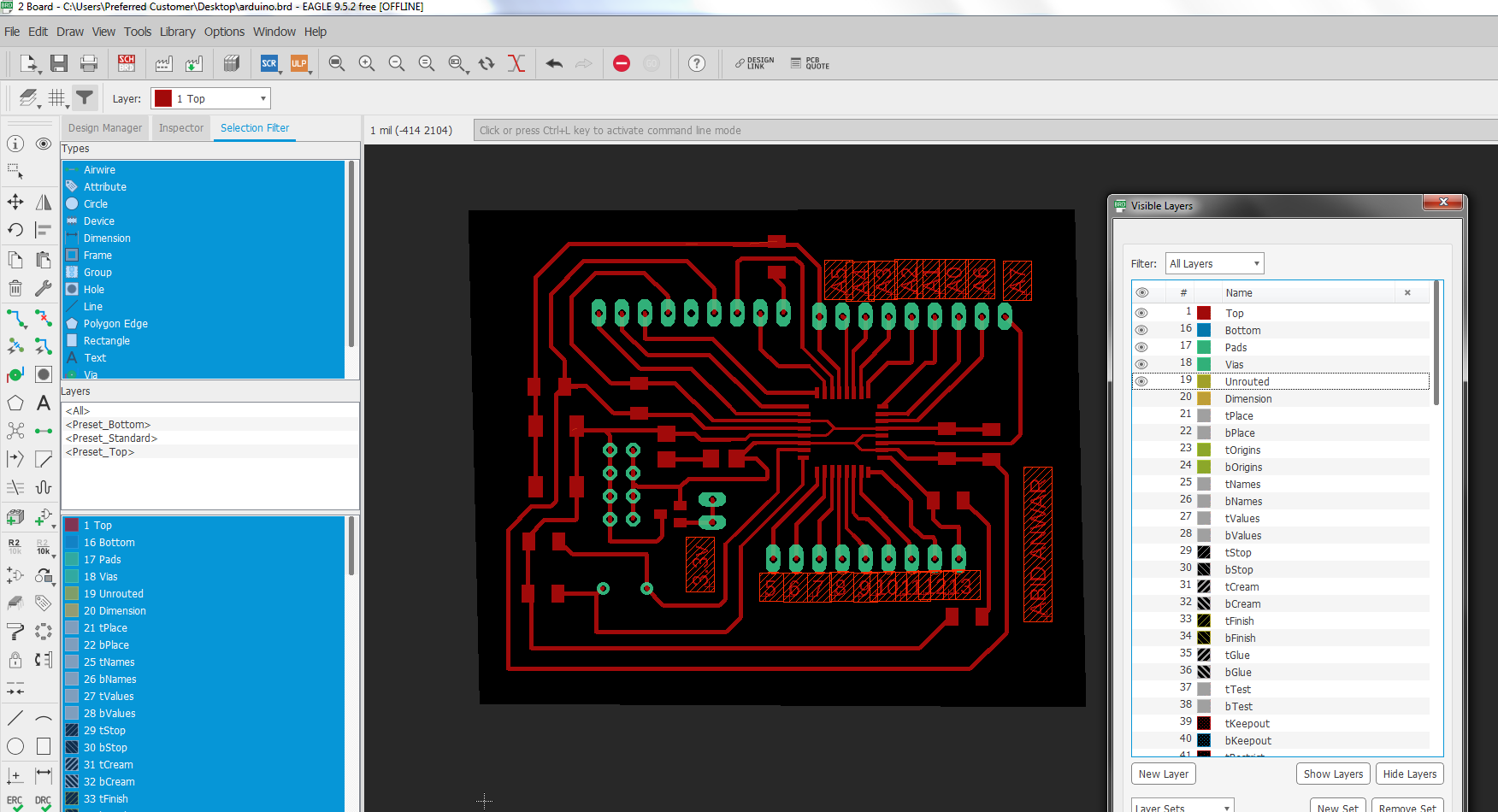
Fig:showing Screen shot of final design .
Once the design is clear and ready I save the design in png format and from that png format picture. By opening the paint application I design the traces , holes and the border.
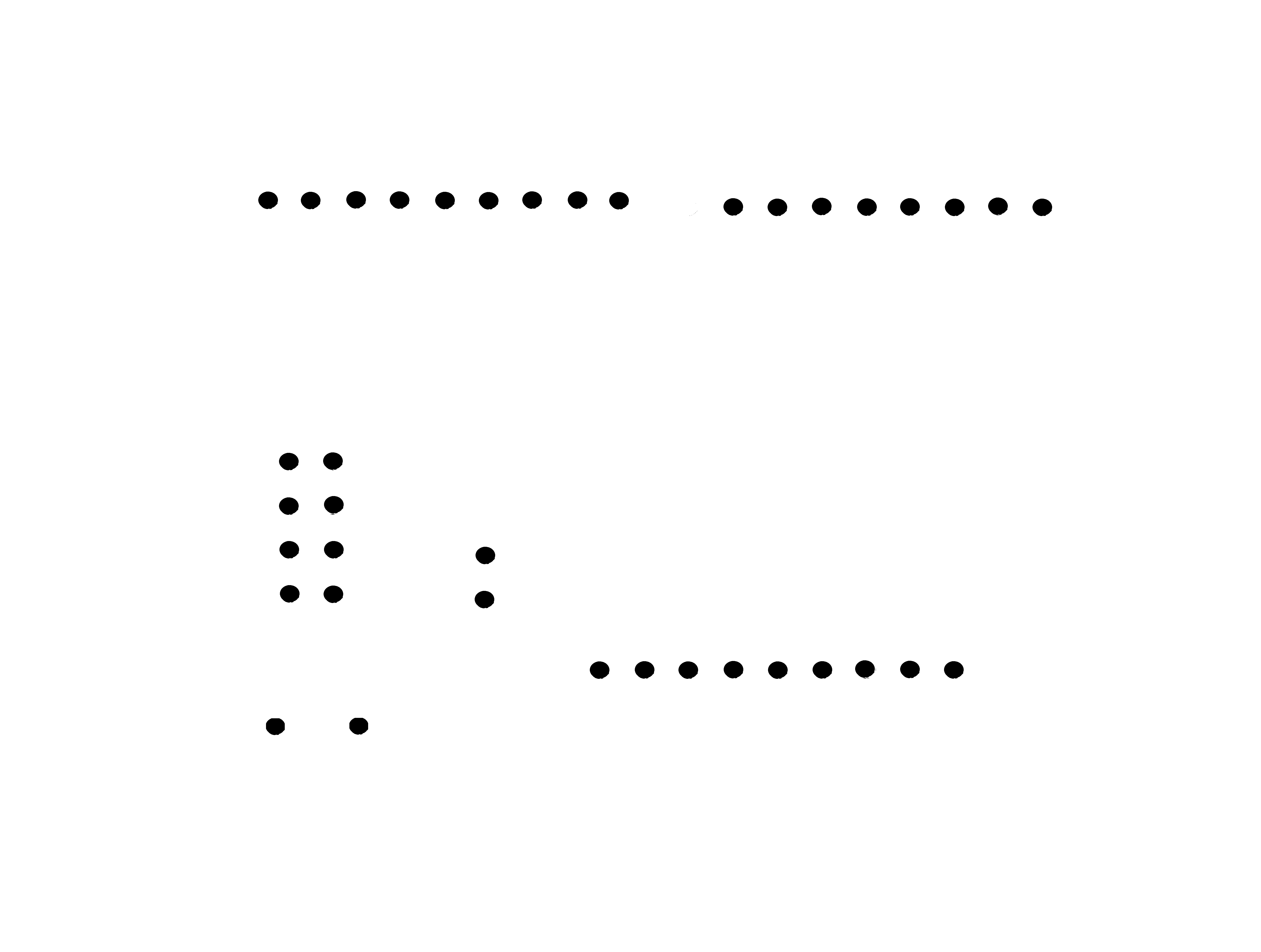

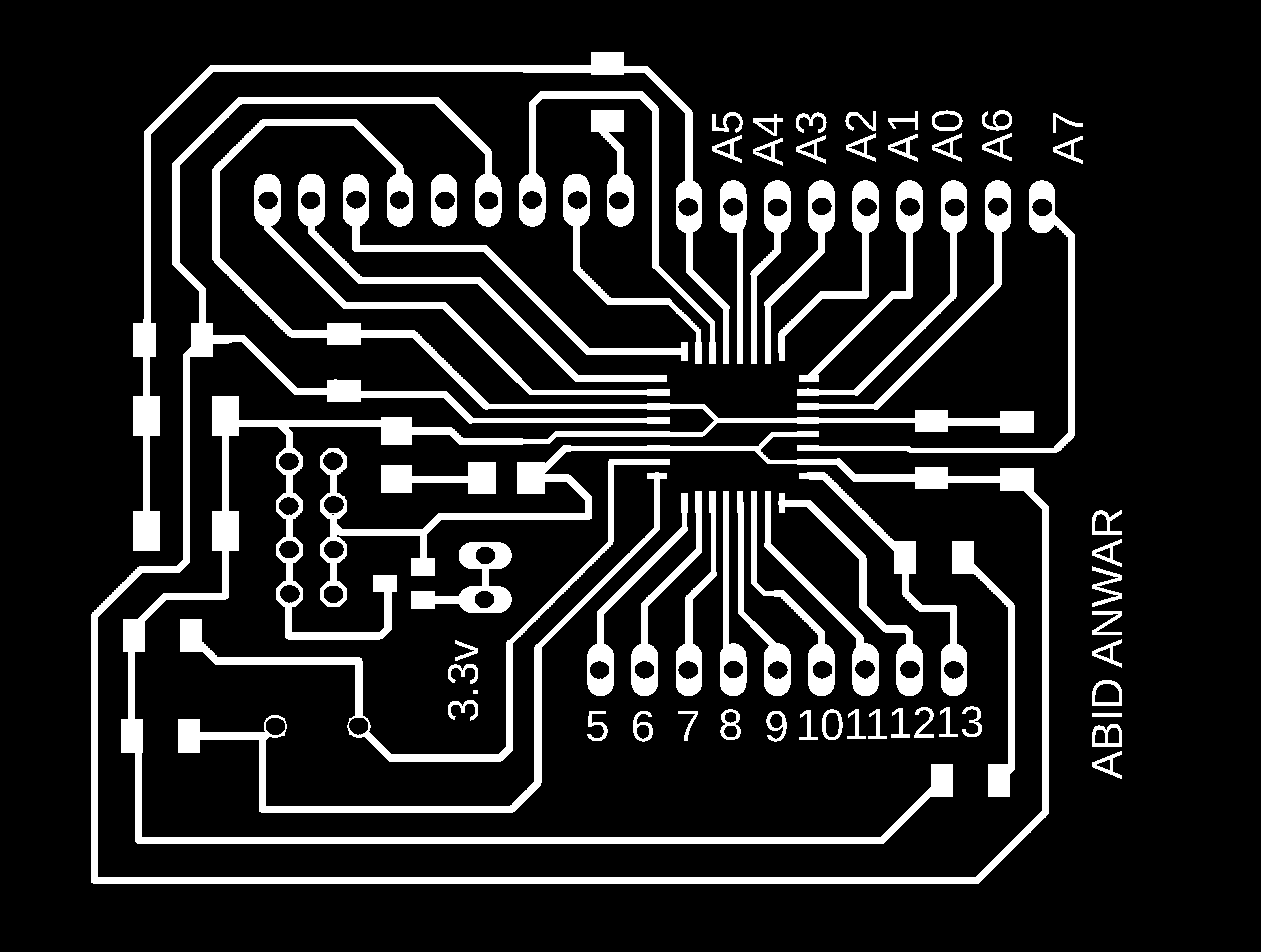
Fig:showing the drill,border and traces .
I use the above png file of the drill,border and traces, to generate the rml file for each.

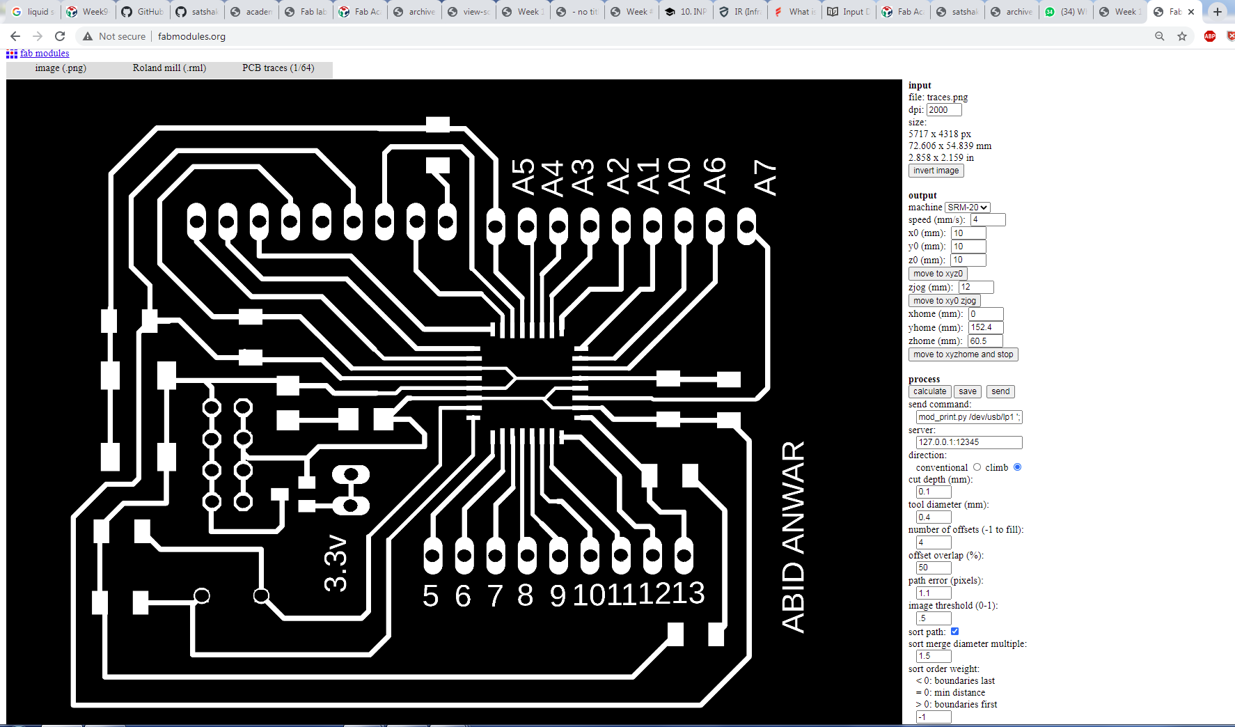
Fig:showing generating rml code for the traces .
Now the working on the SRM 20 Machine start I give the rml code to the srm 20.To mill the board accordingly.For this irst i set x, y and z axis for appropriate working.
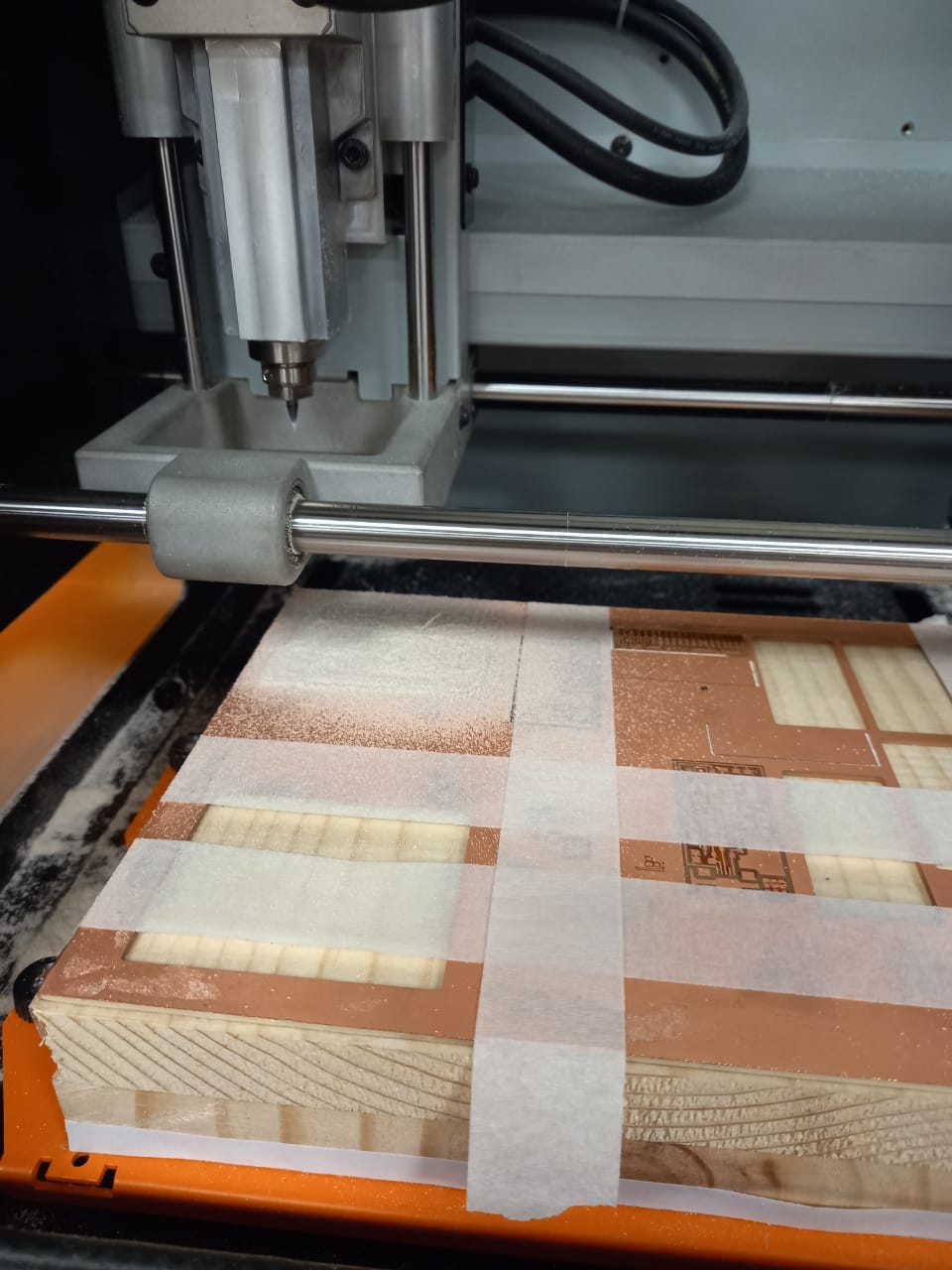
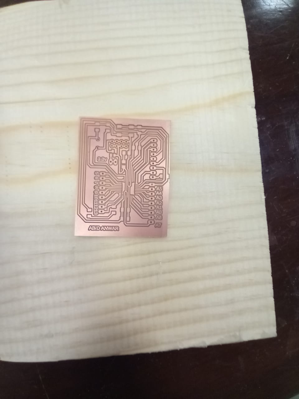
Fig:showing during and after milling of the board.
When milling is done I get the require components from lab inventory and start to solder the components.
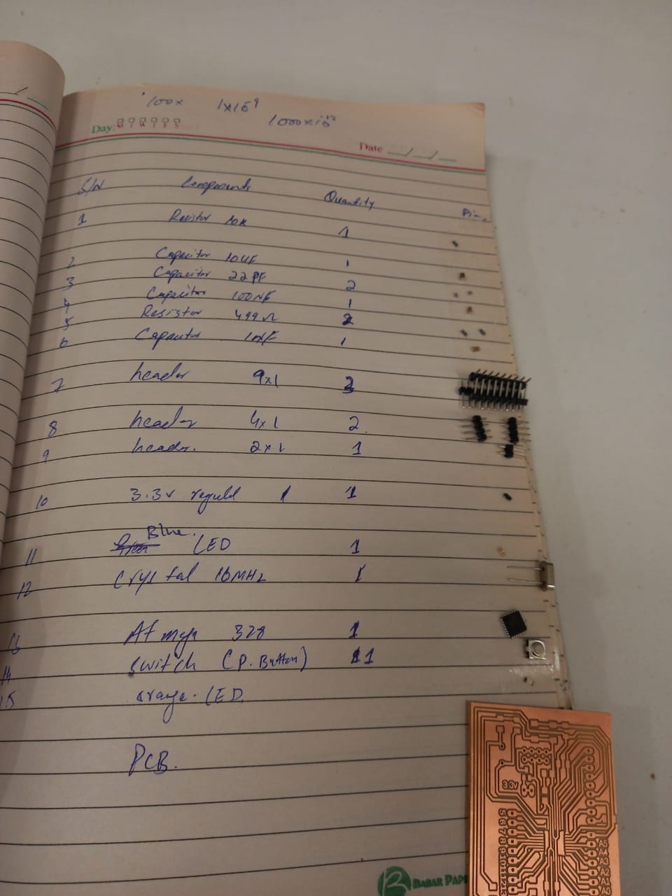
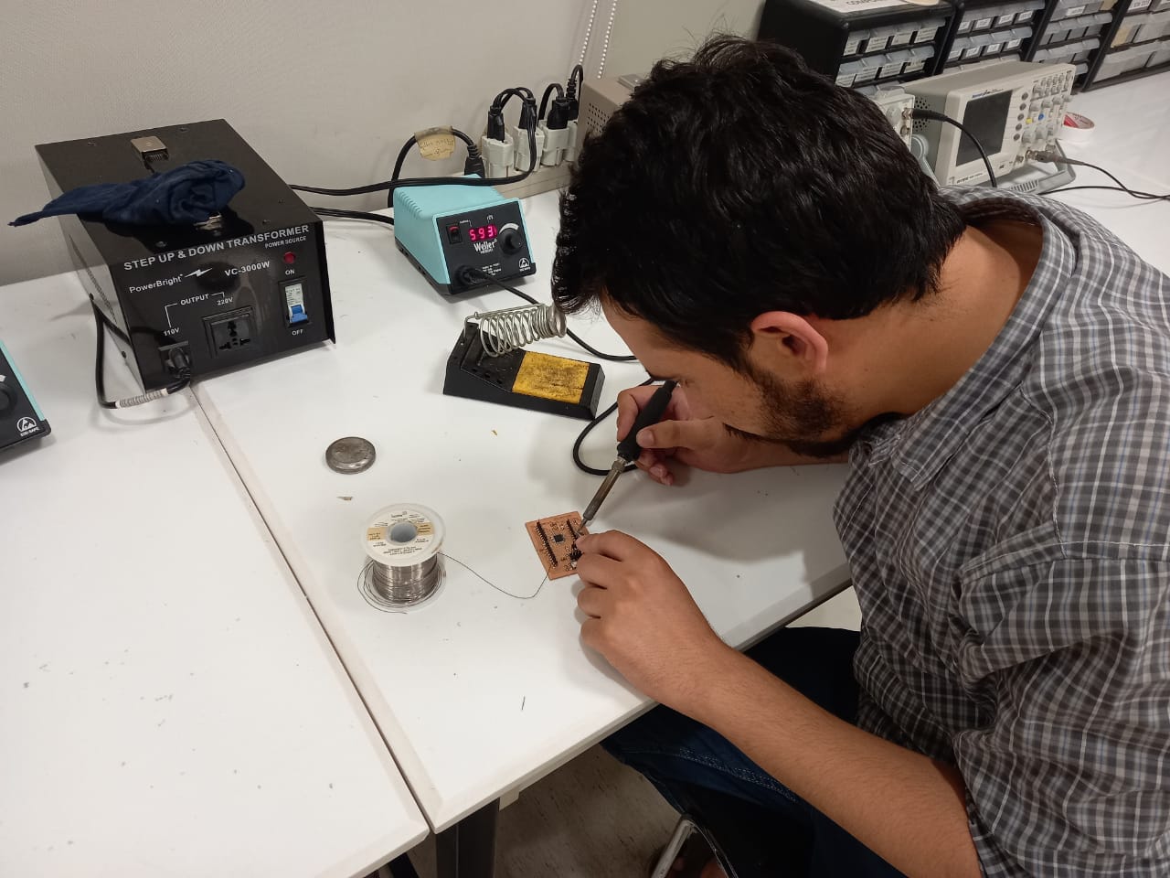
Fig:showing soldering the components.
After Soldering the final board look as :

Fig:showing picture of the board after soldering.
Now the programming work is remaining so for this I open the arduino and select the pin for output and input for the ir sensor.
The code for the programming is as follow;
void setup()
{
pinMode(5,OUTPUT);
pinMode(6,INPUT);
Serial.begin(9600);
}
void loop()
{
if (digitalRead(6)== LOW)
{
digitalWrite(5,HIGH);
delay(10);
}
else
{
digitalWrite(5,LOW);
delay(10);
}
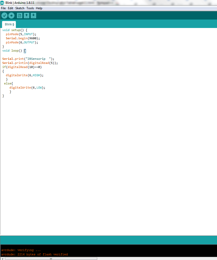
Fig:showing the program uploading done.
Description of CODE
The basic concept and gist of the code is that whenever the IR sensor detect any obstacle or any object within its specified region then it will detect it and the Controller work on the basis of that.
The description of code is that pin 5 is select as the Output pin , the pin 6 is select as the input pin , mean that the IR sensor is connected to the pin 6, and the output device will be connected to the
pin 5,
Whenever there is no obstacle or any object with in specified region the pin 6 will observe as receiving no any signal so according to the code the output pin 5 will be high.
In the same way when there come any obstacle with in the region the pin 6 will observe it as a signal and according to the code the output pin 5 will be low. As shown in the video as: