Week 08: Embedded programming
For this assignment I will use a board that I call MidTiny, it is an ATtiny board with all of its pins exposed and it also has an integrated button and LED.
The ATtiny1614 is a microcontroller featuring the 8-bit AVR® processor with hardware multiplier, running at up to 20 MHz and with 16 KB Flash, 2 KB SRAM and 128B of EEPROM in a 14-pin package.
Because the ATtiny1614 has an AVR processor it can be programmed using the standard AVR tools, but it is also possible to program it as if it were an Arduino, thanks to Spence Konde and the "megaTinyCore" library which is an Arduino Core for the tinyAVR 0-series and 1-series chips.
The megaTinyCore library relates the pins of the microcontroller with a pin number just like an Arduino, as this facilitates the programming process and frees the programmer from thinking if the pin corresponds to the PORTA or PORTB etc.
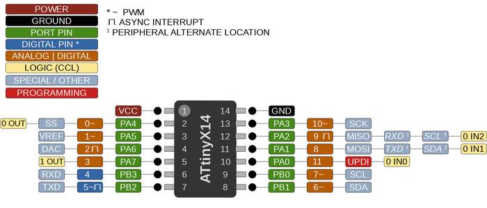
The following image illustrates the ATtiny1614 microcontroller, the pins of the microcontroller, its equivalent in Arduino and the functionalities or actions associated with each pin.
The datasheet of the ATtiny1614 microcontroller can be found at this link
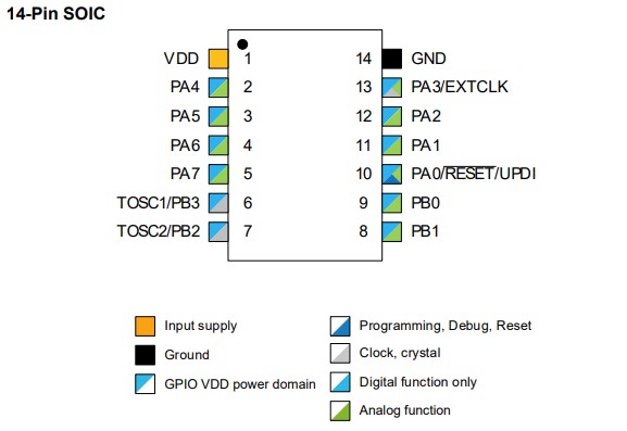
From the datasheet an important image to program the pins of the microcontroller is the following one showing the pins to be programmed.
A very useful link is this which contains information on how to program AVR architecture microcontrollers in C.
The following Arduino program blinks the LED that is connected to the PA5 pin of the microcontroller, that pin corresponds to pin 1 in the megaTinyCore library.
                           /*
                           * Blink program
                           * An arduino program that blink the led
                           * connected to pin 1/PA5 of the MidTiny board (ATtiny1614).
                           *
                           * Author: Harley Lara
                           * Create: 03 May 2021
                           * License: (CC BY-SA 4.0) Attribution-ShareAlike 4.0 International
                           *
                           * This work may be reproduced, modified, distributed,
                           * performed, and displayed for any purpose, but must
                           * acknowledge this project. Copyright is retained and
                           * must be preserved. The work is provided as is; no
                           * warranty is provided, and users accept all liability.
                           *
                           */

                           #define LED 1 // Define LED pin
                           #define DELAY 500 // Define waiting time

                           void setup() {
                               pinMode(LED, OUTPUT); // Define the led port as output.
                           }

                           void loop() {
                               digitalWrite(LED, HIGH); // LED ON
                               delay(DELAY); // Wait half a second
                               digitalWrite(LED, LOW); //LED OFF
                               delay(DELAY); // Wait half a second
                           }
The code is quite simple, it starts by defining LED 1 which corresponds to the pin to which the pcb LED is connected, it also defines DELAY 500, which corresponds to 500ms of blinking.
In the setup() section we define with pinMode() the LED port as output.
The loop() section is the function that is repeated indefinitely and contains the code that turns the LED on and off. To turn on the LED the pin must be high, that is achieved with the digitalWrite() function, that function is given as argument the pin we want to write and the value we want to write.
The following instruction simply waits 500ms and then passes to the next one.
It is also possible to program the ATtiny microcontrollers using C, in this section I made the same program above with its C equivalent.
                           #define F_CPU 3333333
                           #include <avr/io.h>
                           #include <util/delay.h>

                           #define LED PIN5_bm // Define LED pin
                           #define DELAY 500 // Define waiting time

                           int main(){

                               PORTA.DIR |= LED; // Define the led port as output

                               while(true){
                                   PORTA.OUT |= LED; // LED ON
                                   _delay_ms(DELAY); // Wait half a second

                                   PORTA.OUT &= ~LED; //LED OFF
                                   _delay_ms(DELAY); // Wait half a second
                               }

                               return 0;
                           }
To use C functions to program the board it is necessary to include the avr/io.h library that contains all the definitions to work with I/O in AVR processors. The next library that needs to be added is util/delay.h which allows to use delay functions, but for the delay time to be interpreted correctly it is necessary to define the clock speed, this is achieved with #define F_CU 3333333 this number represents the clock speed divided by 6.
As in the arduino code the pin to which the LED is connected is defined with the difference that in the code pin 1 is used but this time it is necessary to use the microcontroller pin, which corresponds to PIN 5 of the PORTA.
In C there is a main function called main() which is the entry point of the program.
The next instruction defines the LED pin as the output.
For the program to continue indefinitely and not terminate after executing all the instructions it is necessary to add the while(true) function that keeps the loop executing.
To activate the LED it is necessary to define the output port to which the pin to be activated corresponds.
The delay function simply waits 500ms.
The next instruction that makes use of "&= ~" turn off the LED.
The above C code works very well but it can be a bit more efficient if you use an assignment that reverses the state of the LED, this works like a state toggle. Using that we can reduce the task of blinking the LED to just 2 lines of code.
                        /*
                        * Blink program
                        * An C program that blink the led
                        * connected to PA5 of the MidTiny board (ATtiny1614).
                        *
                        * Author: Harley Lara
                        * Create: 03 May 2021
                        * License: (CC BY-SA 4.0) Attribution-ShareAlike 4.0 International
                        *
                        * This work may be reproduced, modified, distributed,
                        * performed, and displayed for any purpose, but must
                        * acknowledge this project. Copyright is retained and
                        * must be preserved. The work is provided as is; no
                        * warranty is provided, and users accept all liability.
                        *
                        */

                        #define F_CPU 3333333
                        #include <avr/io.h>
                        #include <util/delay.h>

                        #define LED PIN5_bm // Define LED pin
                        #define DELAY 500 // Define waiting time

                        int main(){

                            PORTA.DIR |= LED; // Define the led port as output

                            while(true){
                            PORTA.OUT ^= LED; // LED toggle ON/OFF
                            _delay_ms(DELAY); // Wait half a second
                            }

                            return 0;
                        }
The following C program activates the LED when the button connected to pin PA4 (equivalent to pin 0 in arduino) is pressed.
                        /*
                        * Button pressed LED ON
                        * A C program that activates the LED connected
                        * to the PA5 pin when pressing the button
                        * connected to the PA4 pin of the MidTiny board (Base ATtiny1614).
                        *
                        * Author: Harley Lara
                        * Create: 03 May 2021
                        * License: (CC BY-SA 4.0) Attribution-ShareAlike 4.0 International
                        *
                        * This work may be reproduced, modified, distributed,
                        * performed, and displayed for any purpose, but must
                        * acknowledge this project. Copyright is retained and
                        * must be preserved. The work is provided as is; no
                        * warranty is provided, and users accept all liability.
                        */

                        #define F_CPU 3333333
                        #include <avr/io.h>
                        #include <util/delay.h>

                        #define LED PIN5_bm // Define LED pin
                        #define BUTTON PIN4_bm // Define BUTTON pin

                        int main() {

                            PORTA.DIR |= LED; // Define the LED port as output
                            PORTA.OUT &= ~LED; // Set the initial state of the LED OFF

                            PORTA.DIR &= ~BUTTON; // Define the button port as input
                            PORTA.PIN4CTRL = 0; // Don't use the internal pullup resistor

                            while (true) {
                            _delay_ms(10); // Wait
                            if (PORTA.IN & BUTTON) // If the button is pressed
                            {
                                PORTA.OUT ^= LED; // LED toggle ON/OFF
                            } else {
                                PORTA.OUT &= ~LED; // If the button is not pressed set LED OFF
                            }
                            }

                            return 0;
                        }
The following code implements debounce to avoid rapid state changes and Latching to maintain the previous state.
                        /*
                     Blink program
                     Latch and Debounce for the MidTiny board (ATtiny1614).

                     Author: Harley Lara
                     Create: 03 May 2021
                     License: (CC BY-SA 4.0) Attribution-ShareAlike 4.0 International

                     This work may be reproduced, modified, distributed,
                     performed, and displayed for any purpose, but must
                     acknowledge this project. Copyright is retained and
                     must be preserved. The work is provided as is; no
                     warranty is provided, and users accept all liability.

                     */

                     #define F_CPU 3333333
                     #include <avr/io.h>
                     #include <util/delay.h>

                     #define LED PIN5_bm // Define LED pin
                     #define BUTTON PIN4_bm // Define BUTTON pin

                     // saves the latest status
                     //    false: released
                     //    true: pressed
                     bool last = false;

                     int push_level = 0;
                     int release_level = 0;
                     int threshold = 50;

                     int main() {

                     PORTA.DIR |= LED; // Define the LED port as output
                     PORTA.OUT &= ~LED; // Set the initial state of the LED OFF

                     PORTA.DIR &= ~BUTTON; // Define the button port as input
                     PORTA.PIN4CTRL = 0; // Don't use the internal pullup resistor

                     while (true) {
                        if (PORTA.IN & BUTTON) {
                           push_level ++;
                           release_level = 0;
                           if (push_level > threshold ){
                           if (last == false){
                              PORTA.OUT ^= LED; // LED toggle ON/OFF
                              last = true;
                           }
                           push_level = 0;
                           }
                        }
                        else {
                           release_level ++;
                           push_level = 0;
                           if (release_level > threshold){
                           last = false;
                           release_level = 0;
                           }
                        }

                        _delay_ms(10);
                     }

                     return 0;
                     }
For this section I will compare the performance of 3 boards corresponding to the ATtiny1614, Arduino UNO (ATMEGA328P), Arduino DUE (AT91SAM3X8E).
The code used is the same for all tests.
                           /*
                           * pi.ino
                           * Neil Gershenfeld 12/20/20
                           * pi calculation benchmark
                           * pi = 3.14159265358979323846
                           */

                           #define NPTS 100000

                           float a,b,c,pi,dt,mflops;
                           unsigned long i,tstart,tend;

                           void setup() {
                              Serial.begin(115200);
                              }

                           void loop() {
                              tstart = millis();
                              a = 0.5;
                              b = 0.75;
                              c = 0.25;
                              pi = 0;
                              for (i = 1; i <= NPTS; ++i)
                                 pi += a/((i-b)*(i-c));
                              tend = millis();
                              dt = (tend-tstart)/1000.0;
                              mflops = NPTS*5.0/(dt*1e6);
                              Serial.print("NPTS = ");
                              Serial.print(NPTS);
                              Serial.print(" pi = ");
                              Serial.println(pi);
                              Serial.print("time = ");
                              Serial.print(dt);
                              Serial.print(" estimated MFlops = ");
                              Serial.println(mflops);
                           }
For the ATtiny1614 board the performance is as follows:
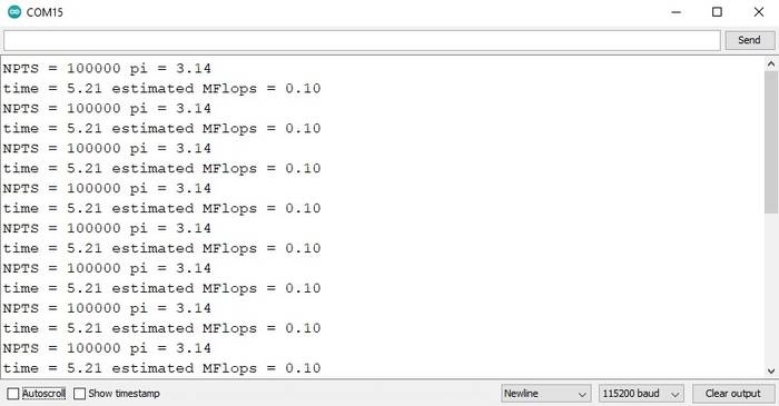
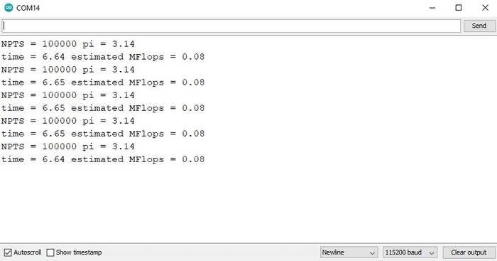
If we compare it with the previous generation (ATMEGA328P) we can see that the ATtiny1614 has an improvement in performance.
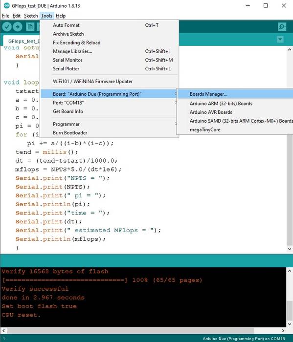
For the last test I used an Arduino DUE (AT91SAM3X8E) with a 32-bit ARM architecture. By default the library to program this board is not included in the Arduino IDE but it can be added very easily.
In the Arduino IDE go to the Tools -> Board: ... -> Boards Manager ... option.
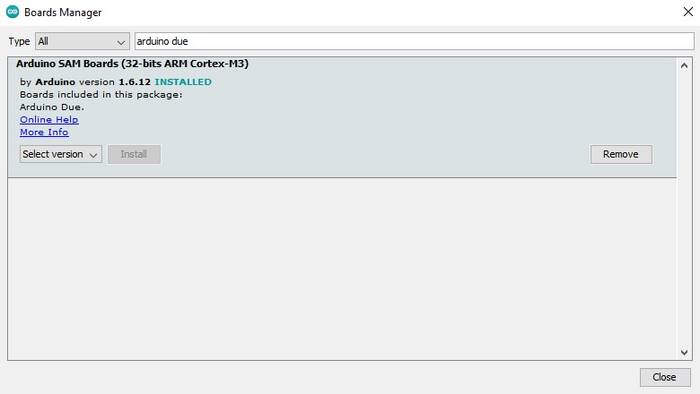
Then in the search bar type "Arduino DUE" and the following result will appear, just click on install and that's it.
The result for the Arduino DUE board is as follows.
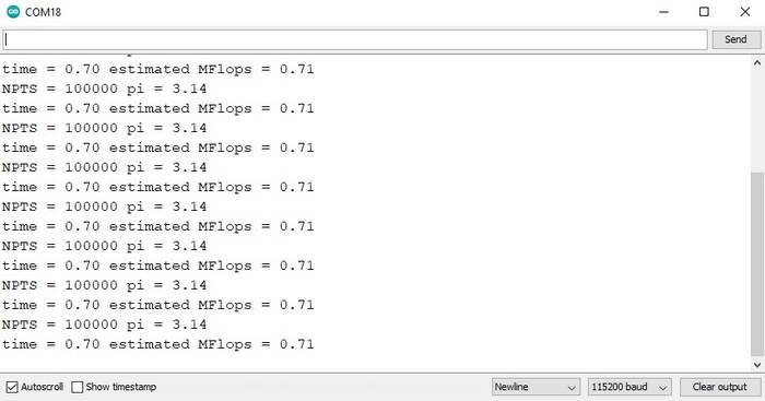
Indeed, it has better performance than the previous boards.
Link to the Group Assignment page
Blink C 01
Blink C 02
Button C
Latch and Debounce