Week 07: Computer-controlled machining
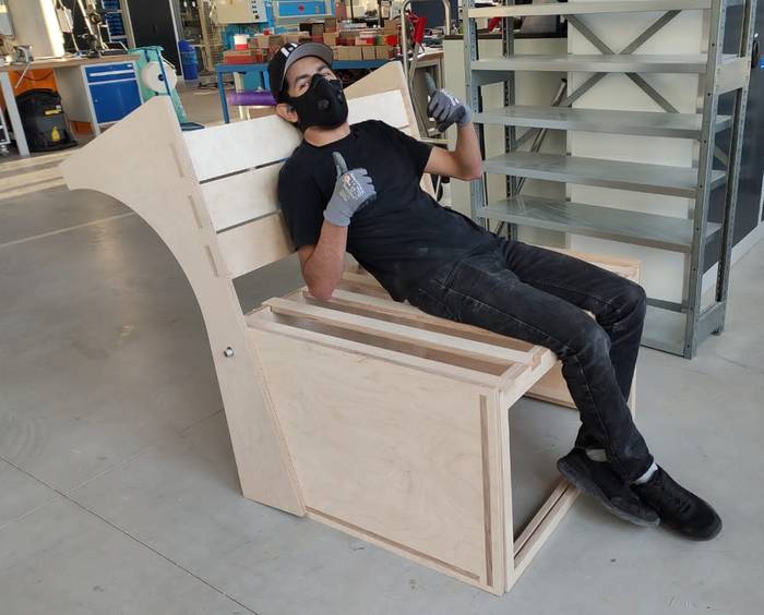
Every design process starts with an idea in mind, my idea was to create a piece of furniture that could be useful as a personal sofa but also function as a bed.
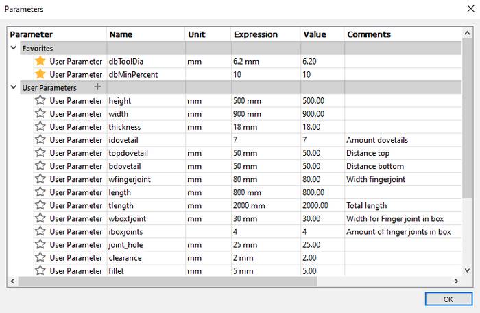
Since the design must be parametric I started by defining some parameters that I would use later in the design.
Because the final design is composed of a lot of pieces that interact with each other I decided to design in 3D since it is also possible to make a sketch of all the pieces in a two-dimensional plane and then assemble them, but for this design I will do it in 3D to take advantage of all the benefits of fusion and parametric design, also this way does not saturate the constrains sketch and it is much easier to make changes in the future.
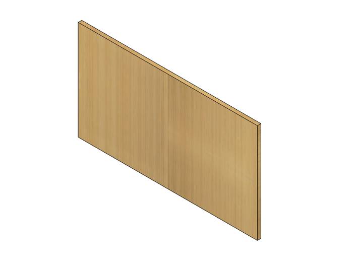
First I made a simple rectangle that corresponds to the front piece that in turn defines the width of the furniture.
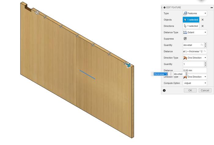
Next I designed a joint to support other pieces, for that I used the parameters, the parameter (thickness*2) to make a margin between the edge of the piece, and the parameter (bdovetail) that defines the width of the joint, the height of the joint is defined by the (thickness) parameter.
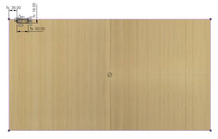
Of course the joints must go from one end of the part to the other, but doing all that in the sketch would create a difficult to edit in the future and like many constraints. To extend the joint from one end to the other I used the Rectangular Pattern tool in which I use the parameters (idovetail) to define the number of joints and calculate the distance between each joint as follows (-width + ( ( ( thickness * 2 ) + bdovetail ) + thickness * 2 ), that allows me to change any parameter automatically re-calculates the distance and the number of joints. I also want to mention that in the "Type" section in the Rectangular Pattern tool I used one of my favorite functions in Fusion 360 called "Features" which basically uses modifiers like Extrude, Resolve, Hole, Shell, Fillet or any other tool as input parameter, that means that previously I used Extrude to create the first joint then I can use that Extrude as input and create a Rectangular pattern based on that Extrude, so if the Extrude changes the rectangular pattern as well.
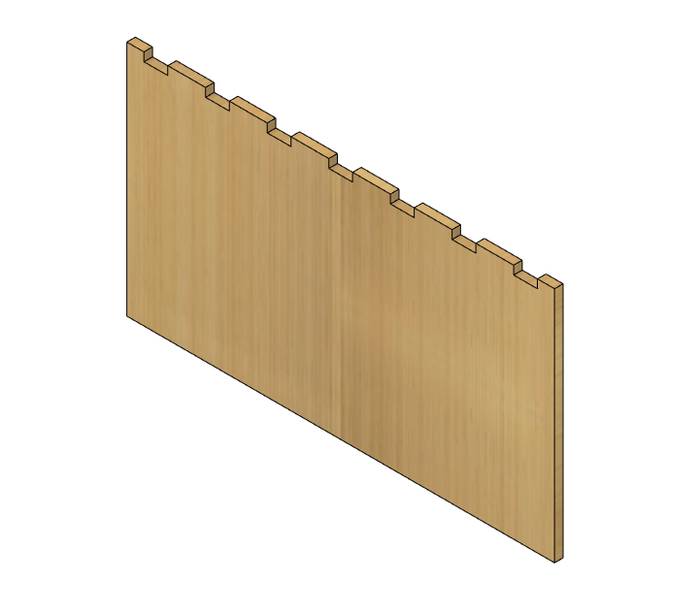
The result is as follows
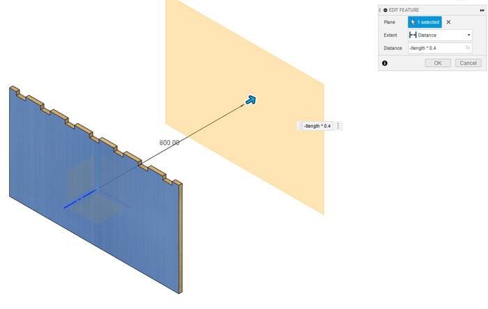
Now I need another piece exactly the same but located at a specific distance. To do that I use another of my favorite Fusion functions like Offset Plane, in which I can define a distance from a selected plane. The distance uses the parameter -(tlength * 0.4) which means that the distance is 2/5 of the total length of the piece of furniture.
But by creating the drawing we don't get the copy of the piece. The next thing is to create a sketch in the new plane created. but is it necessary to do all the above process to make the copy? the answer is of course NO you can use the Project function to project the shape of the previous piece to the new plane.
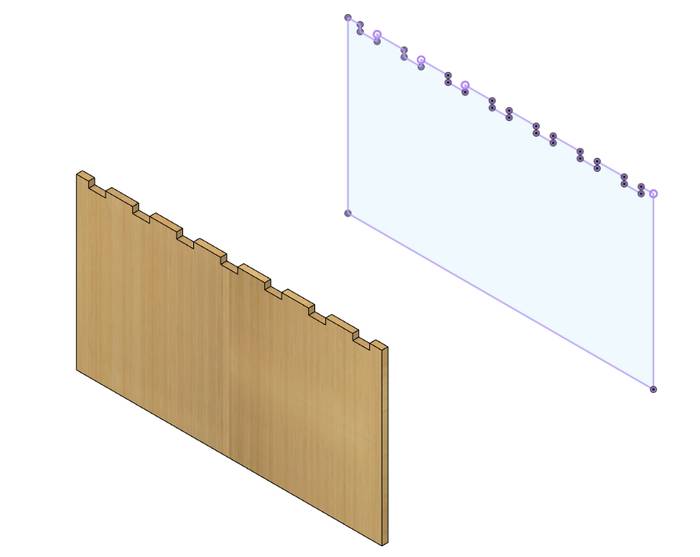
Then you just need to extrude the projection and you have an exact copy of the previous part. And why do it this way when Fusion has a Move/Copy function, is because this function although it is registered in the timeline does not save the input values as parameters, so if you edit any distance parameter is not updated, the shape of the body is changed but the position remains static.
From now on the process follows this same pattern of, design a simple parametric sketch with the least amount of constraints, apply Rectangular Pattern if necessary, and make use of Offset Plane and Project to create copies.
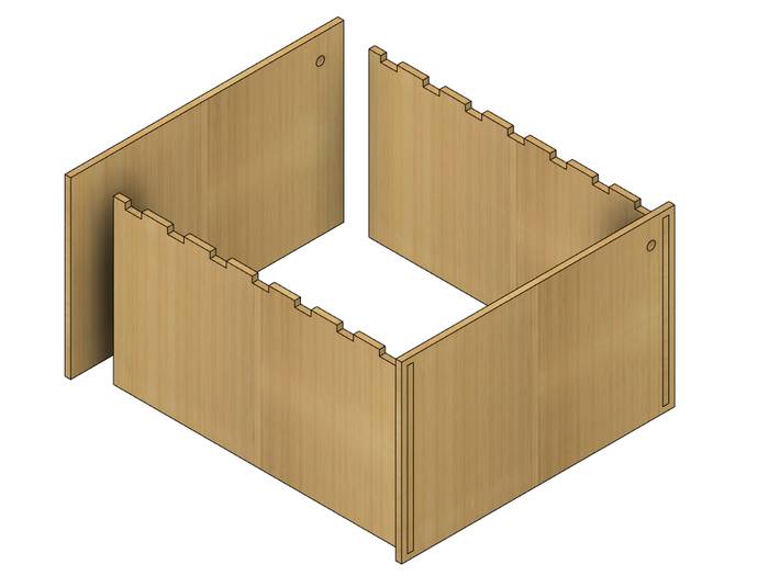
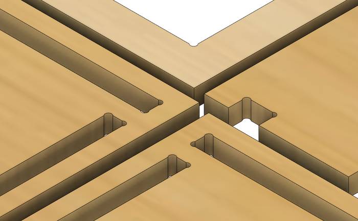
With the central part of the piece of furniture it may look like the components are assembled together when in fact they are just passing through each other and do not have the proper slots to place the other pieces.
This is easy to solve without the need to create a new sketch with more parameters and instructions to create the slots, plus the parametric characteristics are preserved. Since the parts are already in place and you only need to create the assembly slots that can be achieved with the Combine tool in which the Target Body is the part in which I want to make the slots, in Tool Bodies are the parts that I will use to make the slots, in the Operation option I select Cut and check the Keep Tools option to keep all the parts.
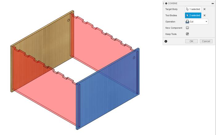
With the previous operation the assembly slots are created very easy and I feel completely parametric.
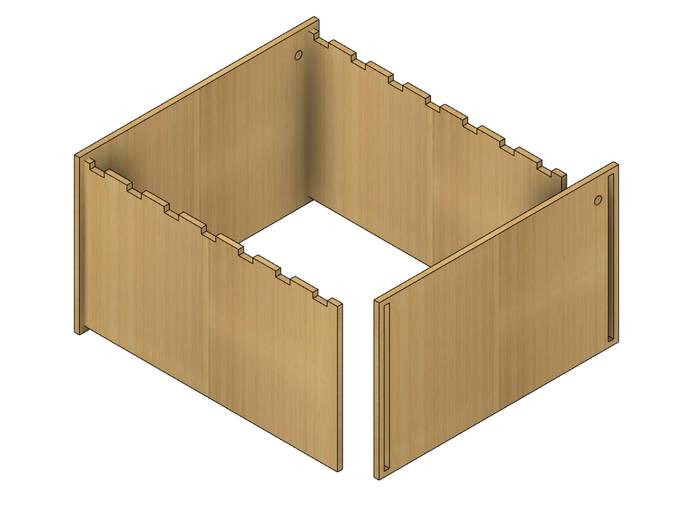
In summary with the Rectangular Pattern, Offset Plane, Project and Combine functions I make sure that everything remains parametric throughout the design process.
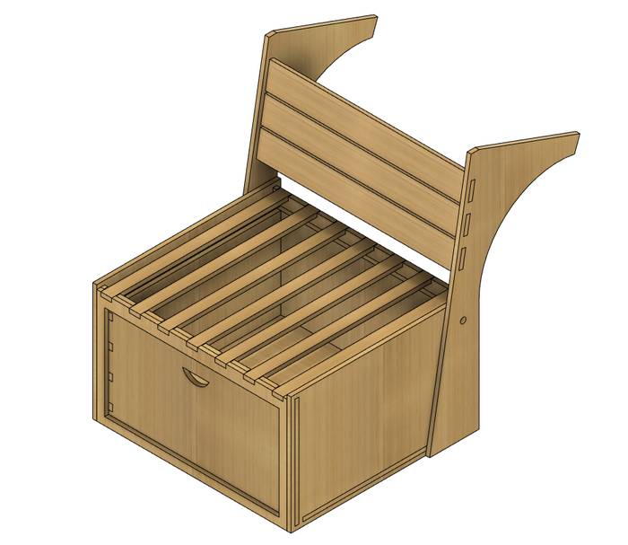
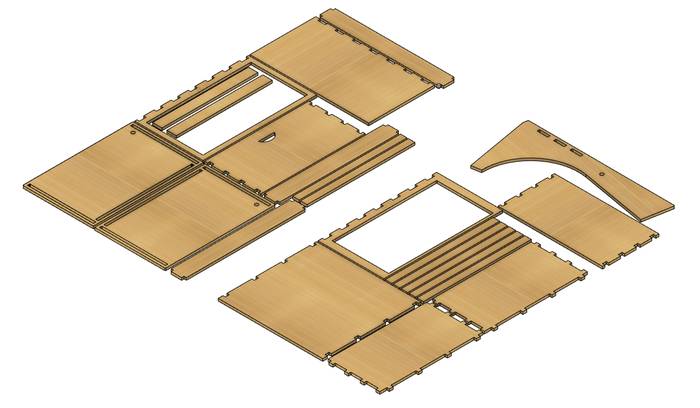
After a few hours of design applying the above methods the result is as follows.
The following is known as nesting, it consists of grouping all the parts in the best possible way to make use of the largest amount of available surface. In my case I did it manually grouping everything based on the sheet of wood available in the lab.
Now it is necessary to create the Dog bones, which were made thanks to the Add-Ins.
The CAM process starts by creating a Setup for the first hour of wood.
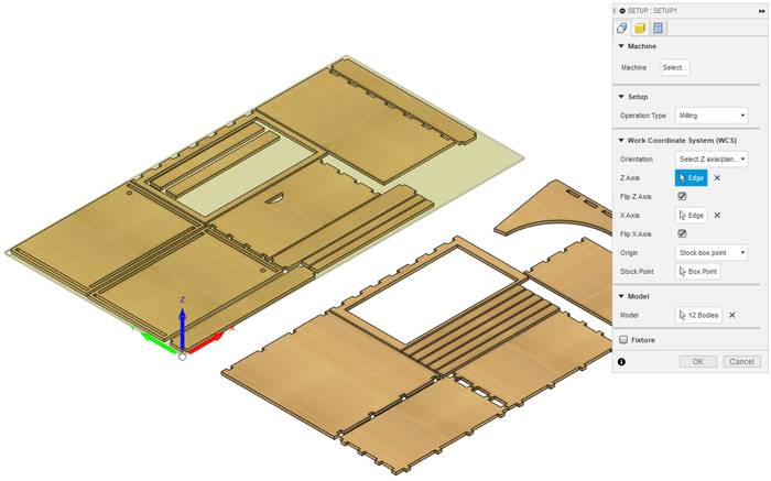
It is important to define the coordinate system so that it matches that of the physical machine.
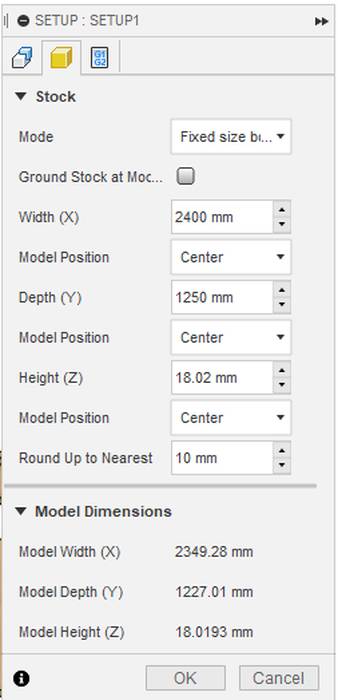
The next section is Stock where the dimensions of the available wood sheet are defined, in this case 2400x1250 mm and 18.02mm height.
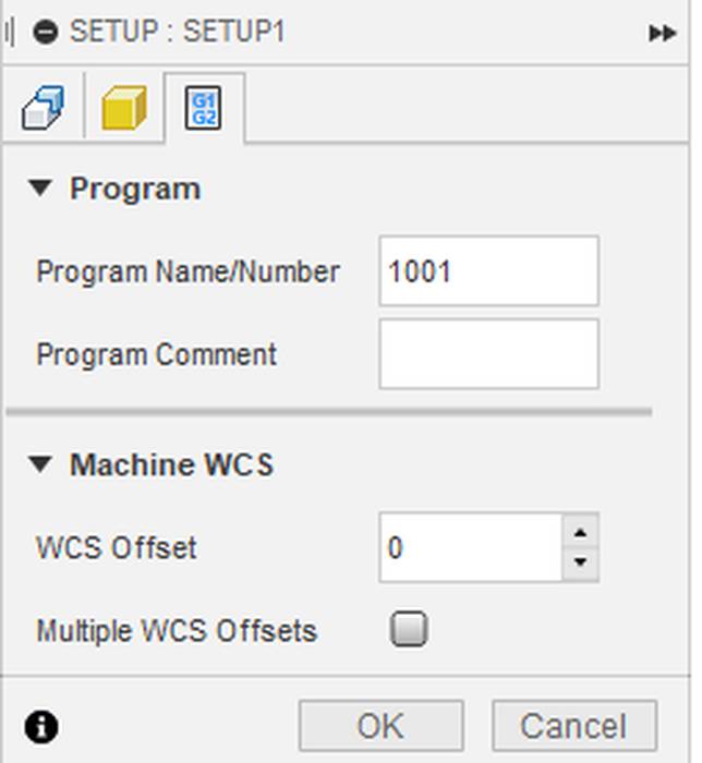
The Program tab remains the same
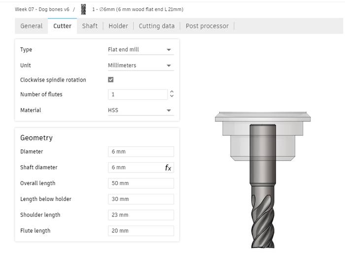
Before doing any work you need to define the dimensions and characteristics of the tool, in this case they are.
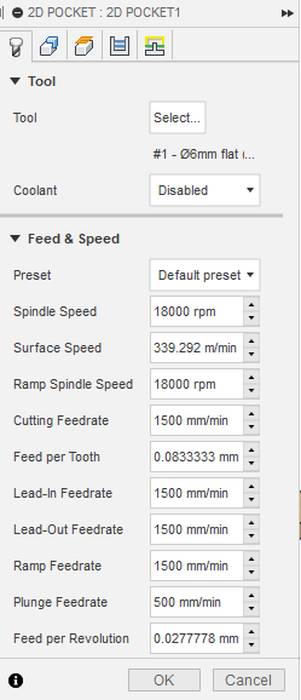
Now the first process to perform is Pocket.
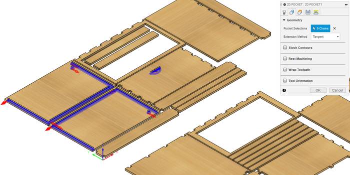
You have to mark the areas or geometries that you want to remove.
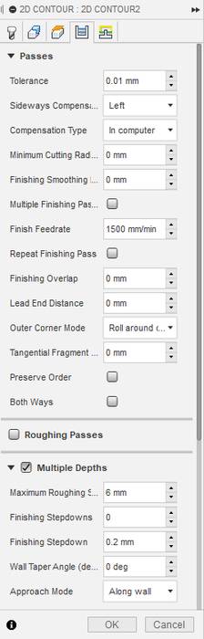
With respect to the number of passes the settings are as follows
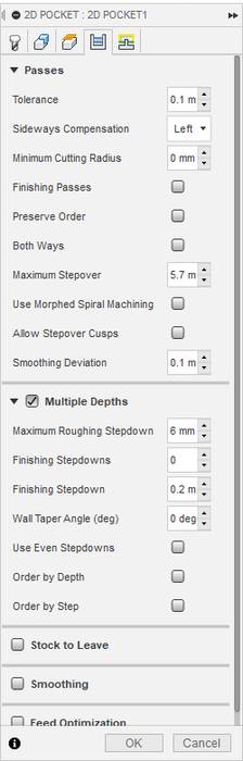
And the last tab remains the same.
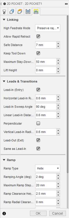
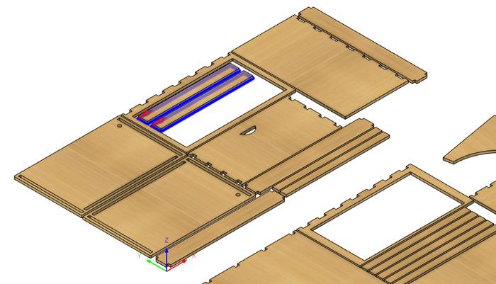
The final result of Pocket is as follows.
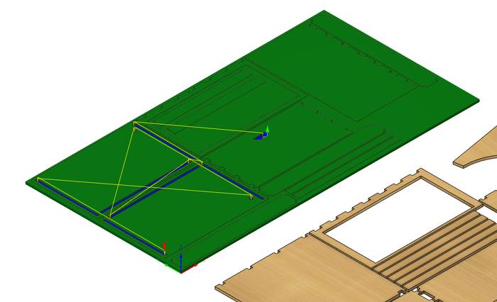
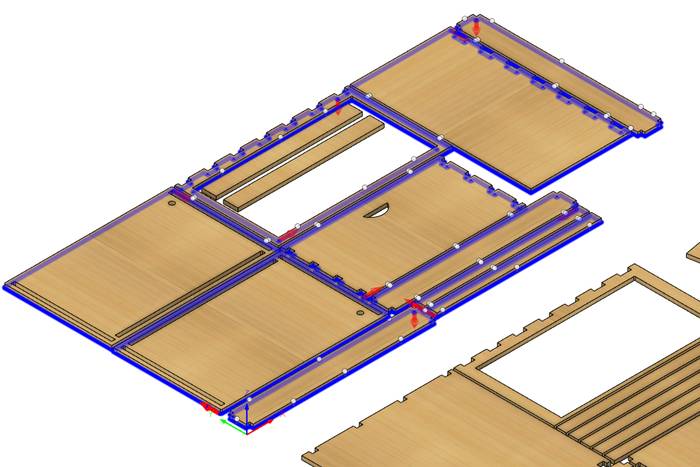
The next process to perform is Contour and with that you can perform the rest of the pending work to have all the pieces, but because there are some pieces that are contained in others it is necessary to apply several Contour jobs to ensure that all maintain their position and that the machining of some does not affect others.
In this occasion I am going to perform two contour jobs both with exactly the same parameters, only the selected geometry changes.
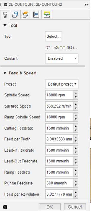
The speed and tool settings correspond to the following.
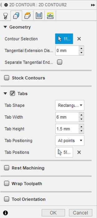
In the geometry tab is as follows
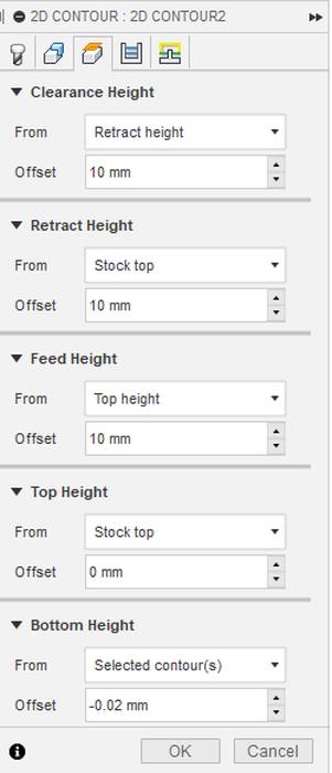
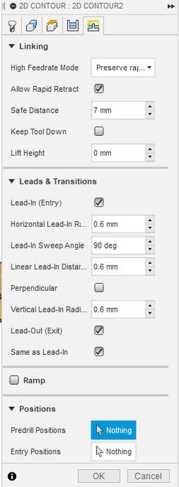
The safety distance, retraction and others are these.
In the raisins tab there are no special settings to take into account.
And the last tab remains the same.
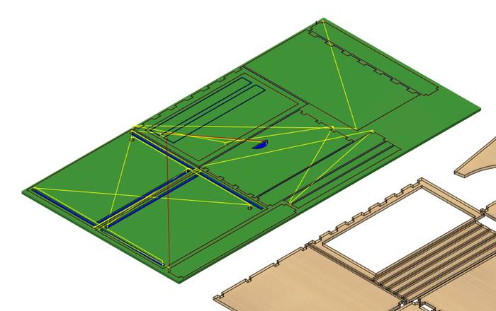
The final result is as shown below.
The milling process in my case started a little bit different since the sacrificial layer of the machine had to be changed because the previous one was already too worn out, so a new one was placed.
After placing it is necessary to make sure that it is completely flat, this is achieved by milling the entire surface with a Milling Bit dedicated to that job.
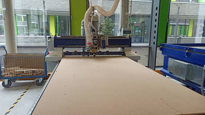
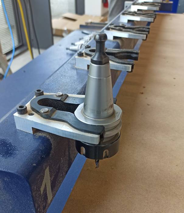
With the entire work surface flat, proceed to place the work tool in position 1 from where the machine will take it at startup.
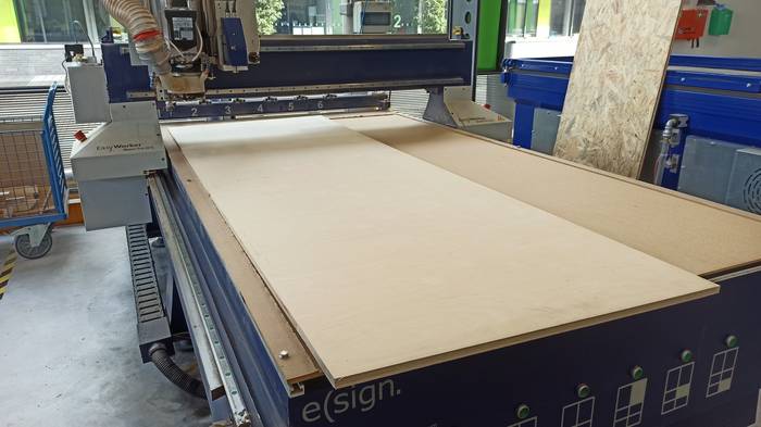
Next was to place the sheet of wood on the work surface.
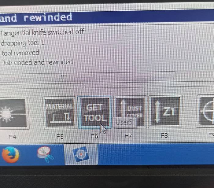
In the machine software, in the main window navigate to the menu called "User Menu".
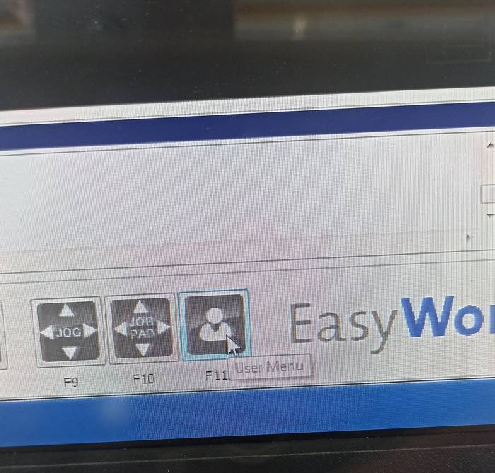
Then to the option "GET TOOL".
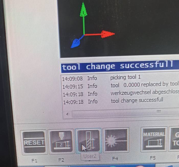
And select the F3 function
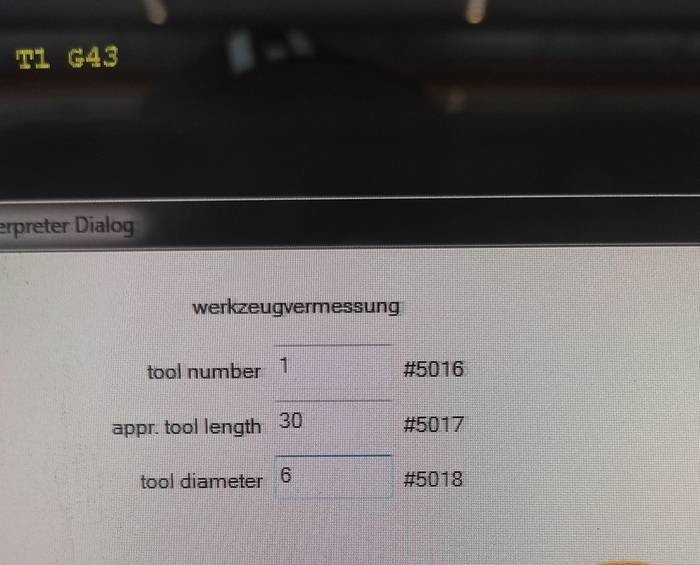
A dialog box will appear in which you must adjust the characteristics of the tool so that the machine will take it properly.
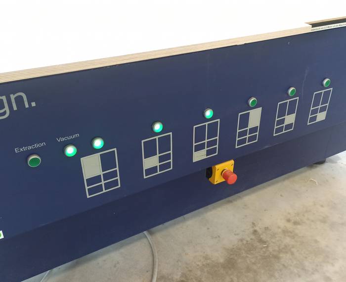
The clamping system I am using is Vacuum, activating only the areas where the wood sheet is located.
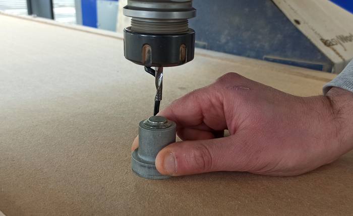
After the machine picks up the tool it is necessary to set the Z, this is possible using a mechanical sensor that is connected to the machine.
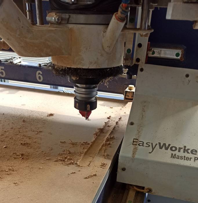
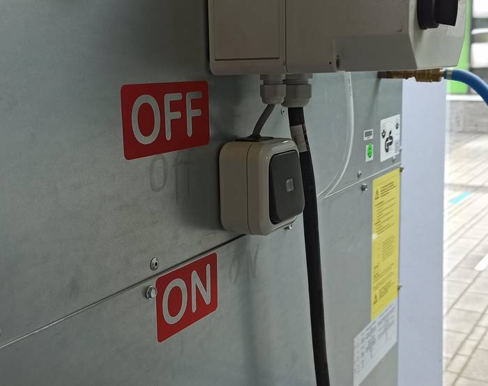
Before starting to mill, the extraction system must be activated to try to keep the working area clean.
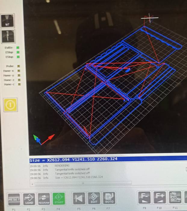
It only remains to load the file for milling and press Start.
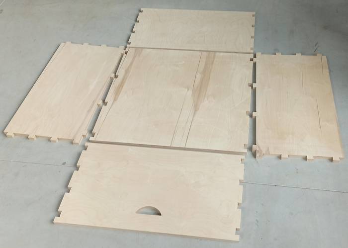
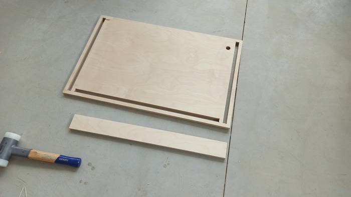
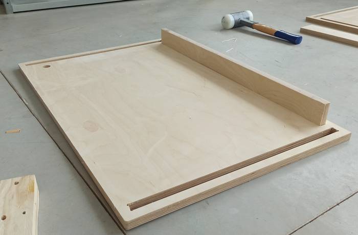
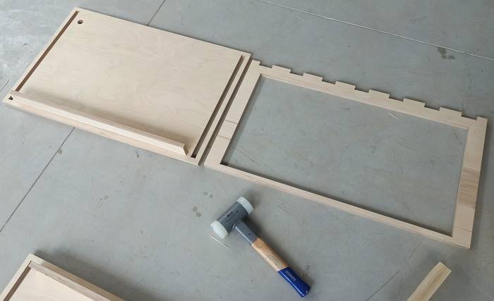
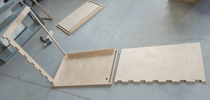
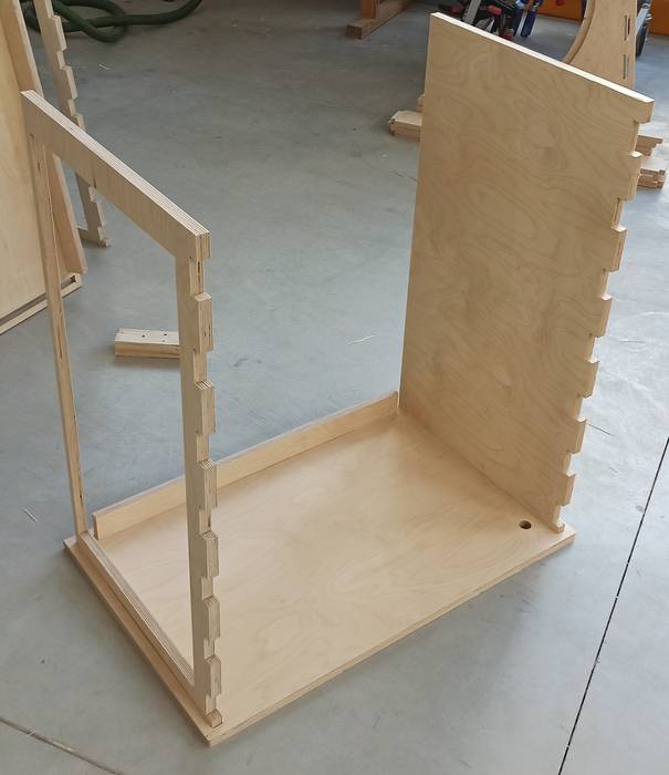
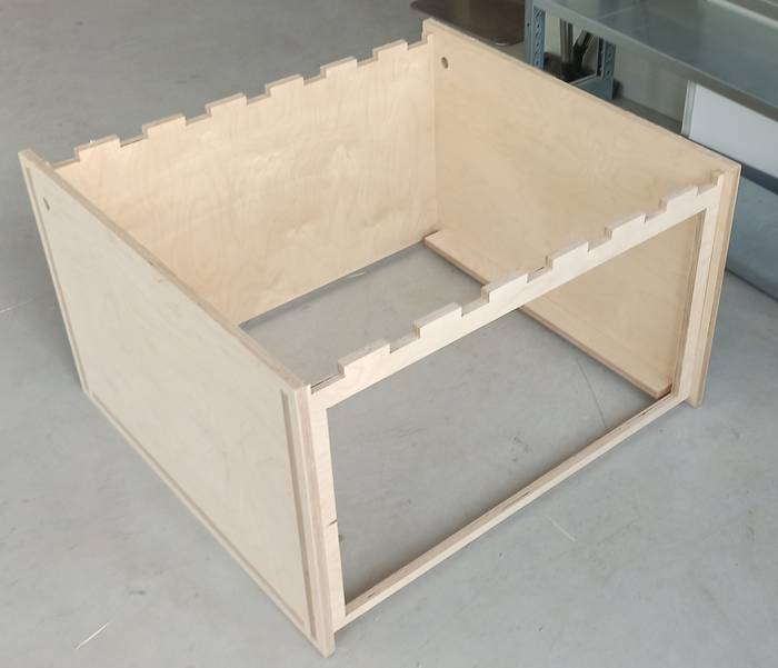
With all the parts ready the next thing to do is to assemble everything. During this process there is not much to explain, they are simply parts with fixed press-fit joints, so here is a sequence of images of the process.
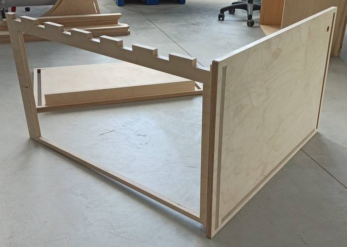
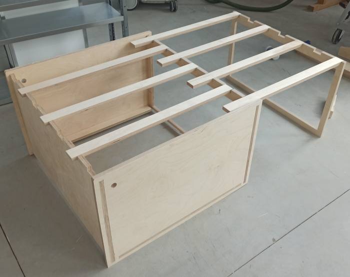
After some time assembling the final result is this.