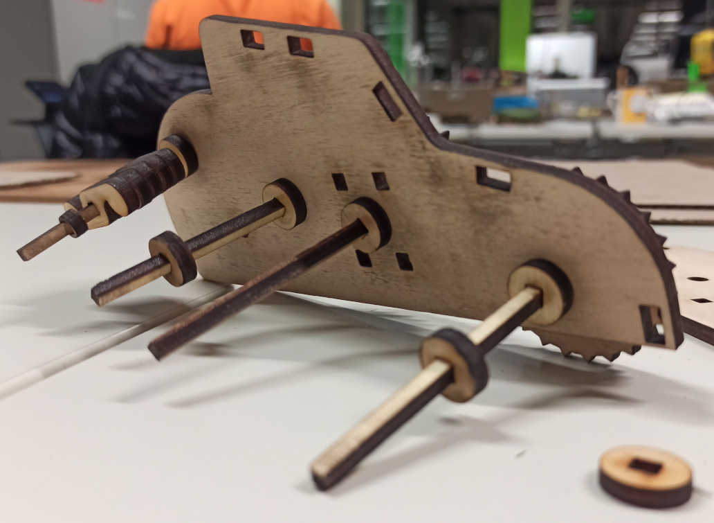
After thinking about some ideas about what to design I decided to make a small car with a gear mechanism that in the future will work to propel the car using a rubber band. BUT the problem was that I didn't know where to start, so before starting to design the 3D computer model I experimented a little with cardboard to give me a clearer idea of the sizes I would like and the proportions between the pieces, with the purpose of having a clearer idea of WHAT and HOW to design it.
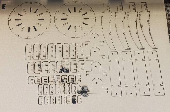
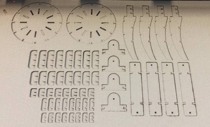
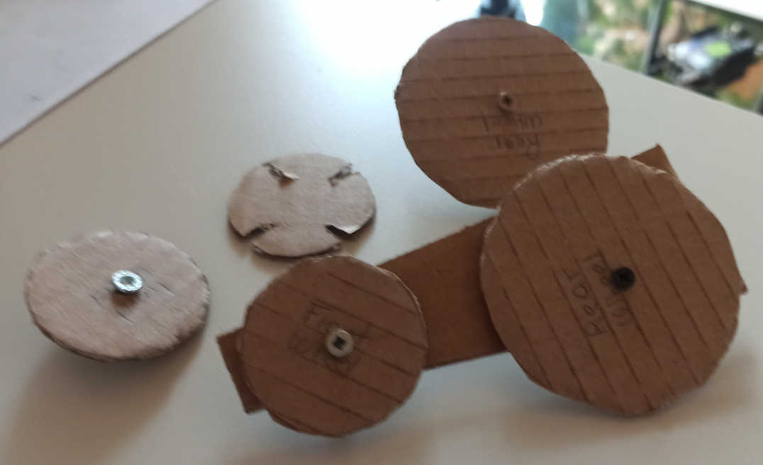
I cut two cardboard circles for the wheels as I wanted to give it a HOT ROD look.
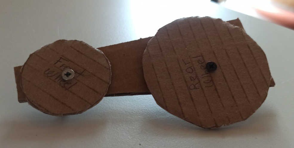
I cut several pieces to have a clearer reference of the proportions I wanted to give it initially.
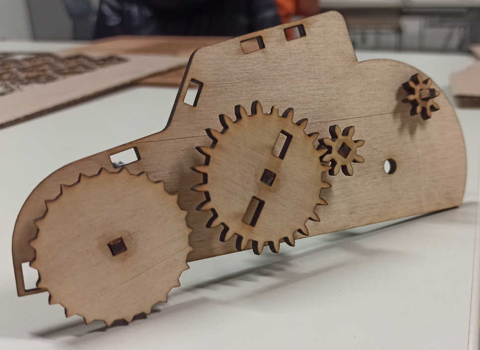
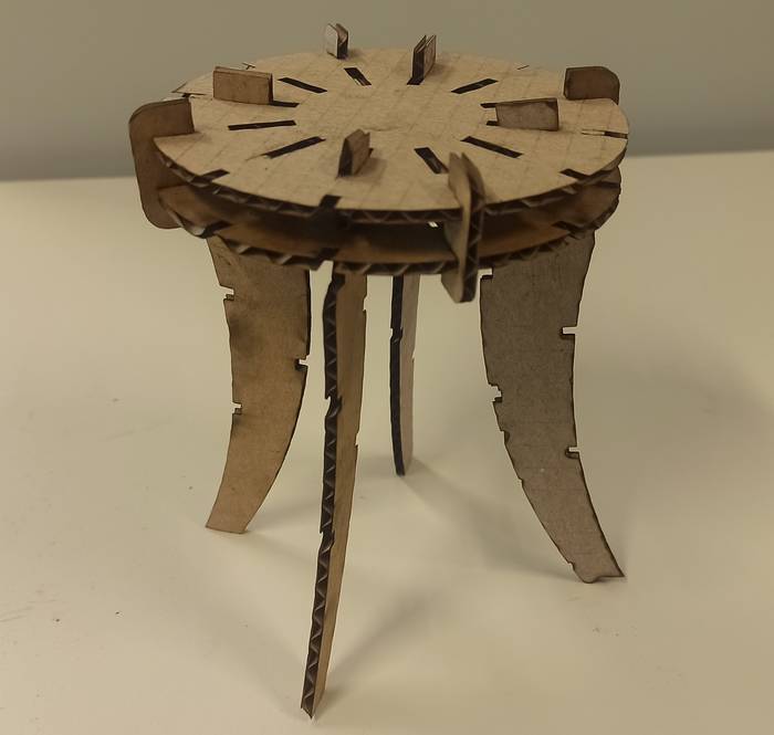
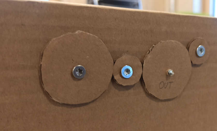
Since I wanted to give it a gear mechanism I made a very simple map of the gears and the distribution between them, this is the front view of the gear mechanism.
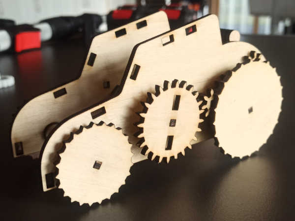
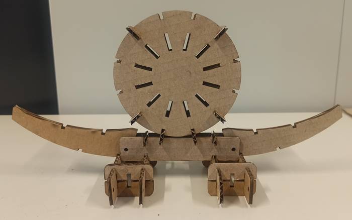
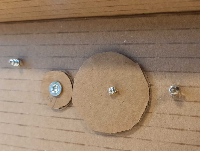
And this is the rear view of the mechanism.
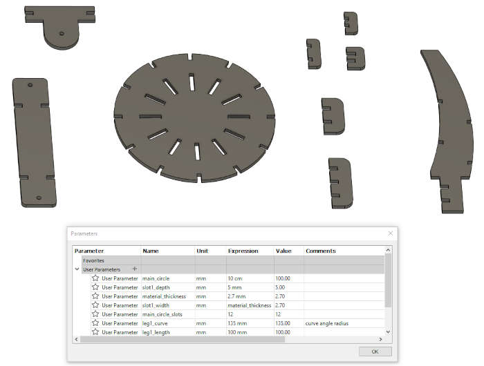
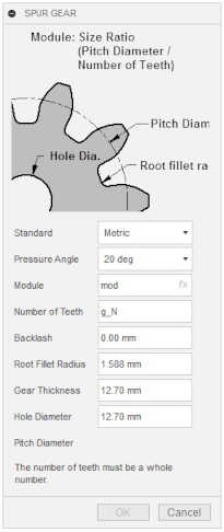
At this point I already had a very clear idea of what parts I had to design, some initial measures and the distribution of the pieces, but now the challenge was to parameterize the whole model. BUT the model contains gears that should also be parametric, so my first idea was simple, use the Fusion 360 gear generator and in the generator parameters assign variables declared by me, one called mod for the module and another g_N for the number of teeth.
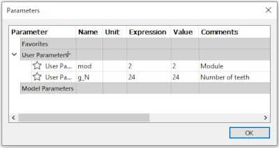
Then I set the variables in the generator but it tells me that the number of teeth should be a number, and in my parameter declaration it is!
So I decided to try with a fixed number of teeth and just parameterize the module.
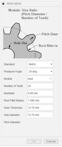
Still the generator didn't allow me to set the gearing. Conclusion you cannot parameterize the Fusion 360 gear generator.
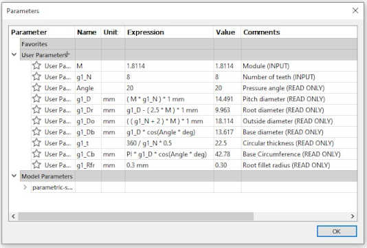
Seeing that the generator is not possible to parameterize it I decided to design my own gearing and parameterize it from design. For that I needed the formulas for a gear since I couldn't remember them clearly, but after a search on the internet I found this page (https://www.engineersedge.com/gear_formula.htm) that contains all the necessary equations.
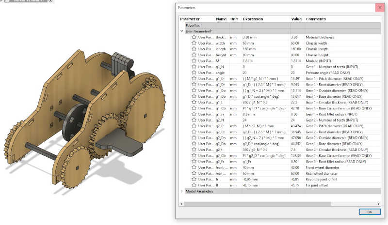
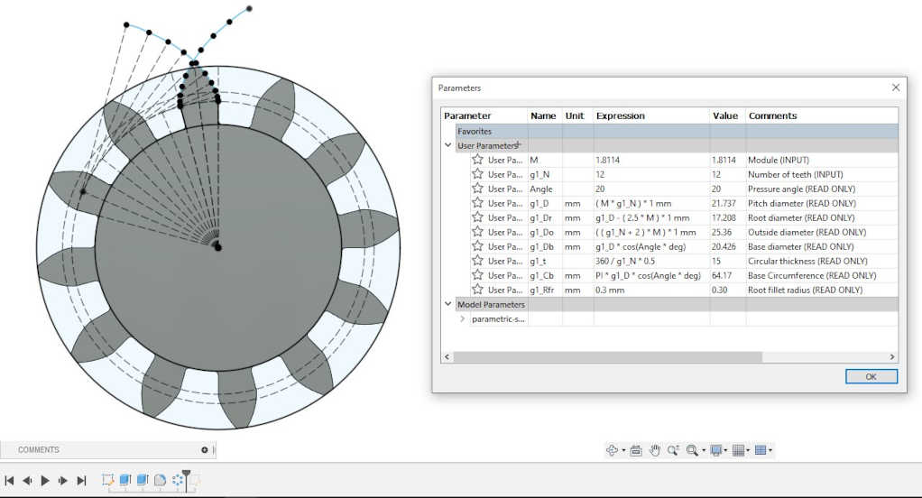
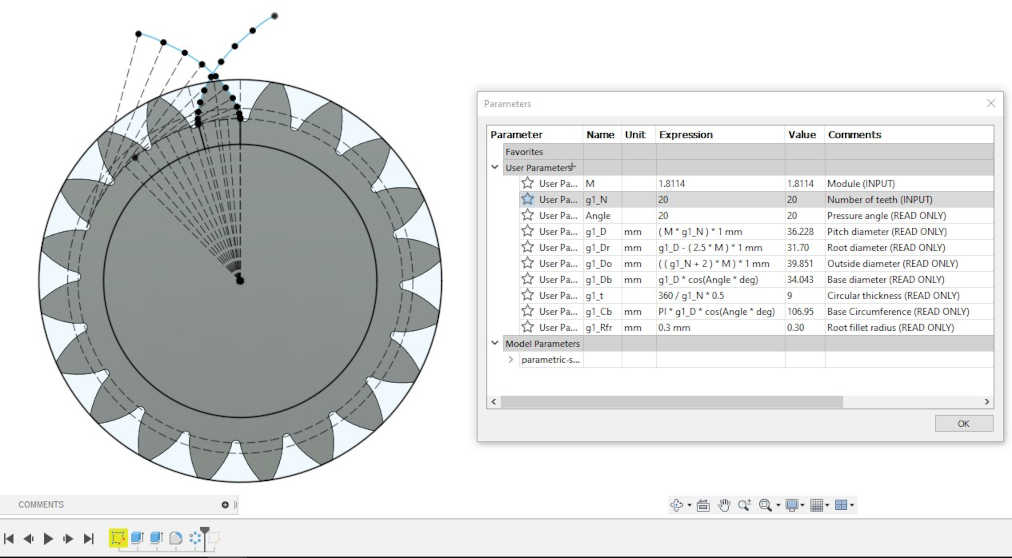
Now it was time to add the parameters of a gear that will allow me to generate it. This is the table of parameters with their corresponding equations.
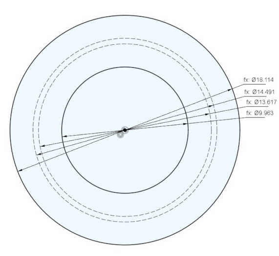
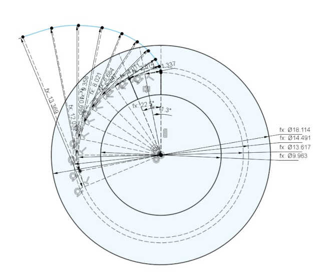
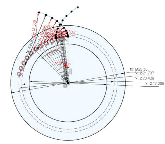
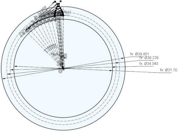
The construction circles for the gear are as follows
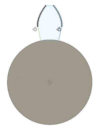
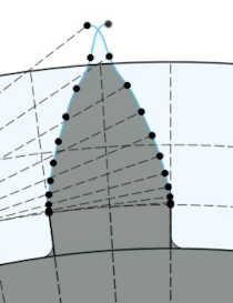
But now a new problem arises, THE TOOTH PROFILE! ... to give me an idea of how to metrically design the tooth profile I generated a gear with the integrated Fusion generator to see how the generator did it. That made me notice that the generator created a series of points that were joined by a spline.
The spline was not parametric! ... then I remembered that the profile of a gear tooth is generated using something called an INVOLUTE CURVE (https://en.wikipedia.org/wiki/Involute) that allows the contact between the splines to be smoother and the stress to be incremental, here a page that explains it in more detail (https://www.spiroidgearing.com/products/concurve/)
At this point my mind was saying "NEW CHALLENGE UNLOCKED", I had to think how to generate an involute curve in Fusion 360! ... Other more advanced CAD programs like Catia, Creo or Solidworks have support for generating curves from mathematical equations, this feature is known as "equation driven curve", in Creo it is achieved using the feature called "Relations" which allows us to write algorithms based on our parameters.
The solution I came up with was to generalize the involute curve using constraints in Fusion 360, for that I needed the equations that define the involute curve, but thanks to the internet I found this page that describes them very well (https://khkgears.net/new/gear_knowledge/gear_technical_reference/involute_gear_profile.html). Now it was a matter of converting those equations to a parametric form using constraints.
The involute curve looks very promising!
Now it's just a matter of mirroring the curve and extruding. The result looks amazing!
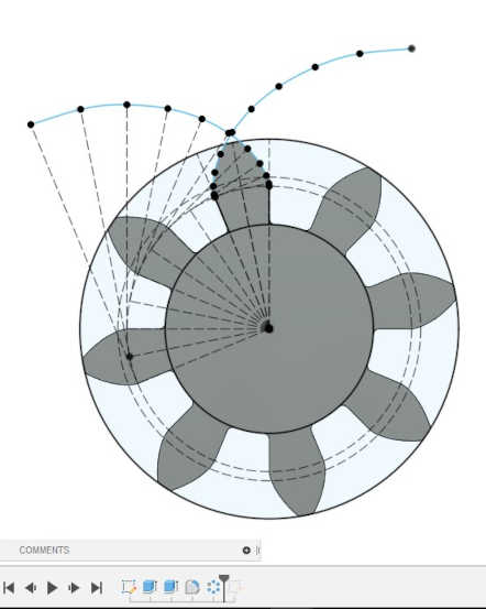
Now it's time to test if the parameters work by increasing the number of teeth from 8 to 12.
Incredible it stays parametric! ... I will continue to increase the number of teeth from 12 to 20.
It seems to work but a warning appears in the sketch.
Some dimensions appear in red, I didn't know why so I double clicked on one of them and verified that the parameter was ok, and it was ok but when I hit enter to exit the dimension edit ALL was corrected! ... it seems that there is an error in Fusion when updating the new values to the dimensions.
After correcting that little bug everything worked fine again.
But if I continue to increase the number of teeth the involute curve spline starts to deform.
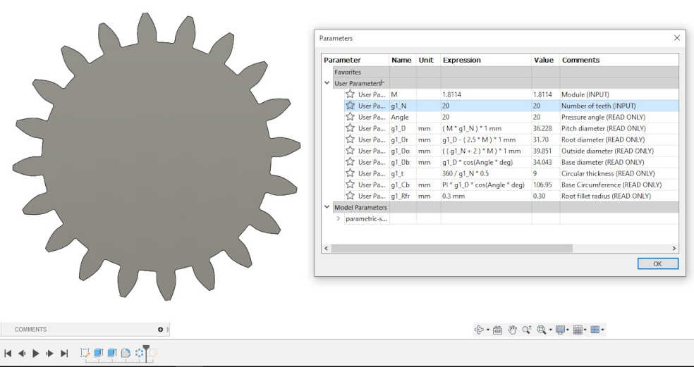
After a few hours of design and parameterization the result is as follows