In the area of vectorial design I have some years of experience working with software like Illustrator and CorelDraw, but since I finished my license I use web based software like Gravit Designer and Figma, lately I use Figma a lot because it allows me to share projects and add more people to collaborate in the same design, besides it has a very simple and intuitive interface that allows me to make designs very fast and without much effort. Many times I have tried to incorporate Inkscape into my workflow but at least for me I feel that the user experience is not very intuitive, but from time to time I use it to do very specific things and take advantage of the plugins it has.
This time I am using Figma.
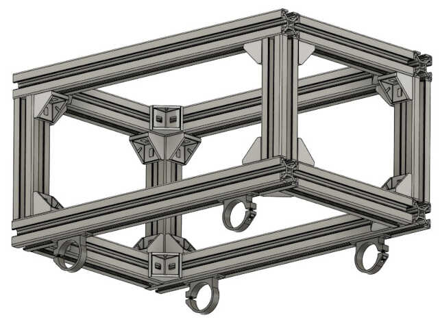
For this section of the assignment I decided to create a vector version of the sketch I made last week for the project description, for that I started with the basic shapes of the drawing without adding much detail, this with the objective of delimiting the figures I needed to use and then stylize them a little. Also at this point the color does not play an important role so I simply used grays to represent the brightest and darkest areas, and activated the external lines of the shapes to clearly see their limits.
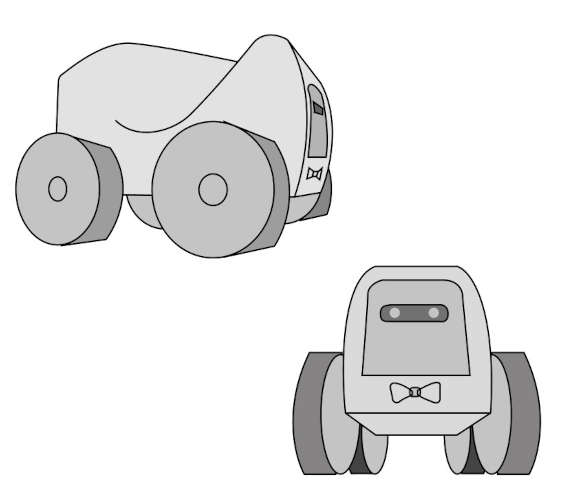
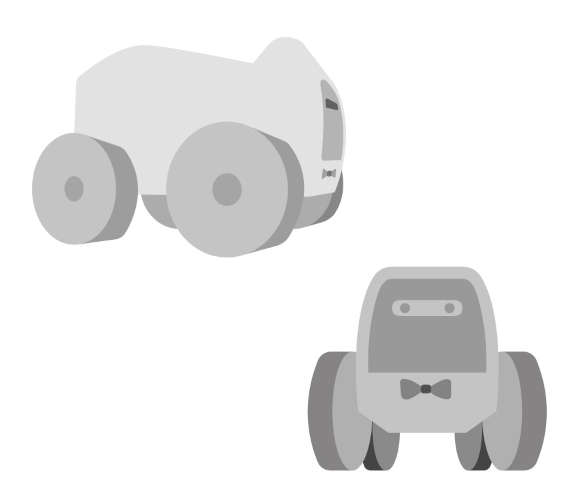
Then deactivate the lines to see the result of the basic shapes.
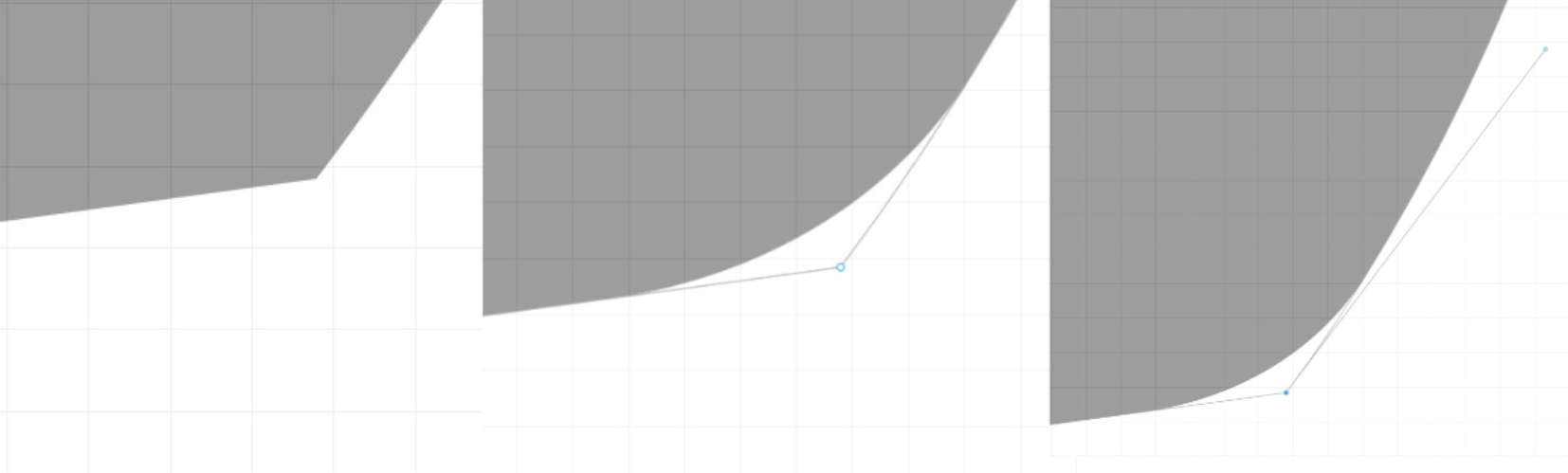
Now it's time to start detailing the basic shapes, I decided to start with the wheels which have some very sharp corners that need to be smoothed, this was done using the rounded corners function that any vector software has, the result is shown in the image below.
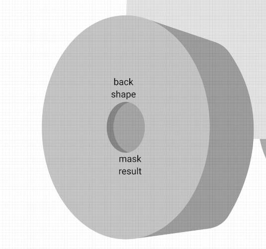
Although the vectorial design is a type of 2D design using shadows you can create the sensation of three-dimensionality, for that I use a function that is present in all vectorial softwares, that function is called masks, it consists of using a form that defines the area then another form that is the one that we want to insert in the mask, if we select the two it creates a figure that we can use as a shadow for the center area of the wheel.
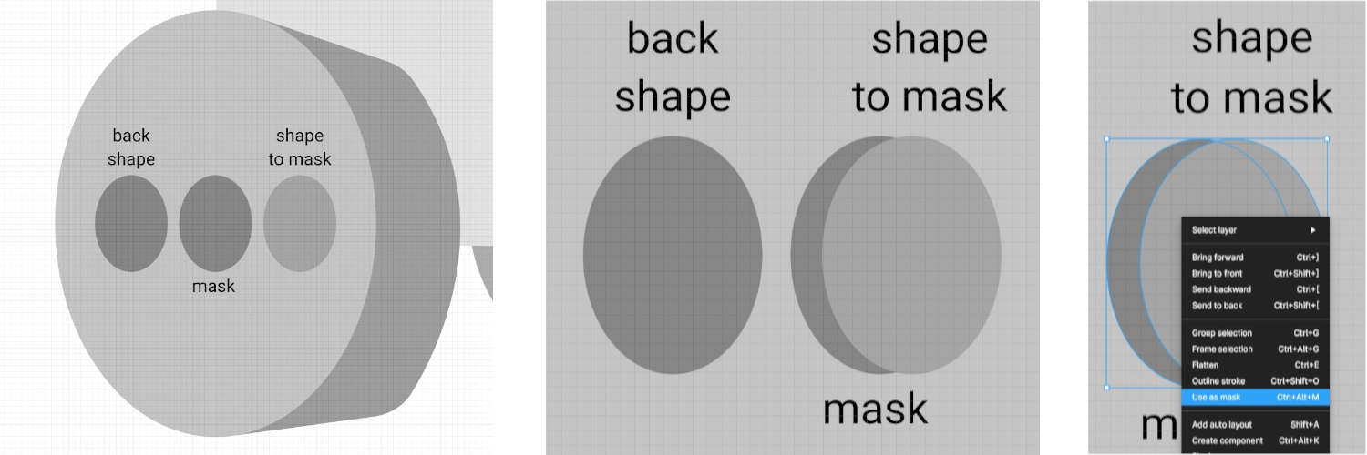
The result is shown in the following image.
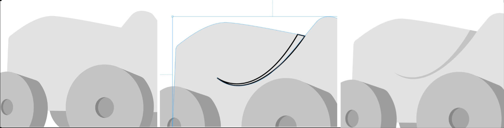
Shadows can not only be achieved using masks, it is also possible to create a shape with the shape of the shadows we need, in the following image I create a shape that I then use to create a relief and separate two sections of the robot's body.
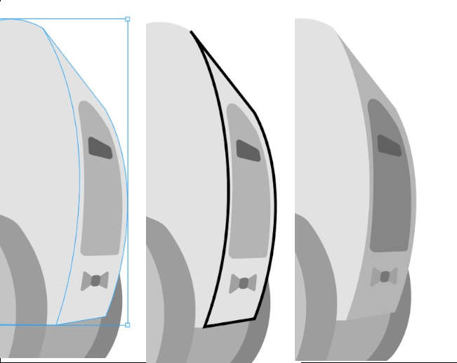
In the next image I use the same technique to create the shadow of the front area of the robot.
At this point we begin to notice a little three-dimensionality in the figures but the shadows are not always hard in the sense that they have the same intensity as the ones we have created so far, the shadows also have a gradient that makes them more intense in the places where it originates and as it spreads it becomes more diffuse and loses intensity. This same effect can be simulated using gradient shapes.
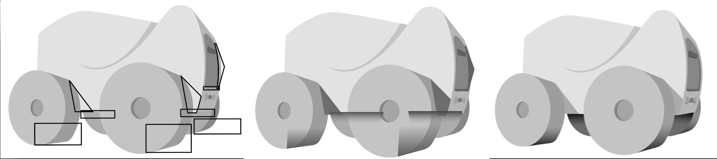
In the following image I make basic shapes in the areas that I want to apply shadows, after those I apply a fill but not a solid fill but a linear gradient fill (center image), you can see the places where the shadows are but they do not integrate very well the design, that is because the last step is to apply masks with respect to the figure that we want to shade, after applying the mask the result is much better.
In the following image you can see a comparison between the way we started and the final result by applying shadows and mascaras to add more volume.
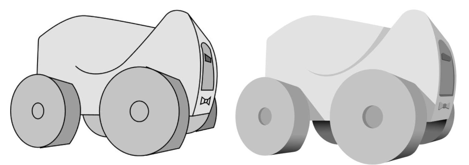
Now it was just a matter of continuing to repeat the process with the other view of the robot.
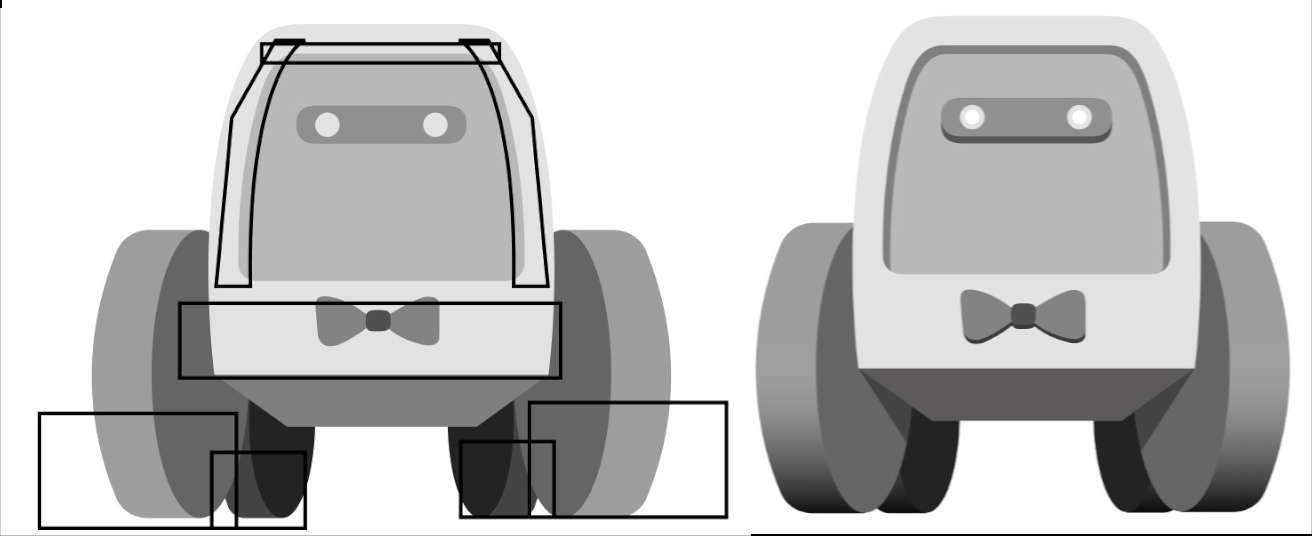
The final result of both robot views is shown below.