Computer-Controlled Machining
Assignment Requirements:
- Test runout, alignment, speeds, feeds, and toolpaths for your machine.
- Document your work (in a group or individually)
- Make (design+mill+assemble) something big.
Learning Outcomes:
Steps in General:
- Step(1): Testing runout, alignment, speeds, feeds, and toolpaths for Simplex CNC Router machine
- Step(2): Designing the stool on Fusion 360
- Step(3): Preparing CAM on ARTCAM
- Step(4): Operating the CNC Router
- Step(5): Assembly
Steps in Details:
Step(1): Testing runout, alignment, speeds, feeds, and toolpaths for Simplex CNC Router machine
Overview
- We selected an Egyptian CNC Router Machine which is Simplex.
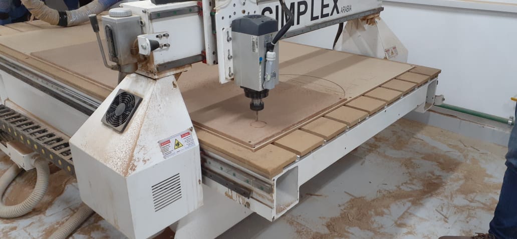
- It is operated with Mach3, it is 250 cm * 130 cm.
- We tested the runout, alignment, speeds, feeds and toolpaths in the group assignment page.
Workflow of a Typical CNC Project
- Concept: You should have an idea of what you want to make and it is recommended to make a solid draft using pencil and paper.
- Design (CAD): Either 2D or 3D, you have to design on a cad software like Fusion 360, FreeCAD, SolidWorks, ...etc. and have the digital file in a supported format.
- Material Selection: Choose the suitable material for the design and the machining type.
- Toolpath (CAM): here you select the appropriate cutting tool and set its cutting parameters, select the toolpath type either 2d or 3d, select the toolpath operation, setup the material and its orientation, simulate the program and export the supported code for the machine.
- Machining: Load the codes into the operating software, fasten the material on the machine bed, fix the tool in the spindle, set the origin points for the axes, dry run then actual run.
- Finishing & Assembly: like sanding, painting, or any required post processing operations.
Safety Tips with the CNC Router
- Never leave the room while the machine is routing.
- Do not put any part of your body closer than 6 inches to the cutting tool when it is moving.
- Always use eye and hearing protection When the machine is working.
- If the bit is acting up or breaks, shut down the machine straight away.
- Do not force material into the router.
- Make sure that all workpieces are securely clamped down.
- Always make sure you have inserted the correct bit for the job you are doing.
- Do not operate a CNC router in a damp or moist environment.
- Clean the machine and the floor around it after every use.
Designing & Creating Toolpaths
- We used ArtCAM software to design the circles and generate the toolpaths and gcodes.
- We created a new model with 1220 mm width and 2440 mm height (this is the standard MDF size), set the unit to mm and made the origin at the bottom left corner of the wood board.
- In the 2D View-Bitmap Layer, we created a circle of 100 mm diameter close to the bootom left side.
- Then we created 4 more circles with same diameter and positioed them near the first one.
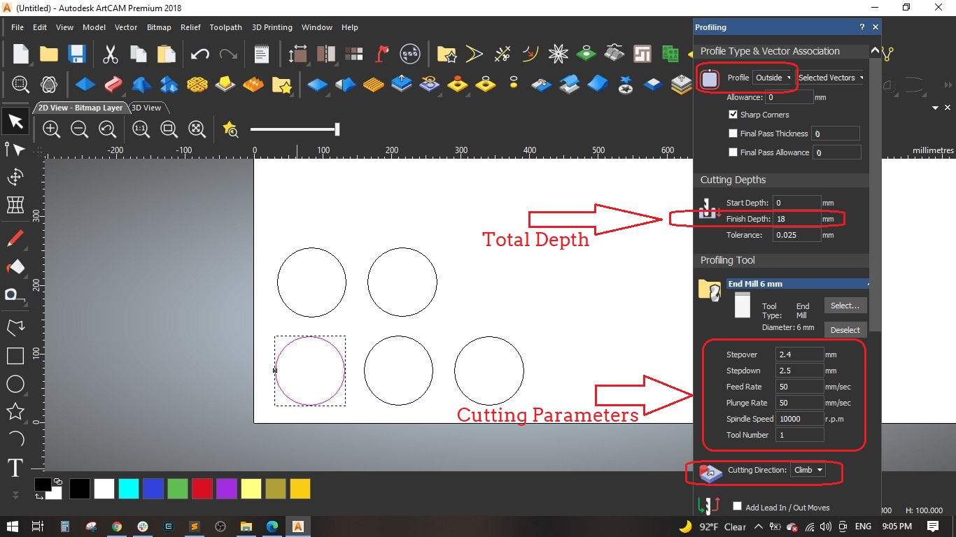
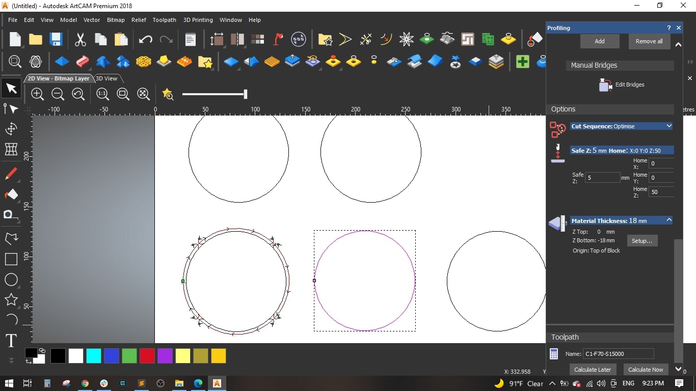
- Selected the first circle, selected the toolpath button and selected the Create Profile Toolpath from the 2D Toolpaths section.
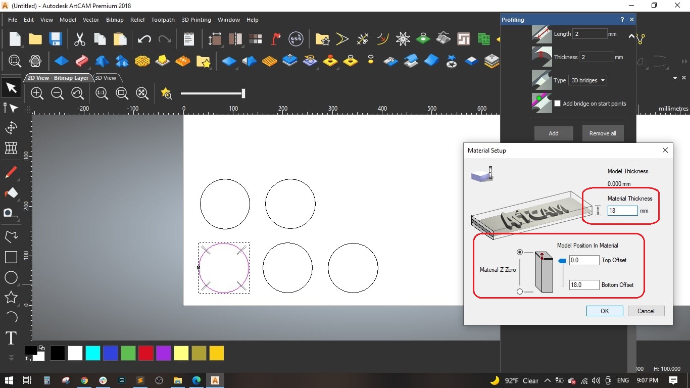
- We selected Outside for the profile, finish depth to 18 mm (as the MDF sheet thickness).
-
Selected the 6 mm end mill from the tool library ans det the following parameters for the tool:
- Stepover: 2.4 mm [is the distance the center of the bit moves horizontally for each pass]
- Stepdown: 2.5 mm [Maximum Z depth the tool should cut on each pass]
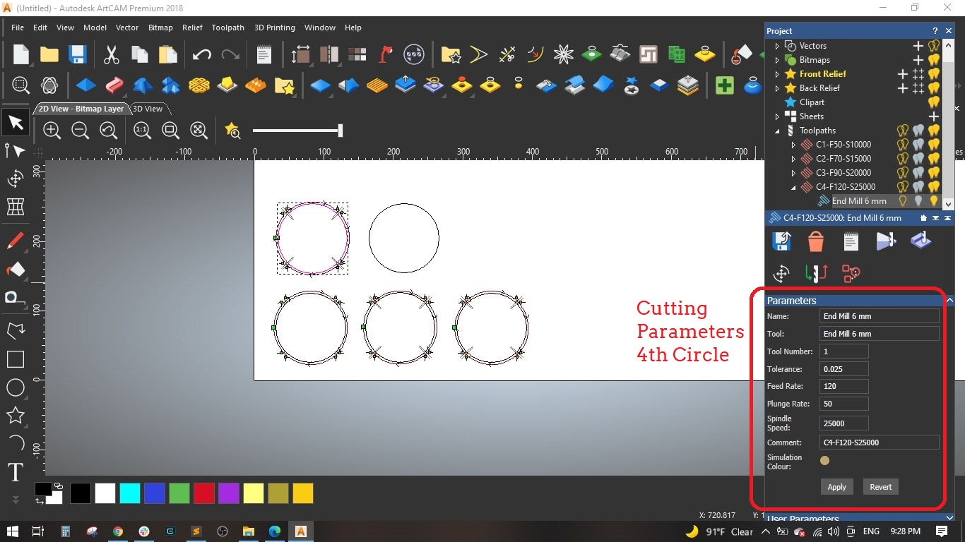
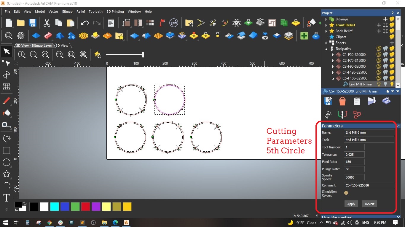
- Feed Rate: 50 mm/sec [ is the maximum speed the router bit will move through the material when cutting in a horizontal direction]
- Plunge Rate: 50 mm/sec [is the maximum speed the router bit will move through the material when cutting in a vertical or angled direction]
- Spindle Speed: 10000 r.p.m [is the rotational spped of the spindle]
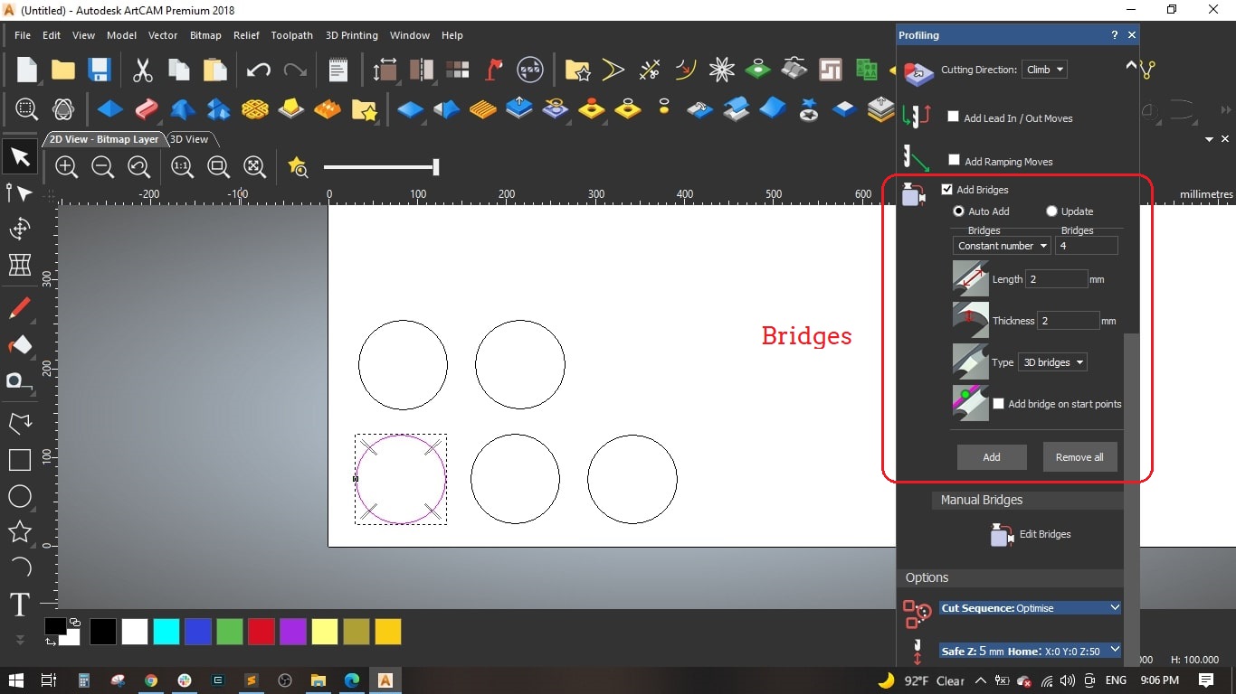
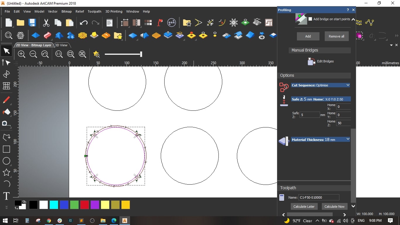
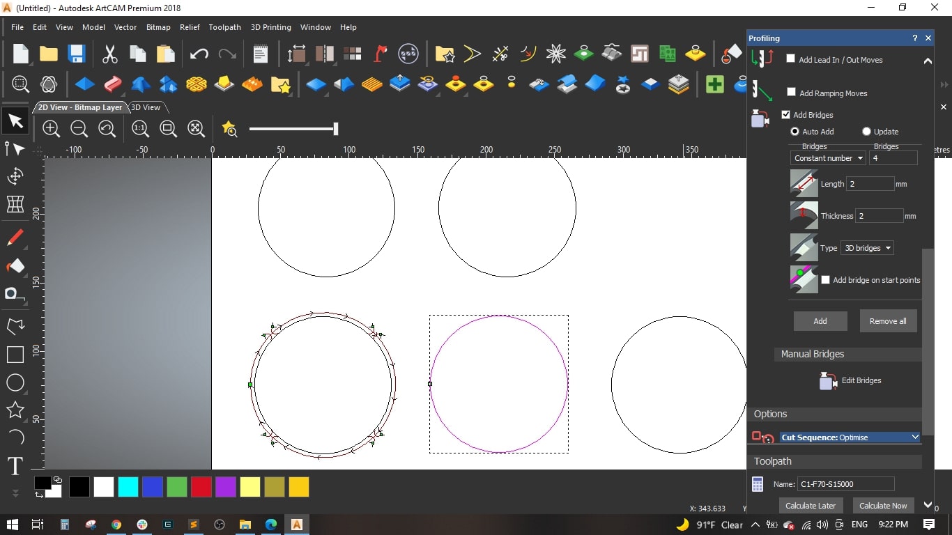
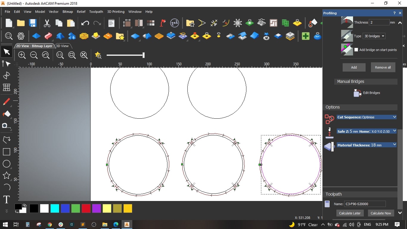
- We made some bridges to make sure the cut part is slightly fixed with the main board and to maintain the cutting tool, we made 4 bridges, each bridge has 3 mm length and 2 mm thickness and selected the 3d type.
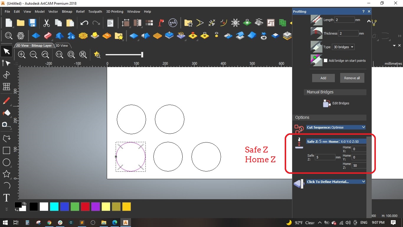
- It is impotant to set the home and safe Z, we set the home position of Z to 50 mm above the board and the safe Z while rapid moving to 5 mm.
- We used 18 mm MDF sheet and by default we set the Z zero on the top of the sheet.
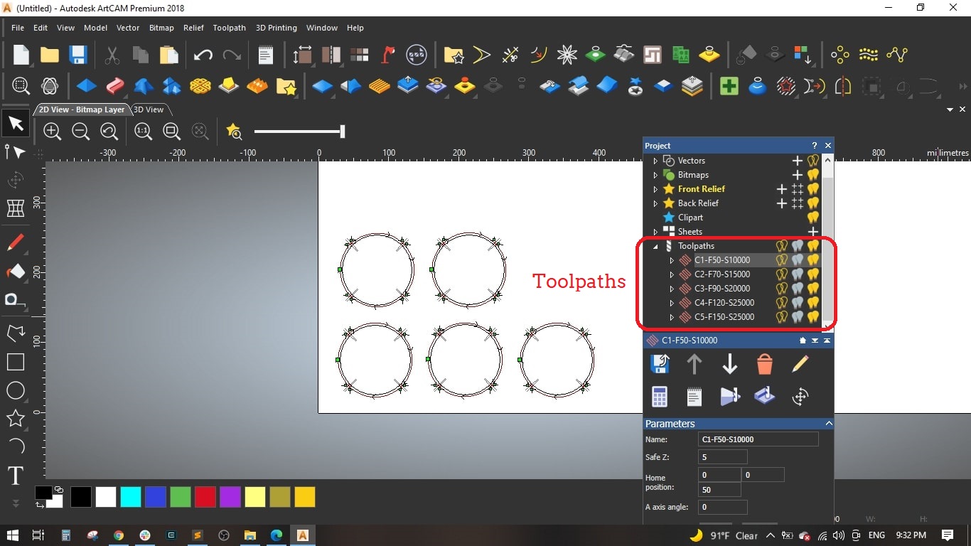
- Named the Toolpath "C1-F50-S10000" and calculated it.
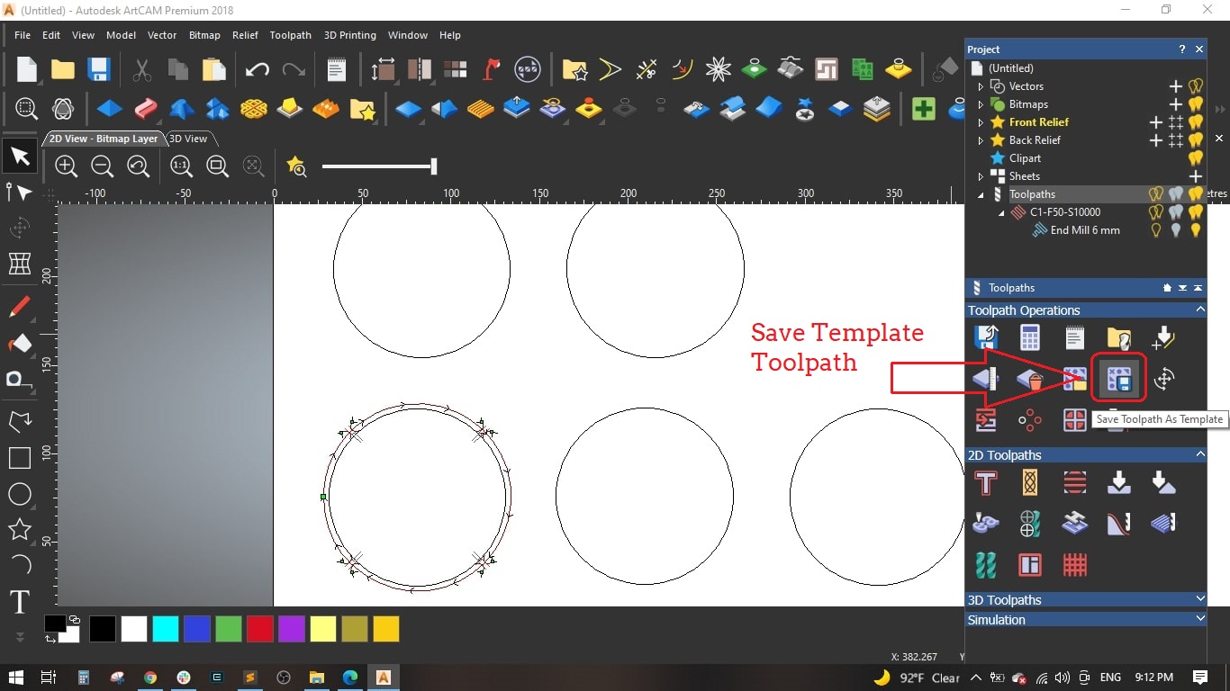
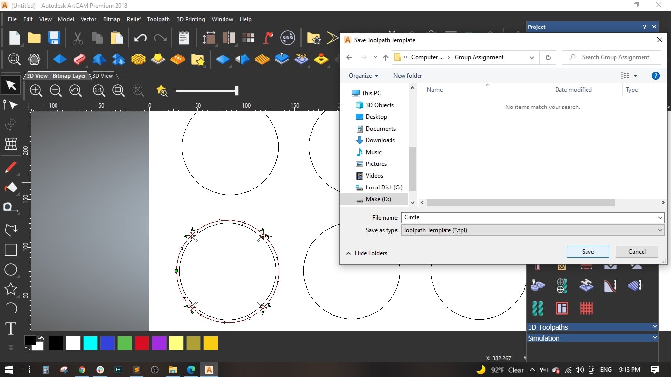
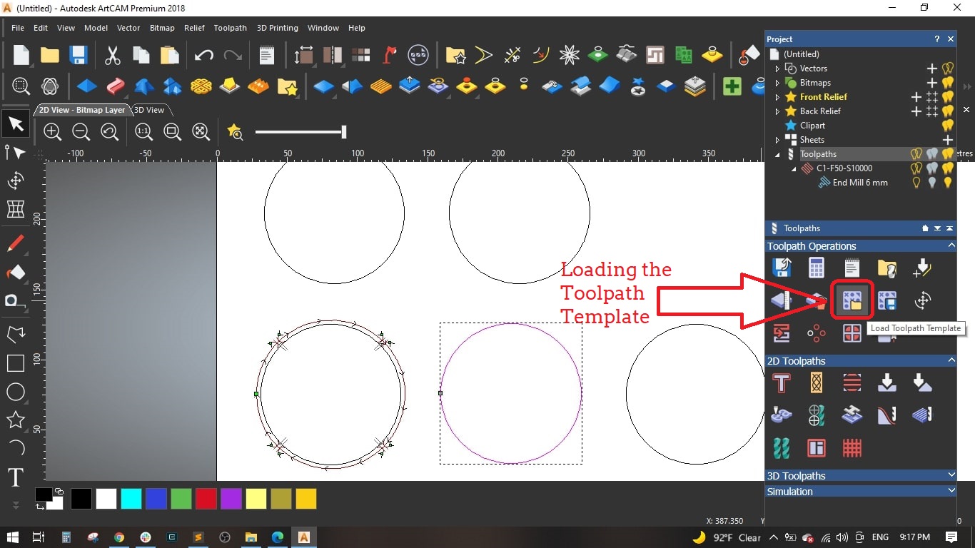
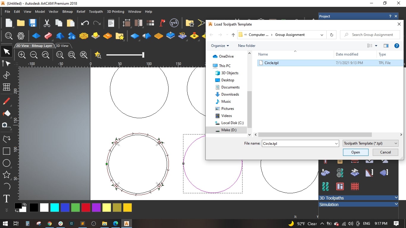
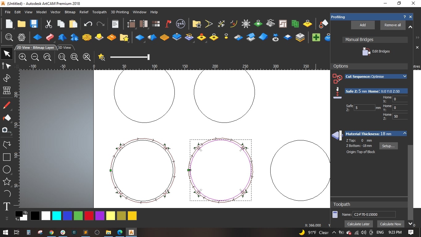
- To save time and effort, we saved the genarated toolpath as template to be used with the remaining circles and then edit some cutting values.
- Loaded the previously saved toolpath template and selected the second circle.
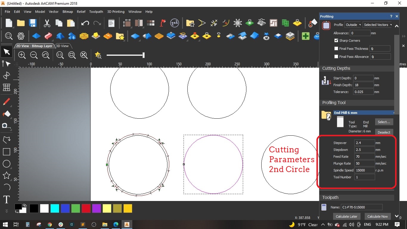
- The change we made is the Feed rate to be 70 mm and the Spindle speed to be 15000 r.p.m and used the remaining default settings as the first circle.
- Named the toolpath "C2-F70-S15000" and calculated it.
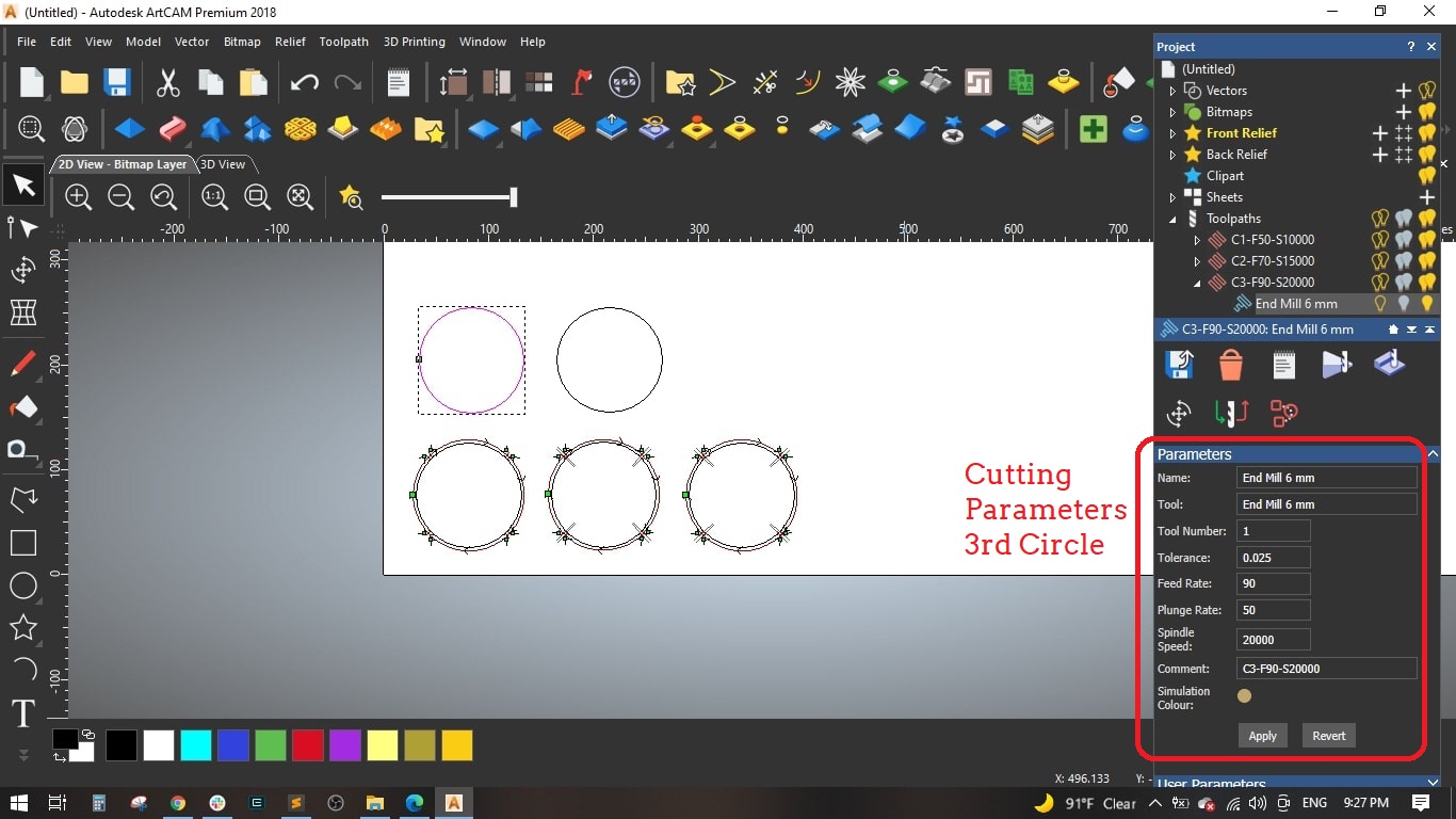
- We made the same for the remaining circles with the following change:
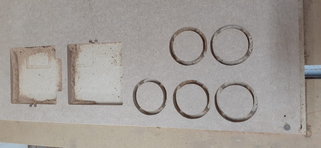
- Circle (3): Feed Rate = 90 mm/sec and Spindle speed = 20000 mm/sec
- Circle (4): Feed Rate = 120 mm/sec and Spindle speed = 25000 mm/sec
- Circle (5): Feed Rate = 150 mm/sec and Spindle speed = 30000 mm/sec
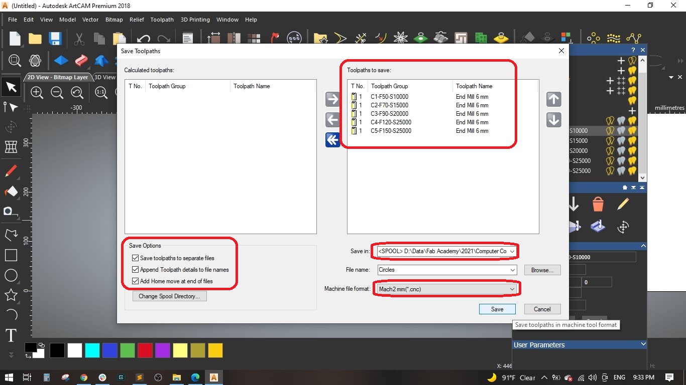
- Finally, we saved the 5 toolpaths to separate files and selected Mach2 mm(*.cnc) as the machine file format.
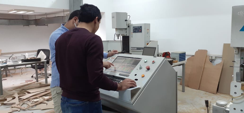
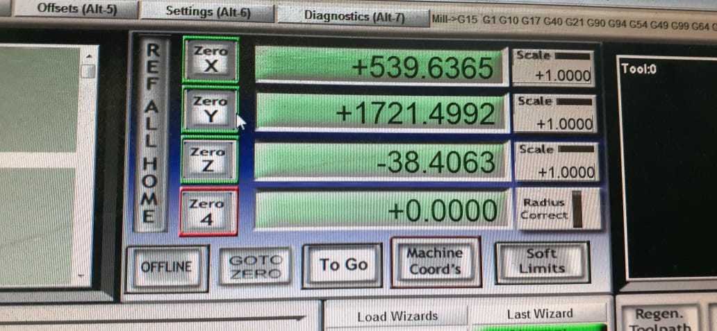
- We used Mach3 software to load the .cnc files and operate the machine.
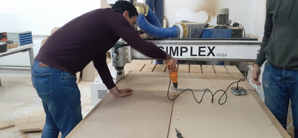
- We moved the spindle to the bottom left corner and moved the z down to be directly above the sheet and set Zero for the 3 axes.
- Loaded the first toolpath (first circle) into Mach3 and started the cycle.
- We repeated the same opeartion to all the 5 circles.
- The perfect settings for cutting the MDF is Feed Rate = 90 mm/sec and Spindle Speed = 20000 r.p.m
- I decided to use the parametric design feature in Fusion to be able to scale up or down the stool to fit all preferences.
- The parameters are: Stool Diameter, Stool Height, Stool Leg, Material Thickness, Tolerance and Dogbone.
- I created a sketch on the front plane and drawed the main shape of the leg, it is a simple one.
- I set the stool height to 500 mm, Stool Diameter to 450 mm.
- Then extruded the leg to the material thickness which was 18 mm
- For leg 2, I made a copy of leg1 and rotated it around the z-axis.
- I drawed a rectangle with the material thicness to form the slot in leg 1.
- Extruded it to the material thickness.
- I used the combine tool to perform the cutting operation between the two legs to have a slot in leg 2.
- Now leg 1 and leg 2 have a slot for fitting together.
- I created a sketch on the top plane and drawed a circle of 450 mm diameter.
- I used the projection tool to project the the intersection of legs with the seat.
- Extruded the seat and the cross-shape.
- I made the dogbone shape at each corner and cut extruded it.
- I also made the dogbone on the 2 legs to have better fitting.
- I made a fillet of 50 mm in each corner of the legs in order not to have sharp corners.
- Finally, I exported 3 .DXF files and ready for the CAM operations
- I opened ARTCAM and created a new model, I will be using 18 mm MDF sheet with its standard dimensions of 122 cm * 244 cm
- Set the units to mm amd the job origin to the left bottom corner.
- Then started importing the 3 .DXF files by dagging and dropping in the workarea.
- I selected the cross-shape in the seat, selected Inside Profile and set the finish depth to 18 mm.
-
I selected a 6 mm End Mill and set the cutting parameters as follows,
- Stepover = 2.4 mm
- Stepdown = 2.5 mm
- Feed Rate = 76 mm/sec
- Plunge Rate = 50 mm/sec
- Spindle Speed = 15000 rpm
- I added bridges so as to fix the cut part with the board with tinny tabs.
- Material setup: Thickness = 18 mm and the material Z zero to the top.
- Named the toolpath with Cross and pressed Calculate Now
- I selected the legs and seat without the cross-shape and selected Outside Profile
- Set the same parameters as the previous toolpath, named it Seat2legs and pressed Calculate Now
- Finally, I saved the toolpaths. I selected Mach2 mm(*.cnc) as machine file format.
- I uploaded the .cnc files on the CNC Router controller.
- Then I fixed the 18 mm MDF sheet on the machine bed using nails.
- Then I loaded the 6 mm end mill to the spindle.
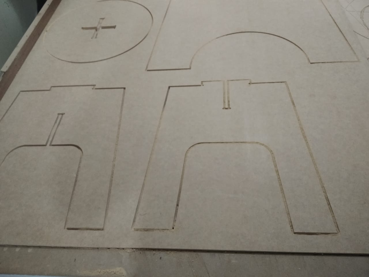
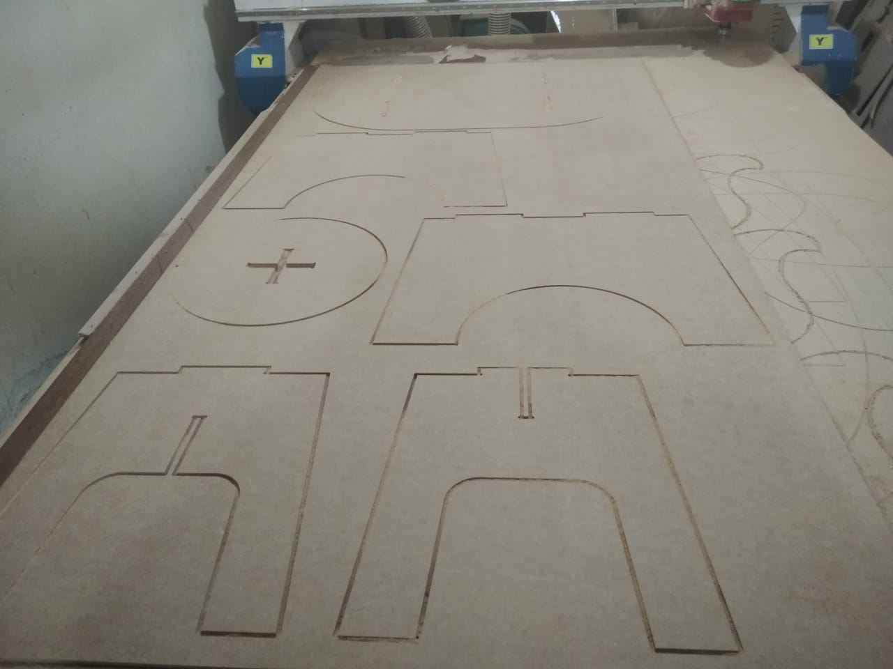
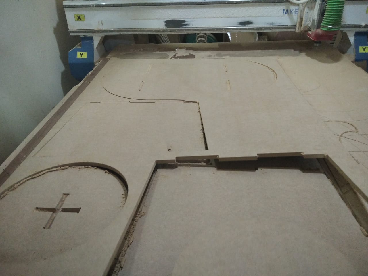
- Run the first toolpath which is the inside slot in the seat.
- Finally, I run the second toolpath which is the outside of the seat and legs.
- I removed the finished parts from the machine and they are ready for assembly.
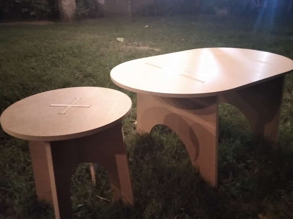
- I assembled the 2 legs and put the seat above them.
- It is a nice stool for children.
- Issue#1: For the first run, the slot had a big clearance and it did not fit well.
- Solution#1: I decreased the clearance distance in Fusion 360 and exported the dxf files to the ArtCam, then sent the .cnc files to the machine and they are now fitting well
- Issue#2: The MDF sheet does not have an accurate thickness along its length.
- Solution#2: I had to consider the medium thickness and run some tests to obtain perfect cutting and fitting.



Mach3 Opeartion


Results

Step(2): Designing the stool on Fusion 360


Preparing CAM on ARTCAM


Step(4): Operating the CNC Router



Step(5): Assembly

