Networking and Communications
Assignment Requirements:
- Send a message between two projects.
- Design, build, and connect wired or wireless node(s) with network or bus addresses.
Learning Outcomes:
Steps in General:
- Step(1): Designing the circuits on KiCAD
- Step(2): Preparing the png files on Gerbv and GIMP
- Step(3): PCBs Fabrication, Assembly and Soldering
- Step(4): Circuit Programming and Communication Testing
Introduction
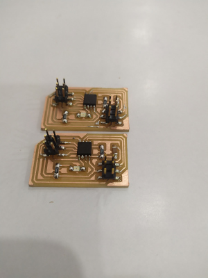
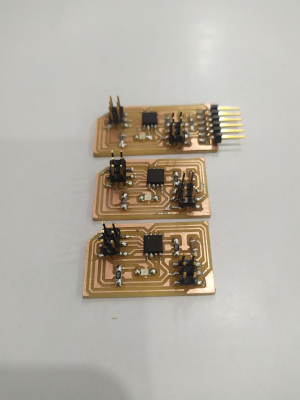
In this week I decided to make a wired communication using the UART method, I desiged a bridge and 2 nodes, programed each circuit and did the communication well.Steps in Details:
Step(1): Designing the circuits on KiCAD
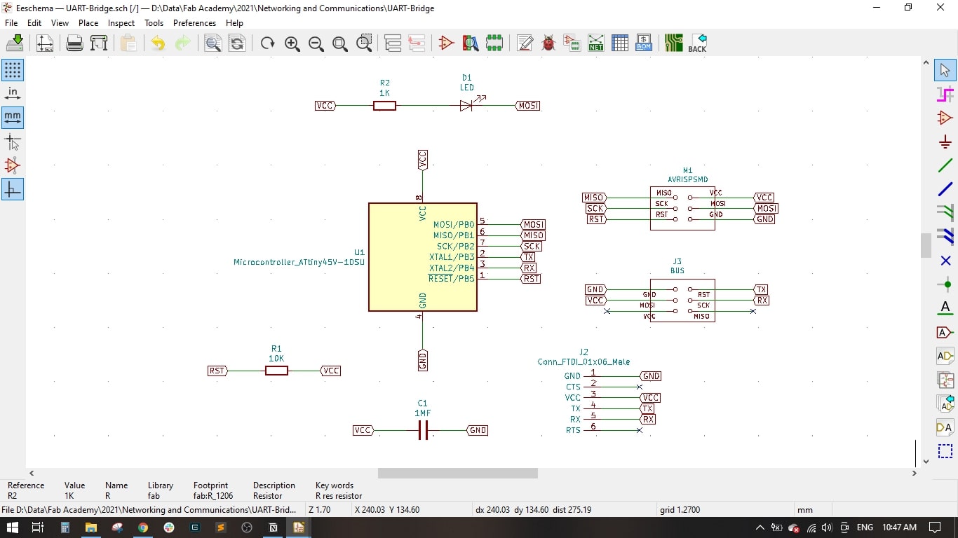
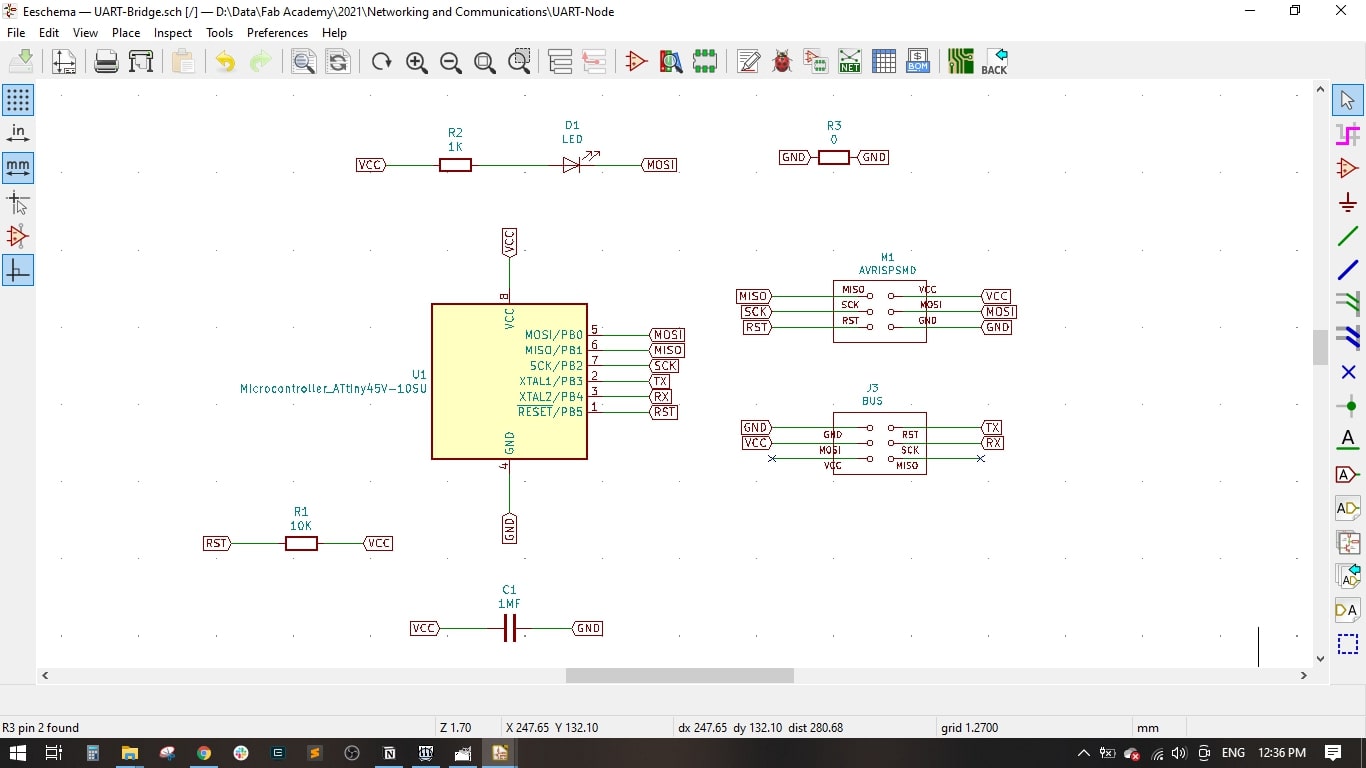
- Firstly, I began designing the bridge then the nodes.
- I imported the components into the KiCAD Shematic and did the wiring as shown
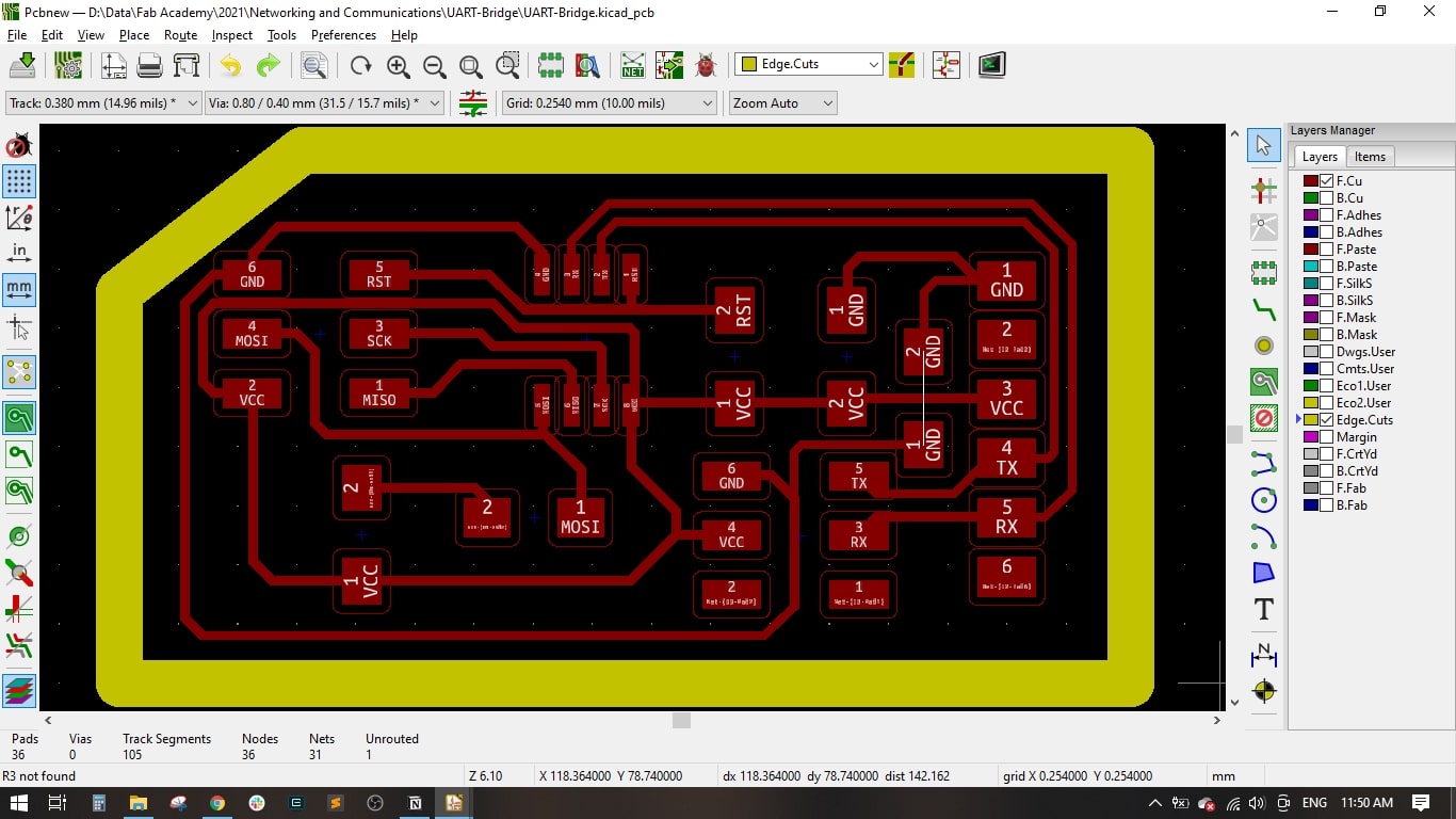
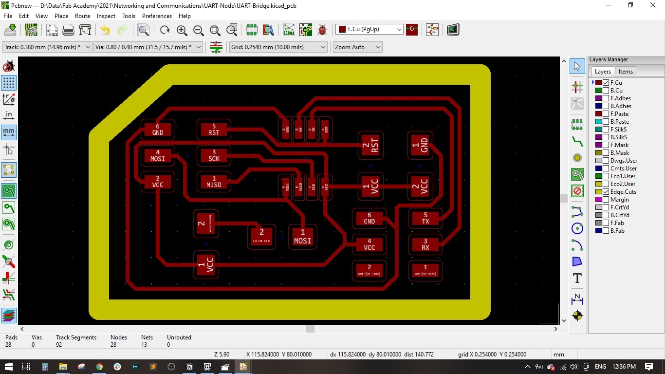
- In the PCB Layout, I routed all the traces on the top layer and drawed the board outline.
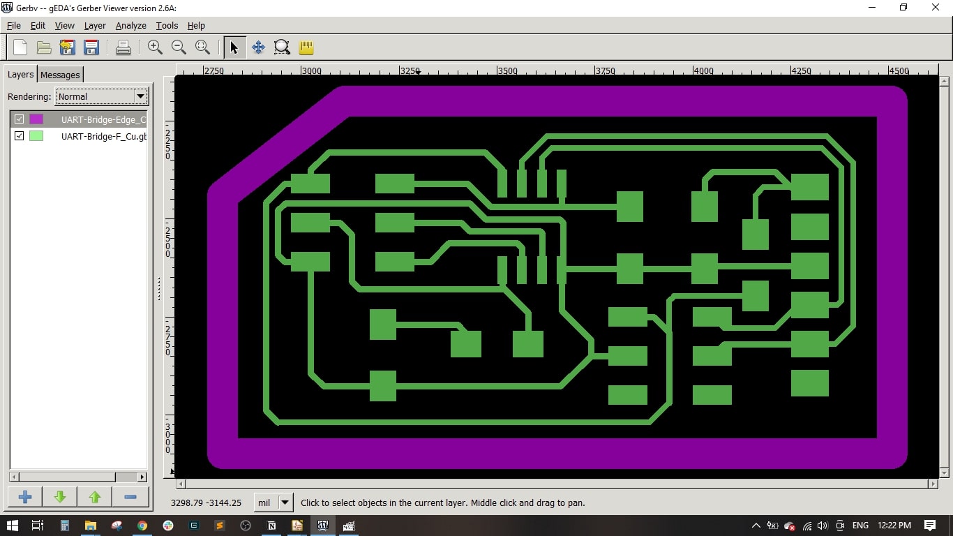
- Finally, I exported the Gerber files of the top and outline layers.
Step(2): Preparing the png files on Gerbv and GIMP
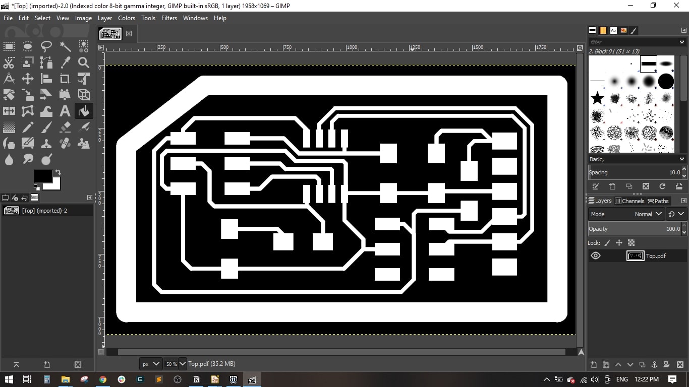
- I used Gerbv to export a .pdf file which includes the top layer and the outline in one file and in black color.
- Then, I used GIMP tp export .png file for the top (traces in White with black background) and .png file for the outline (Outline in Black with White background)
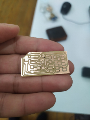
Step(3): PCB Fabrication, Assembly and Soldering
- I used the Fab Modules and the MonoFab milling machine to fabricate the PCB, we have learnt how to produce a PCB in the Electronics Production week.
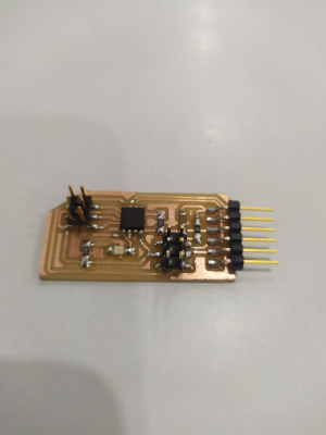
- I prepared the needed components as follows,
- I soldered all the components from the centre to outside.
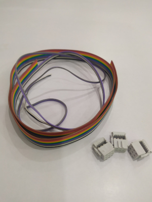
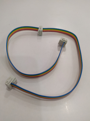
- I used the Ribbon cable and made 3 connectors to connect the bridge with the 2 nodes.
| Component | Description | QTY |
|---|---|---|
| ATTINY45 | IC AVR MCU 4K 10MHZ 8SOIC- | 3 |
| 609-5161-1-ND | 6 Positions Header Connector 0.100" SMD | 6 |
| 311-10.0KFRCT-ND | RES 10.0K OHM 1-4W 1% 1206 SMD | 3 |
| 311-499FRCT-ND | RES 499 OHM 1-4W 1% 1206 SMD | 3 |
| 311-0FRCT-ND | RES 0 OHM 1-4W 1% 1206 SMD | 1 |
| 445-1423-1-ND | CAP CER 1UF 50V X7R 10% 1206- | 3 |
Step(4): Circuit Programming and Testing
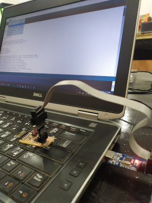
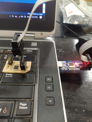
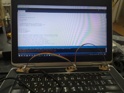
- I used the USBasp to program the circuits, I conncted it through the ISP connector.
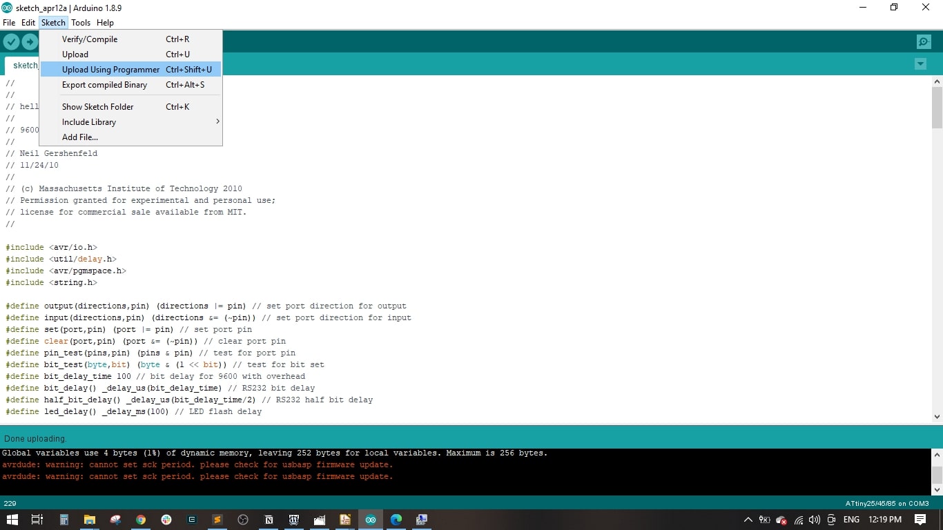
- Uploaded the code in Arduino IDE and did the compiling
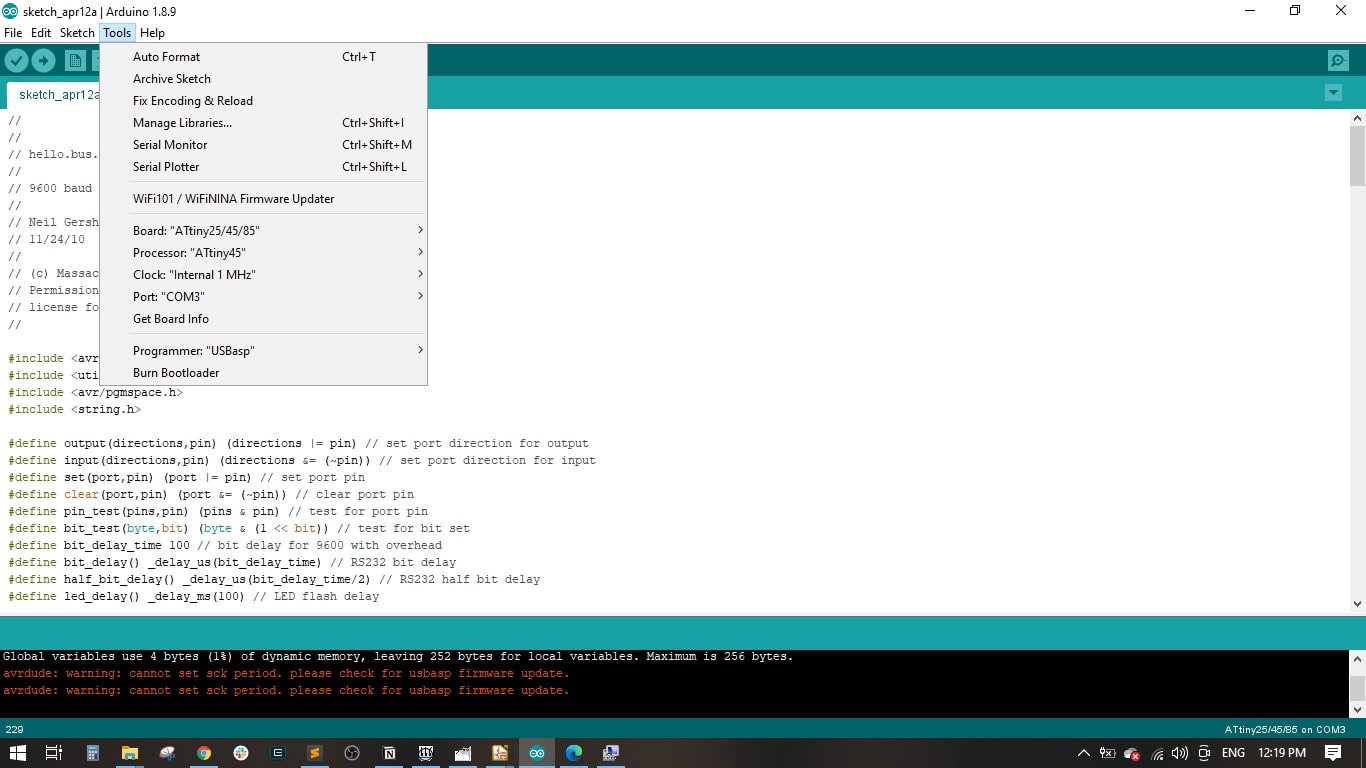
- It is important to make sure we select the ATtiny 45 as Board and processor, Internal 1 MHz Clock and the USBasp as programmer.
- I uploaded the code to the board by using the "Upload Using Programmer"
- I connected the bridge with the nodes through the Ribbon cable.
Group Assignment
Ways of Communications
Introduction
Embedded electronics is all about interlinking circuits (processors or other integrated circuits) to create a symbiotic system. In order for those individual circuits to swap their information, they must share a common communication protocol. Hundreds of communication protocols have been defined to achieve this data exchange, and, in general, each can be separated into one of two categories: parallel or serial.
Parallel vs. Serial
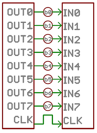
Parallel interfaces transfer multiple bits at the same time. They usually require buses of data - transmitting across eight, sixteen, or more wires. Data is transferred in huge, crashing waves of 1's and 0's.
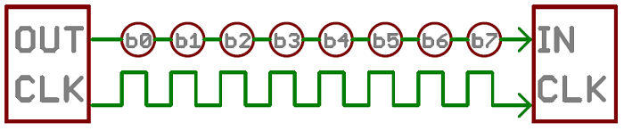
Serial interfaces stream their data, one single bit at a time. These interfaces can operate on as little as one wire, usually never more than four.
Parallel communication certainly has its benefits. It's fast, straightforward, and relatively easy to implement. But it requires many more input/output (I/O) lines. If you've ever had to move a project from a basic Arduino Uno to a Mega, you know that the I/O lines on a microprocessor can be precious and few. So, we often opt for serial communication, sacrificing potential speed for pin real estate.
Asynchronous Serial
Asynchronous means that data is transferred without support from an external clock signal. This transmission method is perfect for minimizing the required wires and I/O pins, but it does mean we need to put some extra effort into reliably transferring and receiving data.
The asynchronous serial protocol has a number of built-in rules - mechanisms that help ensure robust and error-free data transfers, such as:
- Baud rate: This specifies how fast data is being sent over the serial line, usually expressed as bits-per-second (bps). Inverting the bps tells you how long it takes to transmit a single bit. I’ve generally been using a baud rate of 9600, because speed wasn’t critical. The highest speed generally is 115200, however the chance for errors gets greater the faster you’re sending.
- Synchronization bits: These are the start and stop bits, which mark the beginning and end of a packet, which is (usually) a byte of data. A serial line idles in HIGH, meaning when nothing is being sent it is held at the value 1. The start bit will transform the line from 1 to 0, while a stop bit will move it back by holding the line at 1 again.
- Data bits: This is the real information that the processor wants to send. It’s generally called a data chunk because the exact size (in bits) isn’t fixed, it can be anything from 5 to 9 bits, but the standard is 8 bits.
- Parity bits: Parity is a form of very simple, low-level error checking. It comes in two flavors: odd or even. To produce the parity bit, all 5-9 bits of the data byte are added up, and the evenness of the sum decides whether the bit is set or not. For example, assuming parity is set to even and was being added to a data byte like 0b01011101, which has an odd number of 1's (5), the parity bit would be set to 1. Conversely, if the parity mode was set to odd, the parity bit would be 0. Parity is optional, and not very widely used. It can be helpful for transmitting across noisy mediums, but it'll also slow down your data transfer a bit and requires both sender and receiver to implement error-handling (usually, received data that fails must be re-sent).
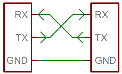
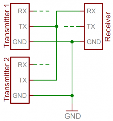
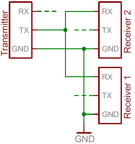
Wiring and Hardware: A serial bus consists of just two wires - one for sending data and another for receiving. As such, serial devices should have two serial pins: the receiver, RX, and the transmitter, TX.
It's important to note that those RX and TX labels are with respect to the device itself. So the RX from one device should go to the TX of the other, and vice-versa. It's weird if you're used to hooking up VCC to VCC, GND to GND, MOSI to MOSI, etc., but it makes sense if you think about it. The transmitter should be talking to the receiver, not to another transmitter.
UARTs
- A universal asynchronous receiver/transmitter (UART) is a block of circuitry responsible for implementing serial communication. Essentially, the UART acts as an intermediary between parallel and serial interfaces. On one end of the UART is a bus of eight-or-so data lines (plus some control pins), on the other is the two serial wires - RX and TX.
- You can also use software to turn any GPIO port into a TX or RX port, such as the SoftwareSerial library in the Arduino IDE. However, this takes up both memory and computing time, so should only be done if the processor doesn’t have a UART already (or you need more TX and RX ports).
- The downside of using serial communication is that there’s extra overhead in the extra start and stop bits (and possible parity bit), and it apparently requires complex hardware. Furthermore, it’s really only designed to communicate between two devices. If more than two devices are connected, you could get issues where two of them are trying to transmit at the exact same time, resulting in a conflict on the line.
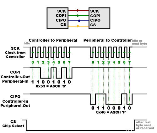
Serial Peripheral Interface (SPI)
- is an interface bus commonly used to send data between microcontrollers and small peripherals such as shift registers, sensors, and SD cards. It uses separate clock and data lines, along with a select line to choose the device you wish to talk to.
- The start of a frame comes from a change in the line, from 0 to 1 or vice versa. It depends on the exact device what it sees as idle. The receiver will merely listen for an edge, a change from the idle state.
- With SPI only one processor will generate the clock signal, this is the Master, while all devices/peripherals at the other side are the Slave. Data that is being send from the Master to a Slave member is send along the MOSI line, Master Out / Slave in. When the Slave wants to send something back, it comes along the MISO line, Master In / Slave Out.
- For sending back a large amount of data from the Slave to the Master, you might need to use the first frame to tell the Master how many clock cycles it should generate to get it all, but this is a more advanced thing I believe.
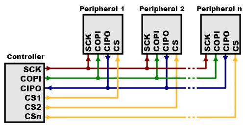
- The last of the lines with SPI is the SS or Slave Select. This is the MMaster’s way of saying which Slave member should start listening when it sends data across the MOSI line. Generally the SS line is idle as HIGH. Just before data is sent to the Slave member, the line is brought low, which activates it. When the Master is done, the SS line is made high again.
- To add multiple slaves, each will generally get its own SS line. To talk to a particular slave, you’ll make their SS line low and keep the other SS lines high.
- Advantages of SPI:
- It's faster than asynchronous serial.
- The receive hardware can be a simple shift register.
- It supports multiple peripherals.
-
Disadvantages of SPI:
- It requires more signal lines (wires) than other communications methods.
- The communications must be well-defined in advance (you can't send random amounts of data whenever you want)
- The controller must control all communications (peripherals can't talk directly to each other).
- It usually requires separate CS lines to each peripheral, which can be problematic if numerous peripherals are needed.
Inter-Integrated Circuit (I2C)
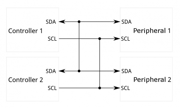
- is a protocol intended to allow multiple "peripheral" digital integrated circuits ("chips") to communicate with one or more "controller" chips. Like the Serial Peripheral Interface (SPI), it is only intended for short distance communications within a single device. Like Asynchronous Serial Interfaces (such as RS-232 or UARTs), it only requires two signal wires to exchange information.
- I2C requires a mere two wires, like asynchronous serial, but those two wires can support up to 1008 peripheral devices. Also, unlike SPI, I2C can support a multi-controller system, allowing more than one controller to communicate with all peripheral devices on the bus (although the controller devices can't talk to each other over the bus and must take turns using the bus lines).
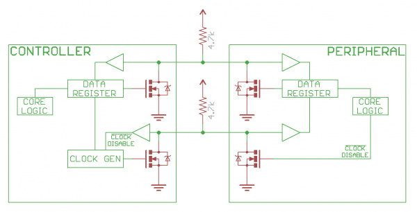
- Data rates fall between asynchronous serial and SPI; most I2C devices can communicate at 100kHz or 400kHz. There is some overhead with I2C; for every 8 bits of data to be sent, one extra bit of meta data (the "ACK/NACK" bit, which we'll discuss later) must be transmitted. The hardware required to implement I2C is more complex than SPI, but less than asynchronous serial. It can be fairly trivially implemented in software.
- Within the I2C protocol messages are split into two types of frames:
- Address frame, In this frame the Controller will indicate which Peripheral member it wants to send data to. It is always the first frame in any new communication sequence.
- Data frame(s), These 8-bit frames contain the data being send. This is send along the SDA line by either the controller or the Peripheral, depending on whether the R/W bit in the address frame said it should be read or write.
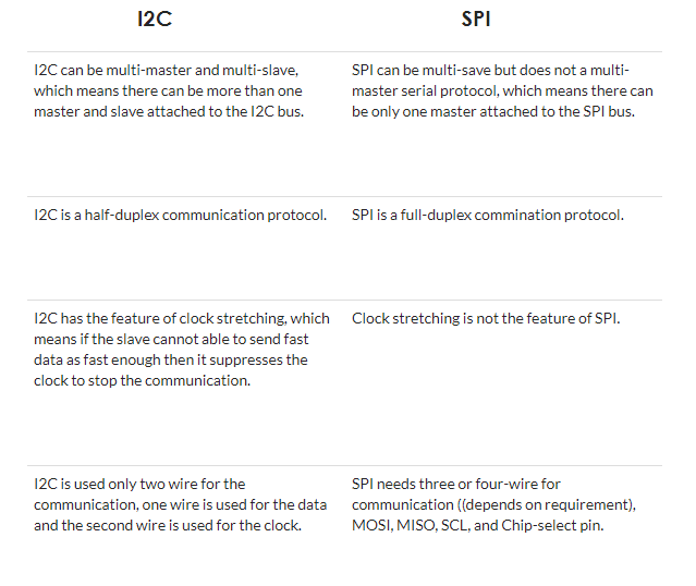
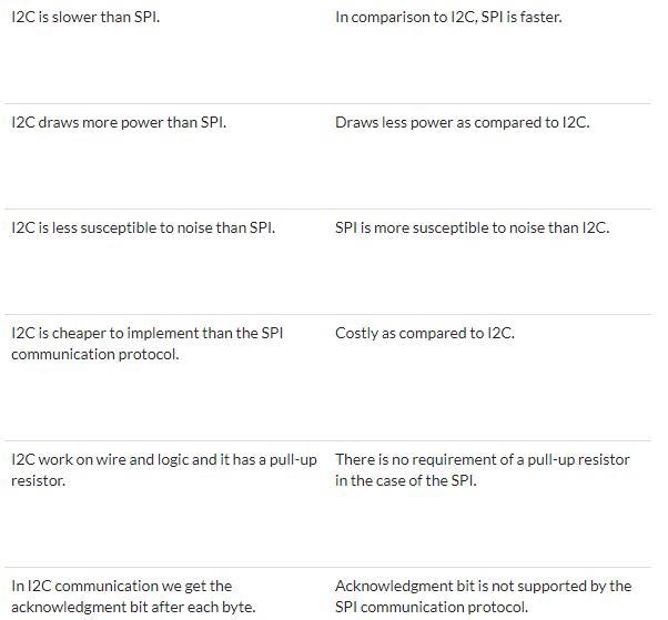
I2C vs SPI
Implementation
Introduction
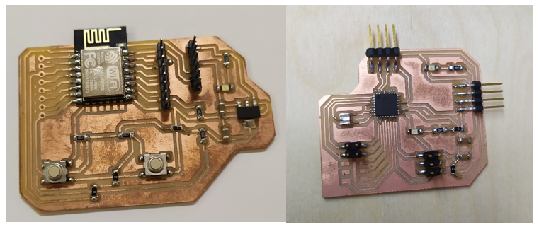
- For the group assignment, it is required to send a message between two project/boards. I prefered to use my produced boards of the final project to implement this task.
- The first board is the WIFI Board, it inclues the ESP8266 with a Reset and a Flashing buttons and FTDI pins for serial programming.
- The second board is the Controller Board, it includes the ATMega 328p along with spi pins and I/O pins.
Programming the WIFI Board
// Including Libraries
#define DEBUG 1
#include
#include
#include


//FIXED WIFI Settings
#define ssid      "Orange-D955"       // WiFi SSID
#define password  "IloveFLE"  // WiFi password


// FIXED IP and NETWORK SETTINGS
IPAddress ip(192, 168, 1, 104);
//set static ip
IPAddress gateway(192, 168, 0, 1);
//set gateway
IPAddress subnet(255, 255, 255, 0);
//set subnet
ESP8266WebServer server ( 80 );


// INVENTORY ITEM NAMES, COUNT and QUANTITY
#define numberOfItems 12
String item[numberOfItems] = {
  "ATtiny44",
    "ATtiny45",
    "20MHz_Oscillator",
    "10k_Resistor",
    "499_Resistor",
    "LED_Red",
    "LED_Blue",
    "ATMega328p",
    "1uF_Capacitor",
    "Push_Buttons",
    "AVR_ISP_Header",
    "Male_Header_Pins"
}
;
byte itemQty[numberOfItems]  = {
  0,0,0,0,0,0,0,0,0,0,0,0
}; // DUMMY VARIABLE for storage
byte itemQtyS[numberOfItems] = {
  10,13,5,18,6,9,3,2,12,14,16,20
}; // INITIAL COUNT when there is nothing in EEPROM, this is already saved now


// WEBPAGE CODE
// code was tested with notepad and browser(chrome)
// code written with help from bootstrap online demos and tutorials
// once code was ready, changed all double quotes to single quotes
// added variables for dynamic web page generation
String getPage(int boxNumber) {
  String page = "< html lang='en'>";
  page += "< html lang='en'>";
  page += "< head>";
  page += "< meta charset='utf-8'>";
  page += "< meta http-equiv='X-UA-Compatible' content='IE=edge'>";
  page += "< meta name='viewport' content='width=device-width, initial-scale=1'>";
  page += "< title>Smart Drawer< /title>";
  page += "< meta name='author' content='LayoutIt!'>";
  page += "< link rel='stylesheet' href='https://maxcdn.bootstrapcdn.com/bootstrap/3.3.7/css/bootstrap.min.css'>";
  page += "< script src='https://ajax.googleapis.com/ajax/libs/jquery/3.3.1/jquery.min.js'>< /script>";
  page += "< script src='https://maxcdn.bootstrapcdn.com/bootstrap/3.3.7/js/bootstrap.min.js'>< /script>";
  page += "";
  page += " < body>";
  page += "< div class='container-fluid'>";
  page += "  < div class='row'>";
  page += "   < div class='col-md-12'>";
  page += "     < p>";
  page += "     < /p>";
  page += "   < /div>";
  page += " < /div>";
  page += " < div class='row'>";
  page += "   < div class='col-md-12'>";
  page += "     < div class='jumbotron'>";
  page += "       < h2>";
  page += "       Smart Drawer< /h2>";
  page += "       < h3>";
  page += "       Find and store components smartly< /h3>";
  page += "       < p>";
  page += "          Please type the component name in the below box";
  page += "       < /p>";
  // SERACH BOX CODE - now removed.
  //page += "        < p>";
  //page += "         < form role='form' action='/' method='POST' class='form-inline'>";
  //page += "           < div class='form-group'>";
  //page += "             < label for='componentLabel'>";
  //page += "             SEARCH HERE: < /label>";
  //page += "             < input class='form-control' id='componentLabel' name='searchText'>";
  //page += "           < /div>";
  //page += "           < button type='submit' class='btn btn-primary'>";
  //page += "           Submit < /button>";
  //page += "         < /form>";
  //page += "       < /p>";
  page += "       < div class='row' style='margin-bottom:15px;'>";
    page += "         < form role='form' action='/' method='POST' class='form-inline'>";
    page += "           < div class='form-group'>";
    page += "             < label>Component Name:< /label>";
    page += "             < input type='text' id='search' name='search'>";
    page += "           < /div>";
    page += "         < button type='submit' class='btn btn-primary'>Search< /button>";
    page += "         < /form>";

  if(boxNumber != -1)
  {
    page += "< div class='col-sm-4'>";
    page += "< button type='button' class='btn btn-block btn-primary btn-lg' data-toggle='modal' data-target='#";
    page += item[boxNumber];
    page += "'>";
    page += item[boxNumber];
    page += " - Qty: ";
    page += String(int(itemQty[boxNumber]));
    page += "< /button>< /div>";

    // Loop to generate code for MODAL/POPUP Boxes that appear when any button is clicked
    // Generated DYNAMICALLY from variables in code
      page += "< div id='";
      page += item[boxNumber];
      page += "' class='modal fade' role='dialog'>";
      page += "  < div class='modal-dialog'>";
      page += "    < div class='modal-content'>";
      page += "      < div class='modal-header'>";
    page += "        < button type='button' class='close' data-dismiss='modal'>×";
    page += "        < h4 class='modal-title'>";
    page += item[boxNumber];
    page += "< /h4>";
    page += "      < /div>";
    page += "      < div class='modal-body'>";
    page += "        < p>The Quantity of this item is = ";
    page += String(int(itemQty[boxNumber]));
    page += "        < /p>";
    page += "       < p>";

    page += "         < form role='form' action='/' method='POST' class='form-inline'>";
    page += "           < div class='form-group'>";
    page += "             < label>Enter Quantity:";
    page += "             < input type='number' class='form-control bfh-number' data-zeros='true' value='0' name='qtyChange' />";
    page += "             < label class='radio-inline'>< input type='radio' name='add'>ADD< /label>";
    page += "             < label class='radio-inline'>< input type='radio' name='remove'>REMOVE";
    page += "             < input type='hidden' name='itemNumber' value='";
    page += String(boxNumber);
    page += "             '/>";
    page += "           < /div>";
    page += "         < button type='submit' class='btn btn-primary'>LOCATE COMPONENT";
    page += "         < /form>";
    page += "        < /p>";
    page += "      < /div>";
    page += "    < /div>";
    page += "  < /div>";
    page += "< /div>";
  }
  page += "     < /div>";
  page += "   < /div>";
  page += " < /div>";
  page += "< /div>";
  page += "< /body>";
  page += "< /html>";
  return page;
}

// function which manages how the page is shown to user and what operation is perfomed for inventory control.
void handleRoot() {
  int itemNumber = 100, qtyChange = 0, sign = 1;
  String search_value = "";
  boolean search_v = false;
  int search_index = -1;
  if (server.args() > 0 ) {
    if(DEBUG)
      Serial.println("Server Arguments: ");
    for ( int i = 0; i < server.args(); i++ ) {
      if(DEBUG){
        Serial.print(server.argName(i));
        Serial.print(": ");
        Serial.println(server.arg(i));
      }
      if (server.argName(i) == "search")
      {
                search_value = server.arg(i);
                search_v = true;
      }
      if (server.argName(i) == "qtyChange")
                qtyChange = server.arg(i).toInt();
      if (server.argName(i) == "itemNumber")
                itemNumber = server.arg(i).toInt();
      if (server.argName(i) == "add")
                sign = 1;
      if (server.argName(i) == "remove")
                sign = -1;
      // if server argument is a valid add/remove number
      // the item quantity is changed, saved in variable, showed to user and saved in EEPROM
      if(itemNumber < numberOfItems) {
        if(itemQty[itemNumber]+(qtyChange*sign)>=0){
          itemQty[itemNumber] = itemQty[itemNumber]+(qtyChange*sign);
          EEPROM.write(itemNumber, itemQty[itemNumber]);
          EEPROM.commit();
        }
        Serial.println(itemNumber);
        Serial.println(",");
      }
    }
  }
  if(search_v)
  {
    for (int z=0; z< numberOfItems; z++)
    {
      if(search_value == item[z])
      {
        search_index = z;
        break;
      }
    }

  server.send ( 200, "text/html", getPage(search_index));

  }
  else
    server.send ( 200, "text/html", getPage(-1) );
}

int address = 0;
byte value;
void setup() {
    // INITIALIZATION CODE, Serial, EEPROM, Server
  delay(1000);
  EEPROM.begin(512);
  Serial.begin(115200);
  delay(1000);
  Serial.println(-1);
  delay(1000);
  Serial.println(-1);
  // WRITE ALL DEFAULT VALUES TO EEPROM
  //  Serial.println("itemQtyS[z]");
  //  for(int z=0; z< numberOfItems; z++){
  //    address = z;
  //    EEPROM.write(address, itemQtyS[z]);
  //    Serial.println(itemQtyS[z]);
  //    address  = address  + 1;
  //    if (address  == 512)
  //    {
  //      address  = 0;
  //      EEPROM.commit();
  //    }
  //  }
    // READ ITEM QUANTITY from EEPROM
  if(DEBUG)
    Serial.println("itemQtyREAD[z]");
  for (int z=0; z< numberOfItems; z++) {
    address = z;
    itemQty[z] = EEPROM.read(address);
    if(DEBUG)
      Serial.println(itemQty[z]);
    address  = address  + 1;
    if (address  == 512) {
      address  = 0;
      EEPROM.commit();
    }
  }


// connect to WIFI and start WEB SERVER
  if(DEBUG) {
    Serial.println();
    Serial.println();
    Serial.print("Connecting to ");
    Serial.println(ssid);
  }
  WiFi.config(ip, gateway, subnet);
  WiFi.begin(ssid, password);
  while (WiFi.status() != WL_CONNECTED) {
    delay(500);
    if(DEBUG)
          Serial.print(".");
  }
  if(DEBUG) {
    Serial.println("");
    Serial.println("WiFi connected");
  }
  delay(1000);
  Serial.println(0);
  server.begin();
  if(DEBUG) {
    Serial.println("Server started");
    Serial.print("Type this address in URL to connect: ");
    Serial.print("http://");
    Serial.println(ip);
    Serial.println("/");
  }


  // link to the function that manage launch page
  server.on ( "/", handleRoot );
  server.begin();
  delay(1000);
  Serial.println(1);
  if(DEBUG)
    Serial.println ( "HTTP server started" );
  delay(1000);
  Serial.println(2);
  delay(1000);
  Serial.println(-1);
  delay(1000);
  Serial.println(-1);


  // TURN OFF ALL LEDS
  // at start LEDs of boxes 1, 2 and 3 are turned on to indicate system status
  // each step makes the other box LEDs turn on
  // box 2 is wifi connected status
  // box 3 is server start status
}
void loop() {
  server.handleClient();
  delay(500);
}

// LOOP code, keeps running forever.


// Original checked by Noor
// edited by Mahmoud Abo Elnaga
Programming the Controller Board
// Including Libraries
#include "FastLED.h"
#define NUM_LEDS 20
CRGB leds[NUM_LEDS];
#define PIN 6


// variable for which BOX LEDs to blink
byte ledToBlink = 0;


void setup()
{
  Serial.begin(115200);
  FastLED.addLeds(leds, NUM_LEDS).setCorrection( TypicalLEDStrip );
}
//Initialization PART.
// Starts the Serial Port, Controller waits for a NUMBER on the Serial Port to turn on the relevant LEDs of the selected BOX.


// RGB LED SUPPORT FUNCTIONS - from blog link: https://www.tweaking4all.com/hardware/arduino/adruino-led-strip-effects/
void showStrip() {
 #ifdef ADAFRUIT_NEOPIXEL_H
   // NeoPixel
   strip.show();
 #endif
 #ifndef ADAFRUIT_NEOPIXEL_H
   // FastLED
   FastLED.show();
 #endif
}


// RGB LED SUPPORT FUNCTIONS - for a single PIXEL - from blog link: https://www.tweaking4all.com/hardware/arduino/adruino-led-strip-effects/
void setPixel(int Pixel, byte red, byte green, byte blue) {
 #ifdef ADAFRUIT_NEOPIXEL_H
    // NeoPixel
   strip.setPixelColor(Pixel, strip.Color(red, green, blue));
 #endif
 #ifndef ADAFRUIT_NEOPIXEL_H
   // FastLED
   leds[Pixel].r = red;
   leds[Pixel].g = green;
   leds[Pixel].b = blue;
 #endif
}


// RGB LED SUPPORT FUNCTIONS - for all LEDs - from blog link: https://www.tweaking4all.com/hardware/arduino/adruino-led-strip-effects/
void setAll(byte red, byte green, byte blue) {
  for(int i = 0; i < NUM_LEDS; i++ ) {
    setPixel(i, red, green, blue);
  }
  showStrip();
}


// LED EFFECT FUNCTION - from blog link: https://www.tweaking4all.com/hardware/arduino/adruino-led-strip-effects/
// MODIFIED to read SERIAL and ONLY show the relevant LED and the one before and after it.
// Each box has 3 LEDs, so the number received is multiplied by 3 and then the LED before it and after it is illuminated and rest are all set as color to BLACK.
void RunningLights(byte red, byte green, byte blue, int WaveDelay) {
  int Position=0;
  for(int i=0; i0){
          // ONLY TURN ON 3 LEDs and rest all set to BLACK==OFF
          //if(i==ledToBlink-3 || i==ledToBlink-2 || i==ledToBlink-1)
          if( i==ledToBlink-1 )
           setPixel(i,((sin(i+Position) * 127 + 128)/255)*red,
           ((sin(i+Position) * 127 + 128)/255)*green,
           ((sin(i+Position) * 127 + 128)/255)*blue);
          else
            leds[i] = CRGB::Black;
        }else{
            leds[i] = CRGB::Black;
        }
      }
      // CODE MODIFICATION END

      showStrip();
      delay(WaveDelay);
  }
}

// LOOP FUNCTION, keeps the led effect running at all times
// LED effect changes color.
void loop() {
  RunningLights(0xff,0,0, 50);        // red
  RunningLights(0,0xff,0, 50);        // green
  RunningLights(0,0,0xff, 50);        // blue
  RunningLights(0xff,0xff,0xff, 50);  // white
  // original checked by Noor
  // further edits by Mahmoud Abo Elnaga
}
Wiring
- I connected the TX of the WIFI board to the RX of the Controller board.
- Connected the VCC and GND of the WIFI board to the VCC and GND of the Controller board. Both are operated at 5 VDC.
- Connected the addressable pin of the RGB led with Pin#6 of the controller board.
- Powered up the boards with 5 VDC and the RGB LED Strip with 12 VDC.
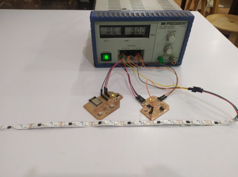
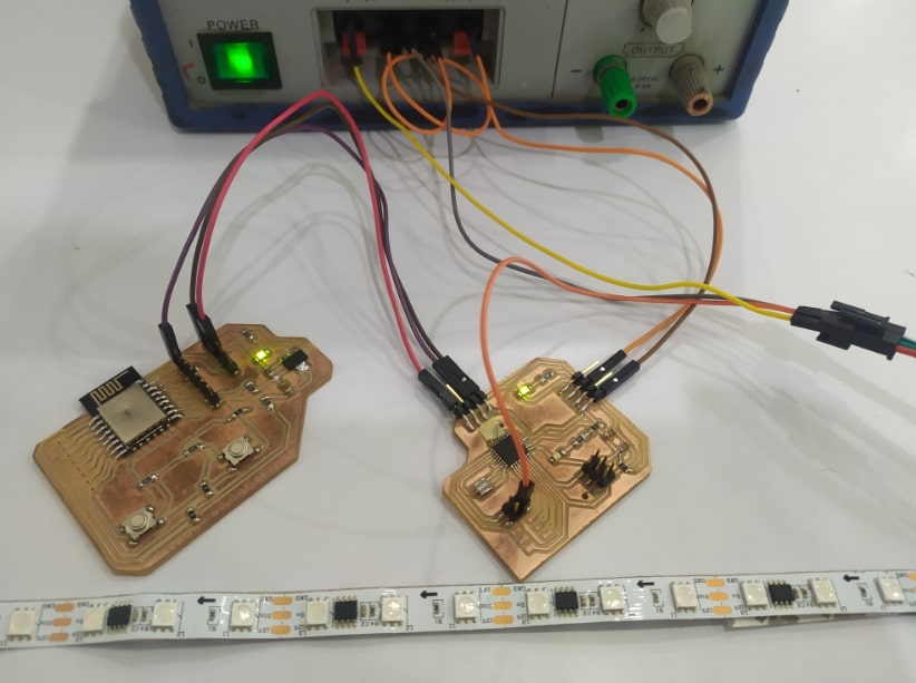
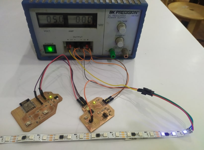
Results
- I connected the boards with the RGB LED Strip in the structure.
- Opened the IP address on my mobile phone and started typing the component name.
- Please note that Week 12, 13 and final project pages are integrating, they complete each other.