Measure the power consumption of an output device.
Document your work (in a group or individually)
Individual Assignment:
Add an output device to a microcontroller board you've designed and program it to do something
Learning Outcomes:
Demonstrate workflows used in controlling an output device(s) with MCU board you have designed.
Steps in General:
Step(1): Designing the circuit on KiCAD
Step(2): Preparing the png files on Gerbv and GIMP
Step(3): PCB Fabrication, Assembly and Soldering
Step(4): Circuit Programming and Testing
Introduction
In this week I decided to design a board to control 2 servo motors, I did the Shematic and Layout in KiCAD and milled the PCB on the MonoFab SRM-20 Milling machine, soldered the components, programmed it and connected the Servo motors and finally powered the board with 12 VDC.
Steps in Details:
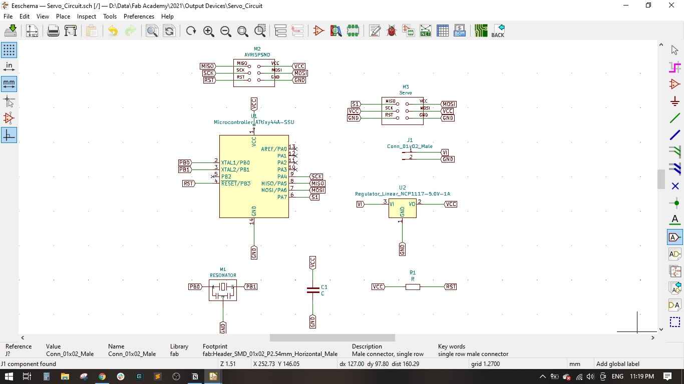
Step(1): Designing the circuit on KiCAD
I imported the components into the KiCAD Shematic and did the wiring as shown
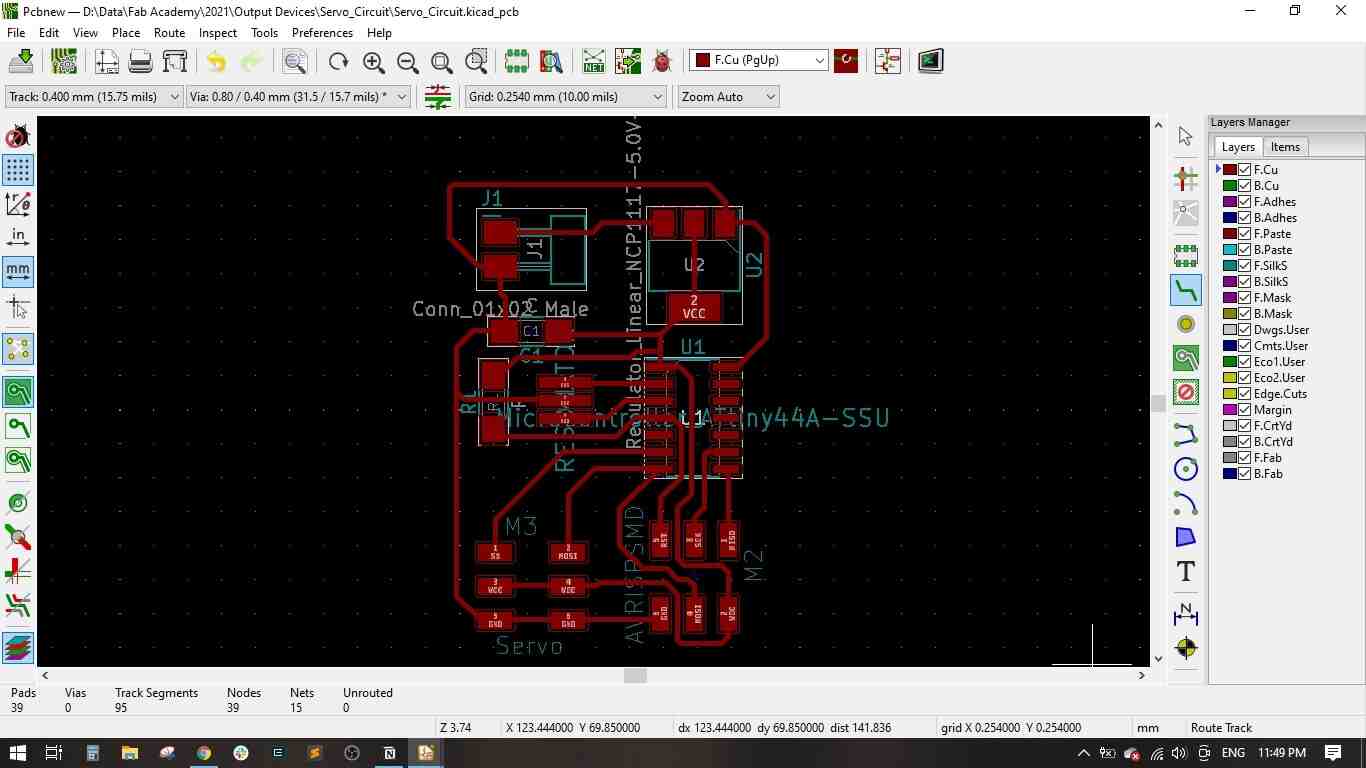
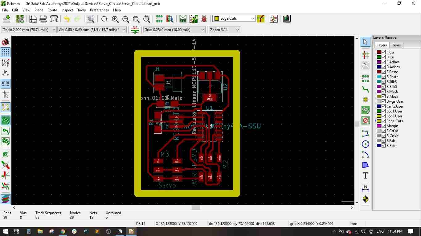
In the PCB Layout, I routed all the traces on the top layer and drawed the board outline.
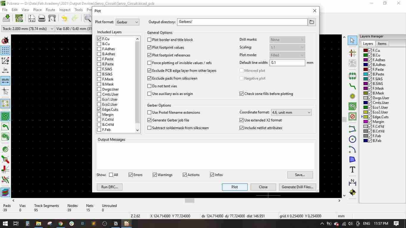
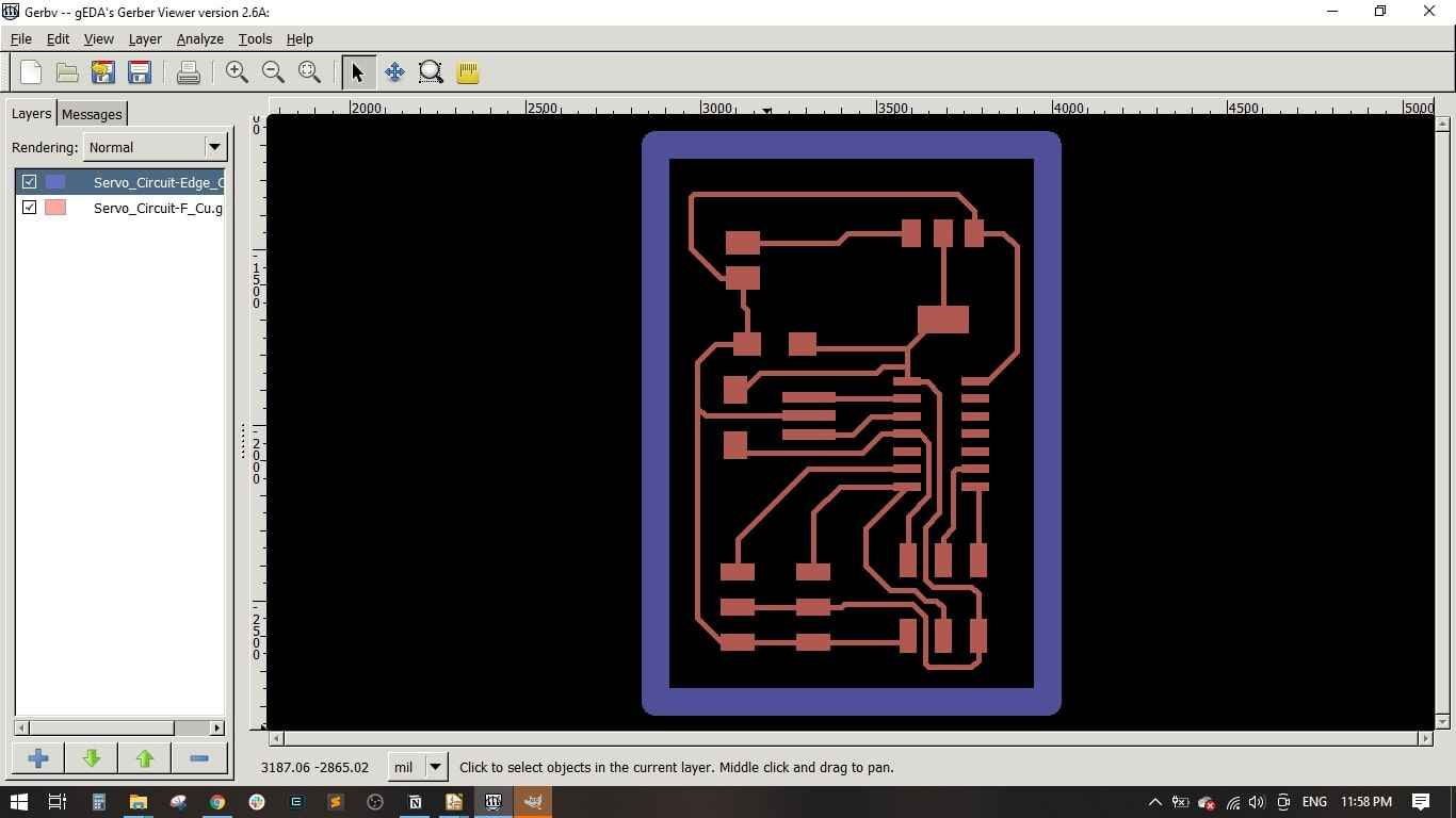
Finally, I exported the Gerber files of the top and outline layers.
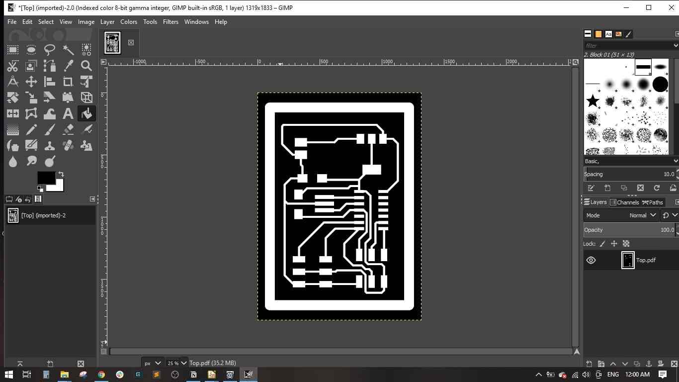
Step(2): Preparing the png files on Gerbv and GIMP
I used Gerbv to export a .pdf file which includes the top layer and the outline in one file and in black color.
Then, I used GIMP tp export .png file for the top (traces in White with black background) and .png file for the outline (Outline in Black with White background)
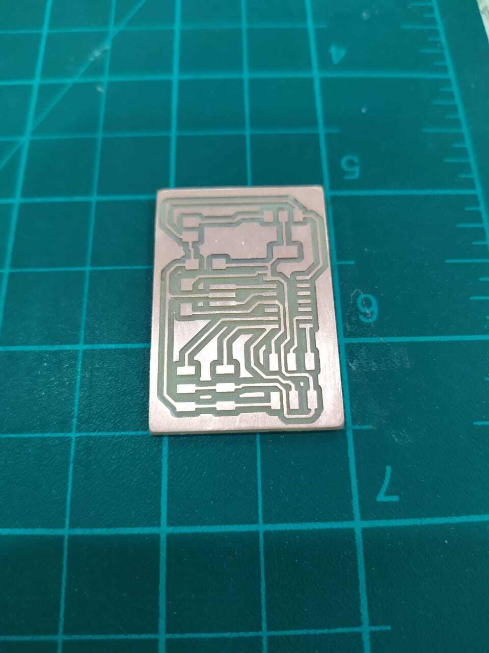
Step(3): PCB Fabrication, Assembly and Soldering
I used the Fab Modules and the MonoFab milling machine to fabricate the PCB, we have learnt how to produce a PCB in the Electronics Production week.
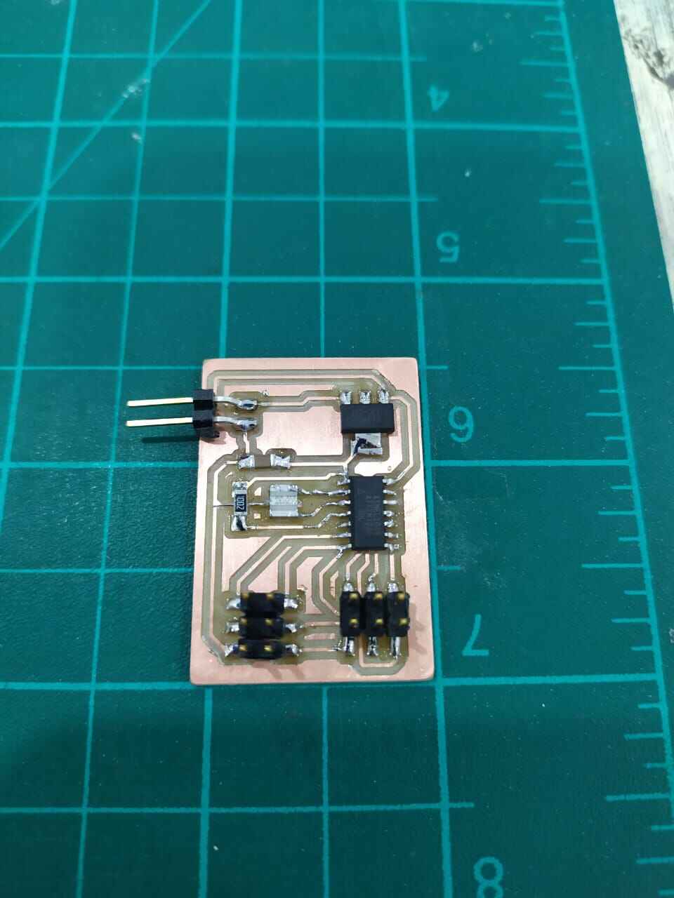
I prepared the needed components as follows,
Component
Description
QTY
ATTINY44A-SSU-ND
IC AVR MCU 4K 10MHZ 8SOIC-
1
ZLDO1117G50TA
Fixed LDO Voltage Regulator, Dropout, 5Vout and 1Aout.
1
609-5161-1-ND
6 Positions Header Connector 0.100" SMD
2
311-10.0KFRCT-ND
RES 10.0K OHM 1-4W 1% 1206 SMD
1
XC1109CT-ND
CER RESONATOR 20.00MHZ SMD
1
445-1423-1-ND
CAP CER 10UF 50V X7R 10% 1206-
1
2*1 Connector
Connector for powering the circuit
1
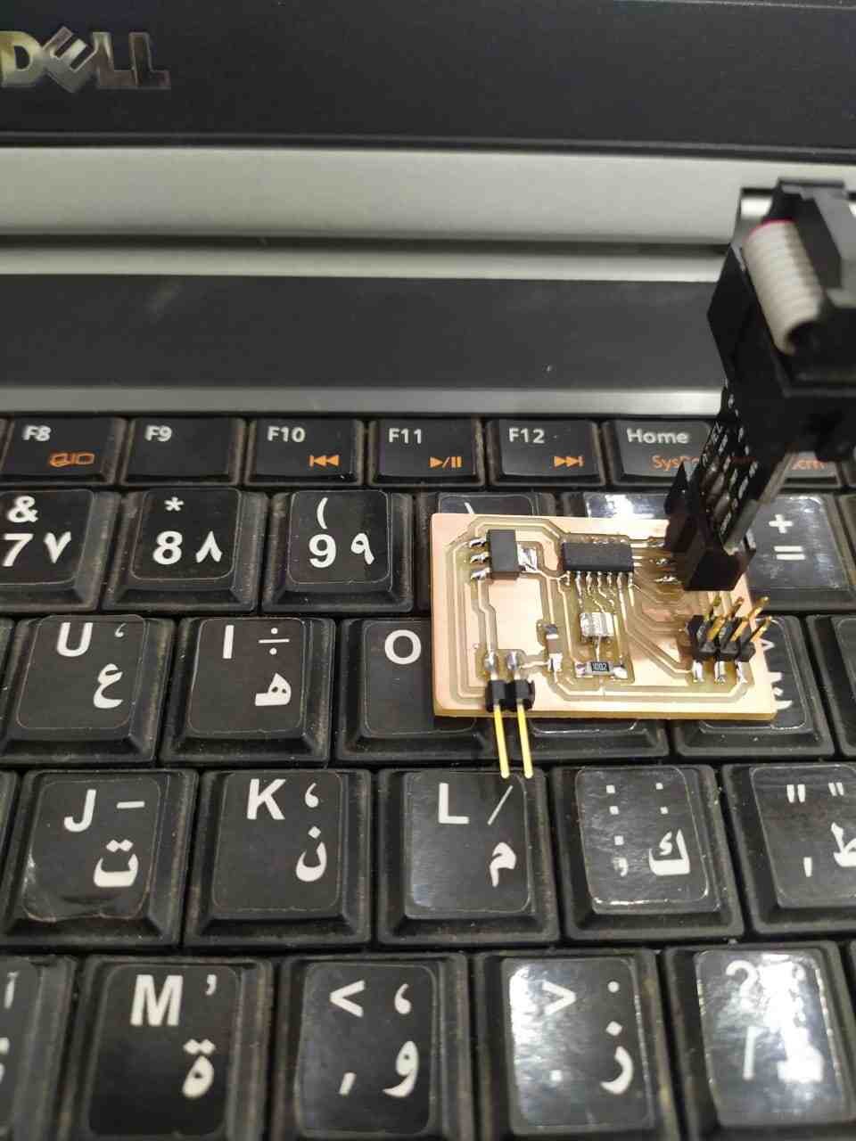
I soldered all the components from the centre to outside.
Step(4): Circuit Programming and Testing
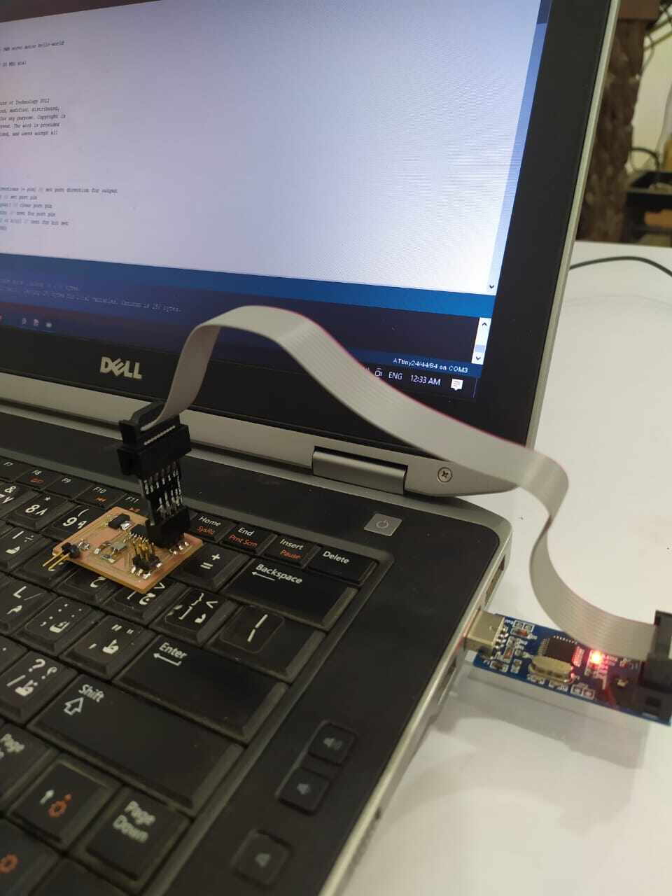
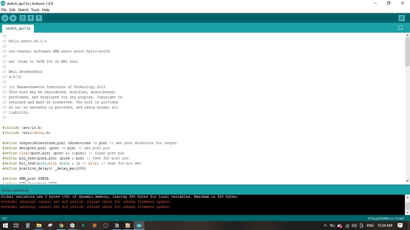
I used the USBasp to program the circuit, I conncted it through the ISP connector.
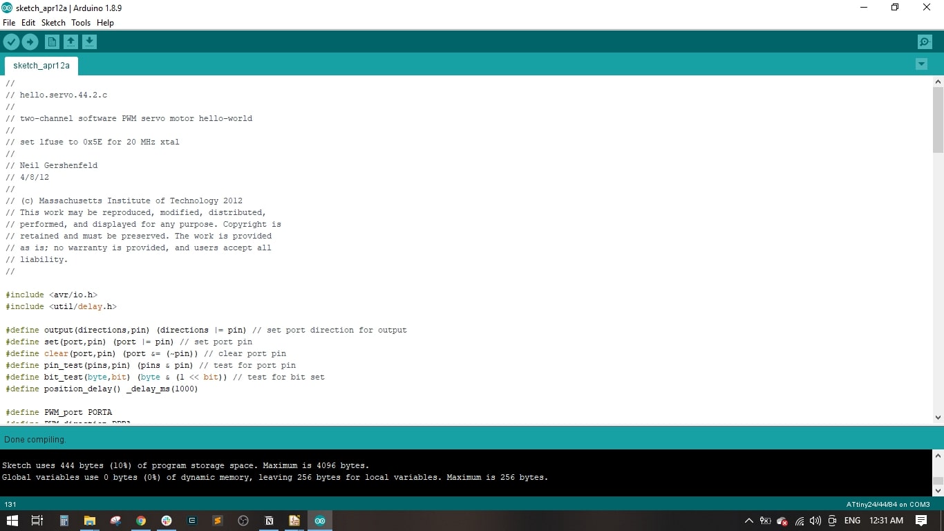
Uploaded the code in Arduino IDE and did the compiling
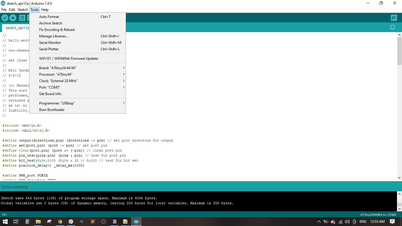
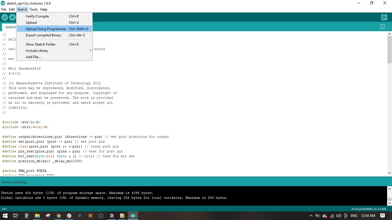
It is important to make sure we select the ATtin4 44 as Board and processor, External 20 MKz Clock and the USBasp as programmer.
I uploaded the code to the board by using the "Upload Using Programmer"
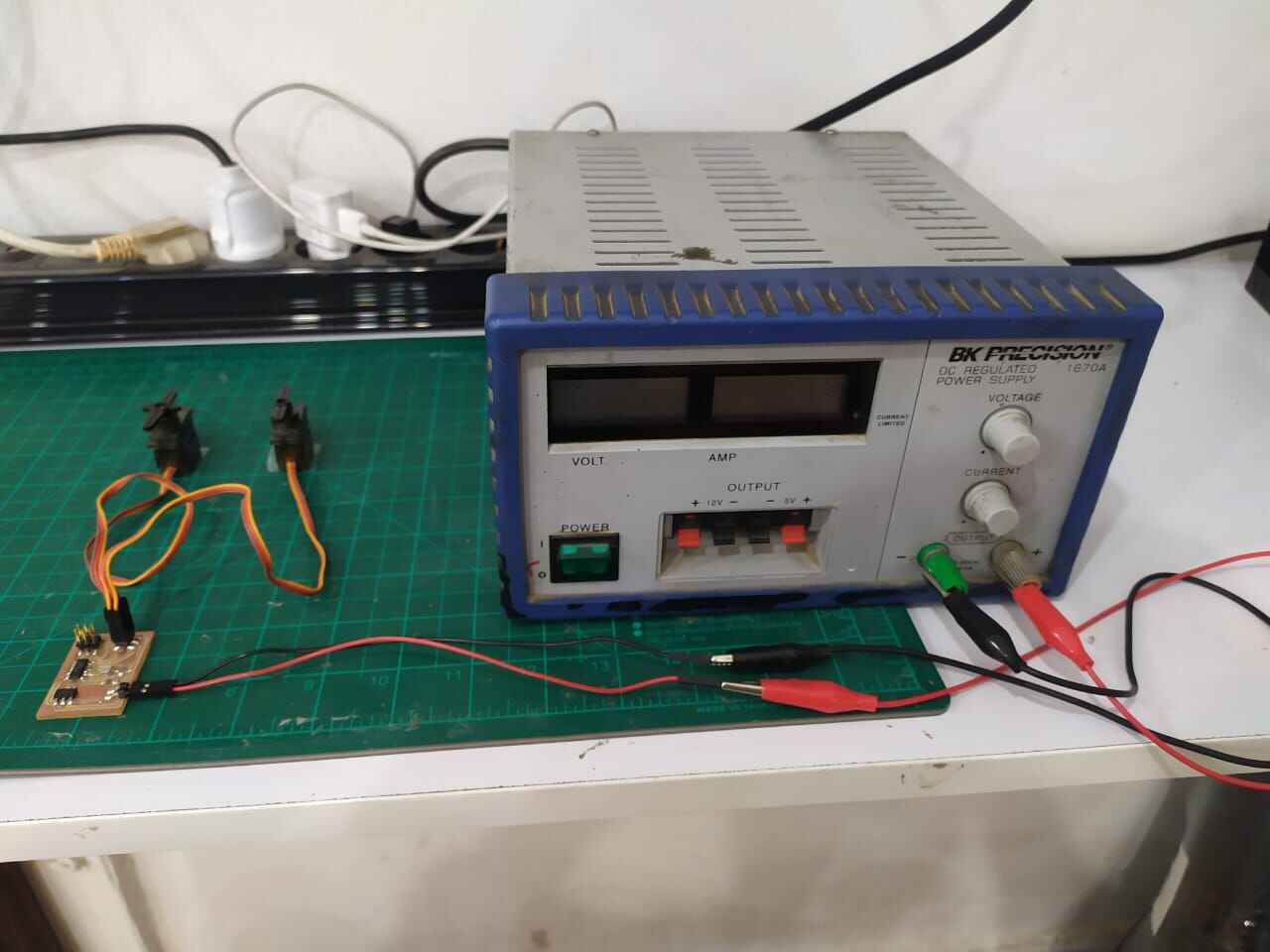
I connected 2 servo motors to the board and powered it by an external power supply with 12 VDC
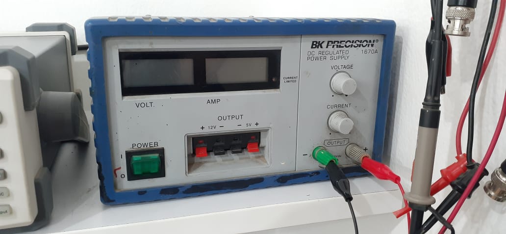
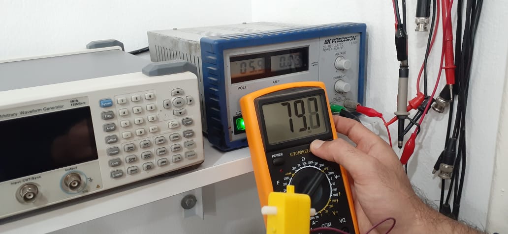
Group Assignment
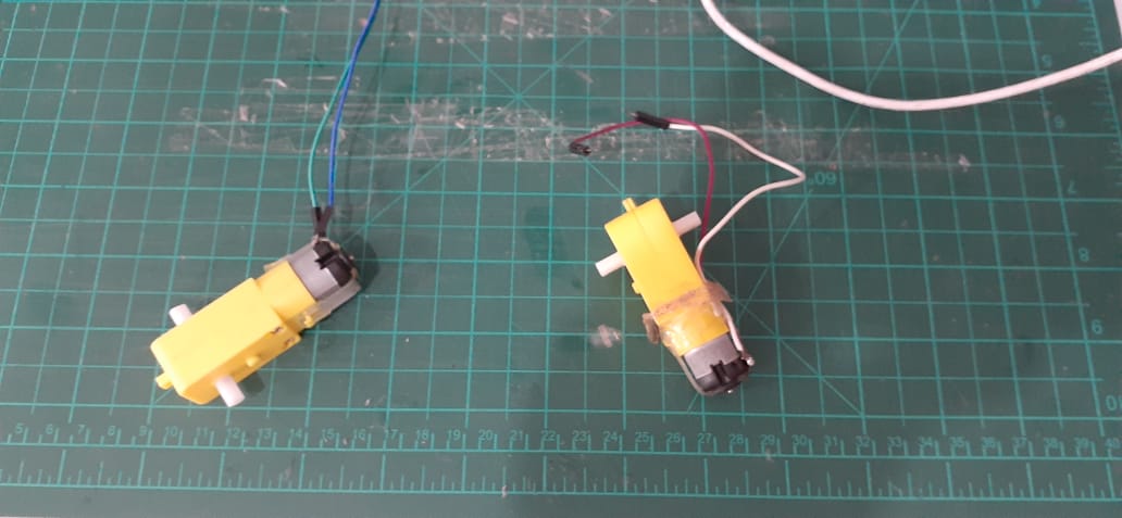
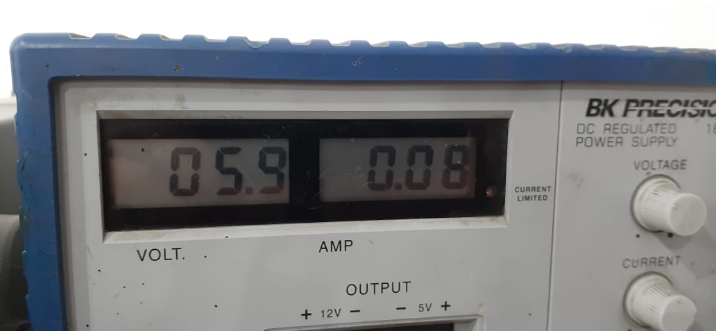
In this assignment we are going to measure the power of an output device which is a 6v DC motor using the regulated power supply readings and also using the multimeter.
It assumed 0.08 Ampere at the 6 Volt DC.
We know that Power = Volt * Ampere [P = V * I], so the consumed power will be 6 * 0.08 = 0.48 watt