The Plan
Part 1: Composites
Luciano offered to give us a demo of the process to make composites. I’m interested in composites but already had another project in mind. I offered to whip up a quick mold for us to form some composites for his demo. We decided to make a skateboard deck. It’s has smooth 3d curves would be easy to press the parts into with vacuum.
Part 2: Aluminum CNC Machining
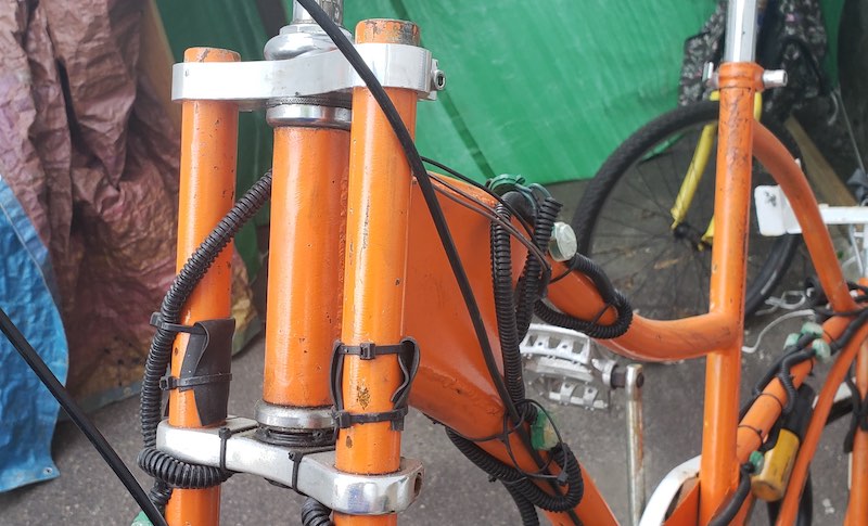
As soon I saw the Tormach PCNC 440 machine in the lab I knew I had a project for it. I’ve had a part on one of my bicycles that I’ve wanted to replace since I built it nearly 10 years ago. I had a triple clamp front fork that I pulled off a cheap mountain bike and modified it to fit my custom bike.
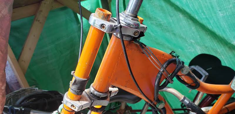
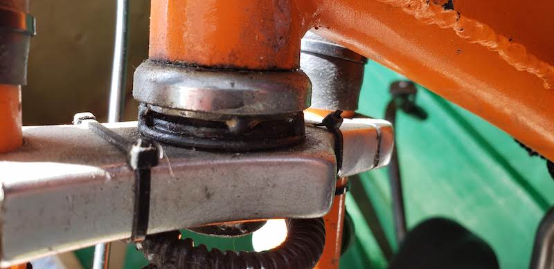
It works and has lasted longer than I expected but it wears out headset bearings faster than it should. This is because the alignment of the bearings isn’t quite straight because of how I had to modify it with the tools available at the time.
Now I plan to make fully custom clamps that hold the headset bearings correctly and fit onto the rest of the bike as is.
Composites Test Process
CAD
I found an excellent project called Open Source Skateboards which has a JSCAD script and a fusion 360 design file that makes a parametrically designed skateboard deck and mold. I used the web based JSCAD editor to generate a quick preview of my deck and mold. You can download the STL of the mold and an SVG of the outline of the deck. My settings are shown below:
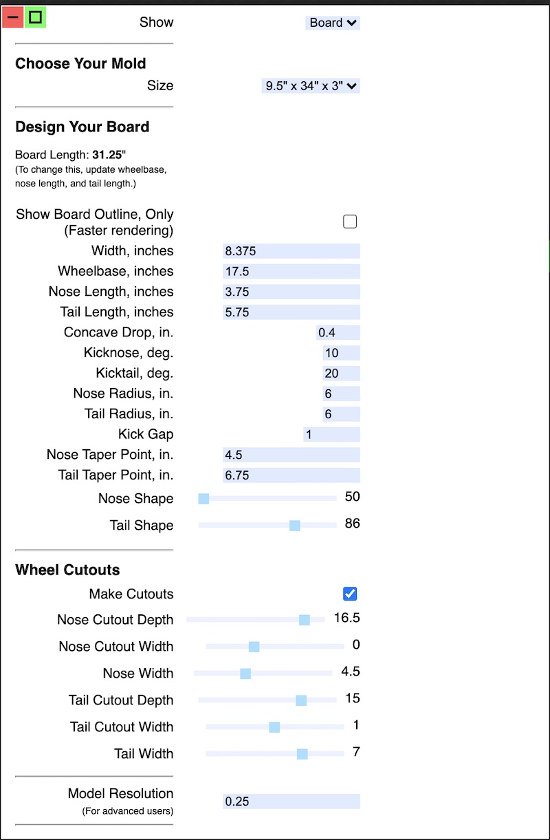
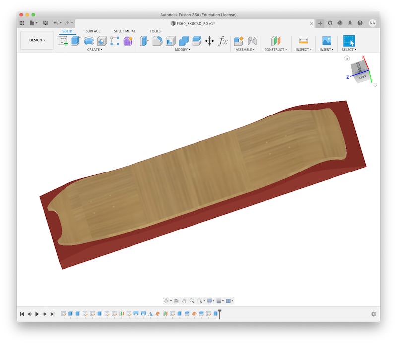
I copied those values in the Fusion 360 file that they provide to generate the same board in Fusion.
Mold Making
To make the mould I had a sheet of 1 inch thick pink insulation foam. I cut to pieces approximately 8x26 inches and used super77 spray adhesive to glue them together to be 2"x8"x26". I will cut this on the ShopBot.
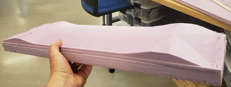
I exported the mold STL and brought that into VCarve to cut it on the ShopBot. Figuring out 3D tool paths in Vcarve was a bit clunky but once I got the model positioned correctly it was fairly straight forward. I did a roughing pass that I now thing was unnecessary. The tool probably could have cut much faster and done it all in a single pass. I couldn’t find a lot of good information on how fast to cut foam. I settled on 100 Inches per Minute. This worked find but I think could have been faster. I did the roughing pass with a 1/4" end mill and I though about using a ball nose end mill to do the finishing pass but the cut time for the ball nose was 2 hours and the flat mill was 15 minutes. So I did the 15 minute version.
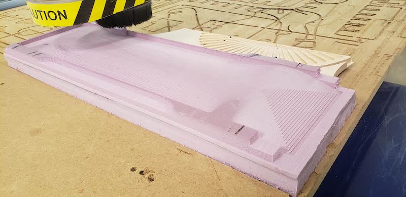
This cut came out fine and I could sand it smooth if needed. Because we’re laminating veneers the surface finish of the mold shouldn’t matter that much.
Layup and Vacuum Bagging
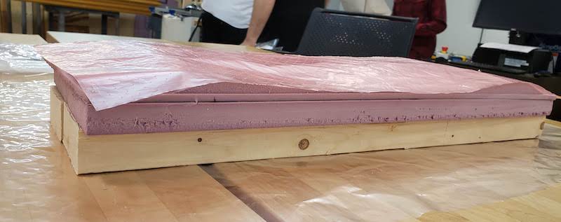
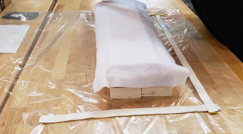
We couldn’t get the right veneers or quite all the right materials to actually do a layup so we just walked through the process. We setup a vacuum bag as if we were going to do the layup but we left out the epoxy. We used some 2x4s to stiffen the foam mold. We then placed that on a large plastic sheet that will become the vacuum bag. On top of the mold we put a sheet of peel ply so we can remove the finished product without ruining the foam mold.
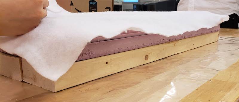
Then we placed the veneers on the peel ply. If we were doing a full layup we would have coated each sheet in epoxy. We placed a perforated sheet of peel ply on top of the veneers. It was topped off with a sheet of felt to absorb the extra epoxy.
We then lined the vacuum bag sheet with double sided putty tape.
Then we folded the plastic over making sure to install a vacuum port in the top. We stuck down the tape to seal the bag all the way around. We hooked up the vacuum pump and helped the vacuum pull the veneers against the mold.
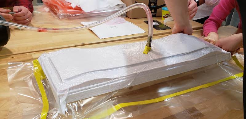
We didn’t have a valve to be able to shut off the vacuum and hold the pressure on the mold. This is why we didn’t do a full layup, but if we had that we could have epoxied the veneers and held this under vacuum for a few hours and had a skateboard.
Design Files:
STL
Fusion File
Aluminum 3 Axis Machining
Design
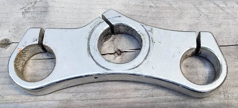
I removed the part I’m replacing from my bike. This is the part as is.
I put the existing part on a flat bed scanner and imported that into Fusion.
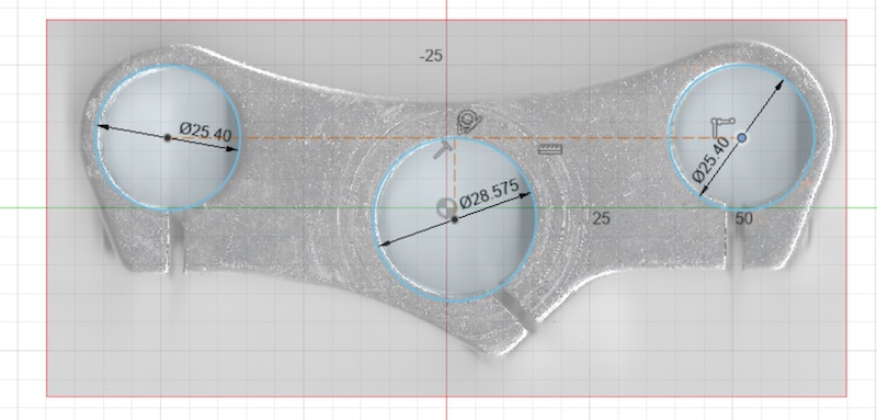
The important change between my part and the original was that the steerer tube is 1" diameter rather than the original 1 1/8". I’m starting with the upper clamp which is a bit simpler. After that works I’ll have to make the lower clamp which will need a shoulder for the steerer tube to sit against to align the headset bearings.
I drew up the part in Fusion.
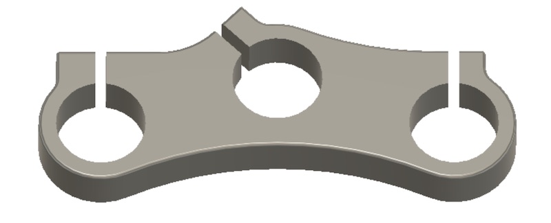
I went back and removed the slots for milling because we don’t’ have a slitting saw. I will cut those manually with a band saw and this will make the other parts stiffer as I machine them.
Milling
Facing
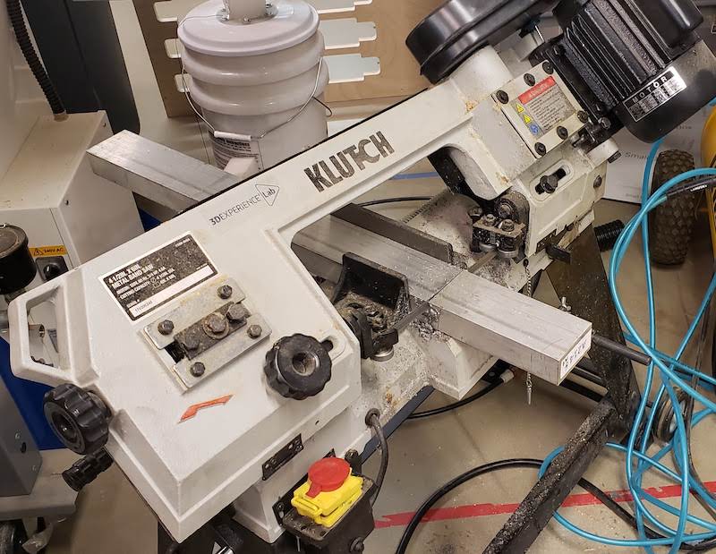
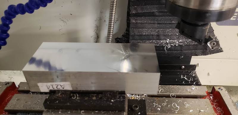
I picked a piece of aluminum stock and cut it to approximately the right size on the horizontal band saw.
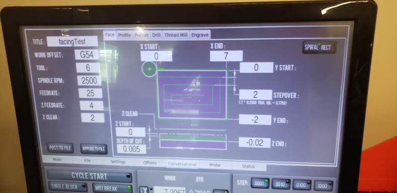
Once that was cut I loaded it into the Tormach PCNC 440. The first task was to use a fly cutter to face off the stock nice and flat. I did some experiments with feeds and speeds. I used NYCCNC’s Superfly test cuts video to get a starting point. I didn’t notice that they’re using a PCNC 1100 which is a twice as powerful machine as our PCNC 440. They suggested 50 FPM feed rate and 0.01" depth of cut as a conservative pass. This cut didn’t work great and stalled the spindle. I cut the depth of cut and feed rate in half and tried again. This worked great and resulted in a beautiful mirror finish.
To do these tests I used Tormach Path Pilot’s “Conversational” menu which allowed for generation of simple gcode operations directly from the control interface.
Testing CAM
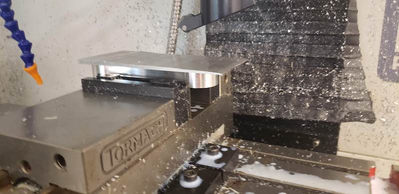
I used Fusion CAM to generate toolpaths to cut my part. I knew my part was a bit large for this tool and it would take a while to cut. I wanted to use the largest tool available which was a 3/8" end mill. To get started with speeds and feeds for this tool I found a very helpful Fusion tool libarary from the Makerspace at NYU. This gave me a good starting point for safe speeds and feeds. I wanted to try to cut the 3 holes and the profile of my part at 1mm deep just to test the machine under light load and do a quick test cut. I setup those two tool paths and moved them over to the mill. The visualizer on Path Pilot is really helpful for double checking everything is going to go as you expect.
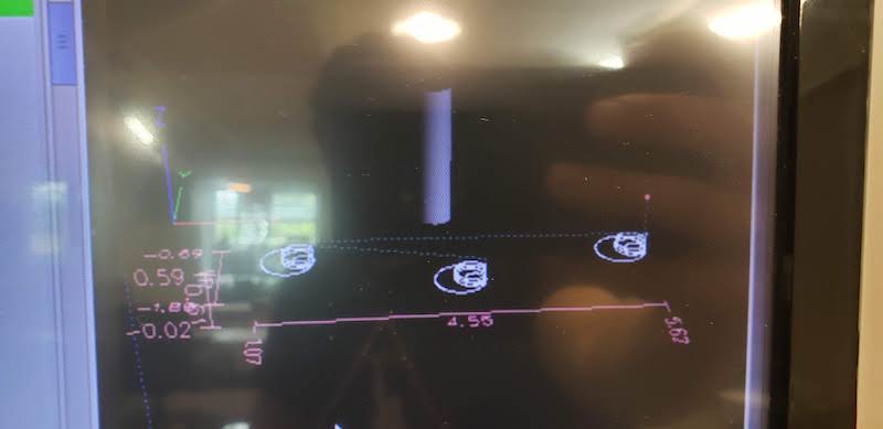
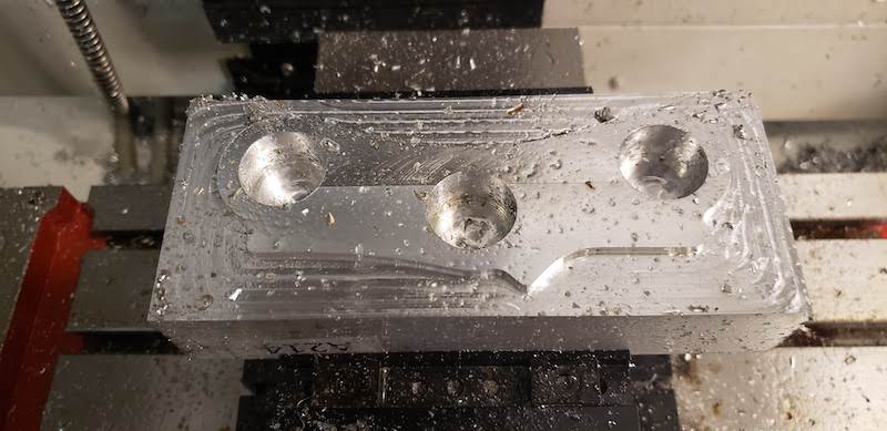
I ran the first operation to pocket the 3 holes. I set them to leave 0.5mm of radial stock behind for a finishing pass. Measuring the result was nearly right on the money as they are 25.6mm in CAD and the end result is 25.18mm.
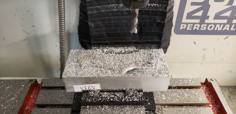
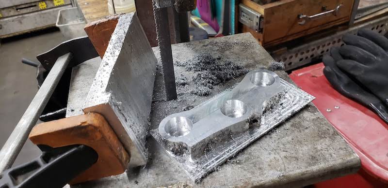
Next I ran the profile tool path. The results hid behind the chips.
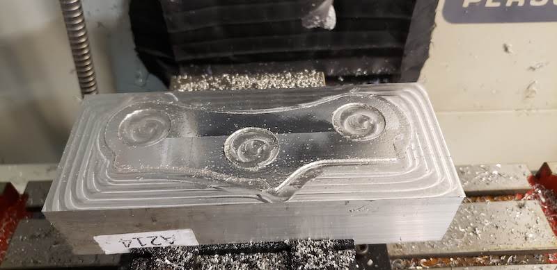
When I brushed it off it looked great.
Cut twice Measure Once
I wanted to check this against the existing part to make sure the outer holes would line up with the existing fork spacing. A misalignment of less than 1mm would have been ok but they were off by about 5mm. I guess something went wrong scaling the scan into fusion. This part doesn’t really have good straight edges or corners to use as reference points but I’m surprised it was that far off. I measured the relevant distance between the outer holes and added that dimension into fusion. I also took this opportunity to clean up the outline a bit and standardize the dimensions fo the tabs where there will be bolts holding the slots closed.
Start Again
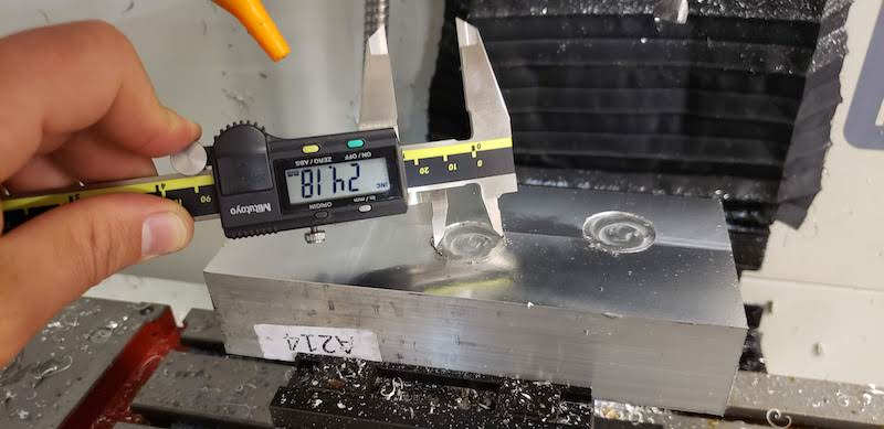
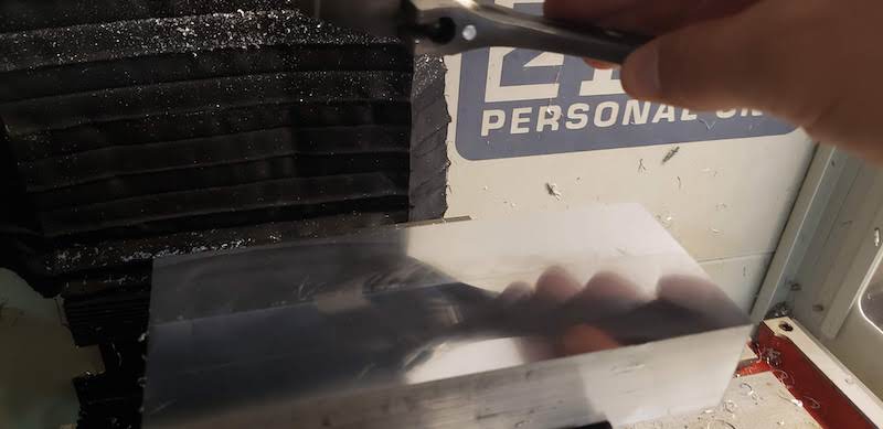
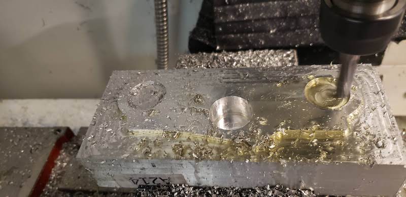
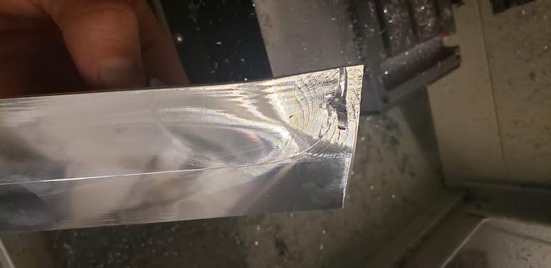
I setup the Superfly again and faced off my previous cuts down to a mirror finish again. You can see the reflection of a wrench in my hand in the surface of the part.
Next I wanted to increase the depth of cut to machine the parts faster. The NYU page I referenced above suggested DOC of up to 50% of the width of the tool. I wanted to creep up slowly because I didn’t want to break a tool as we don’t have many spares. I used Path Pilots gcode generator to do a test cut at 0.1" DOC and 0.01" WOC and that worked just fine.
Using those settings cutting my whole part said it would take about 2 hours of cutting time. I decided that I could keep doing test to get that time down but it would ultimately take the same amount of time so I ran with that.
I did a single pass of the part at those settings to make sure everything was good and it worked fine.
I should also mention at this point that the machine has a coolant system that should be constantly cooling the part and the tool. We had gotten new coolant as it had been sitting for a while but when we tested it out the pump was so covered in corrosion that it didn’t work. So I was being extra conservative with my feeds and speeds. I also had to manually blow away chips and add oil to the stock to keep things cool.
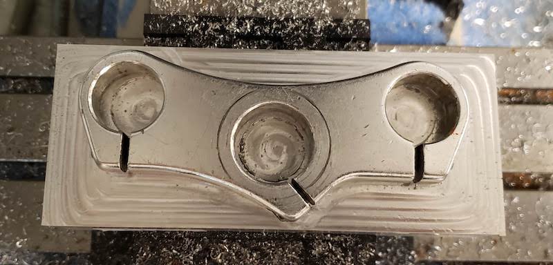
The Long Cut
At this point I was in for the long haul. It was a 40 minute operation to cut the 3 pockets and another 1 hour and 20 minutes to cut the profile. I had to blow away chips and add oil the whole time. This certainly kept me on my toes for the length of the operation. The final result was beautiful.
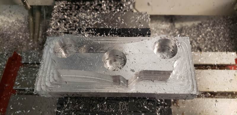
I did a finishing pass on both the pockets and profile with the full 16mm depth of cut taking off the last 0.5mm of stock. The surface finish looked about the same before and after these cuts, further confirming that my speeds and feeds were very conservative. I was also surprised that after each operation the block of aluminum was slightly warm to the touch but the end mill was completely cool.
Finishing with Manual Operations
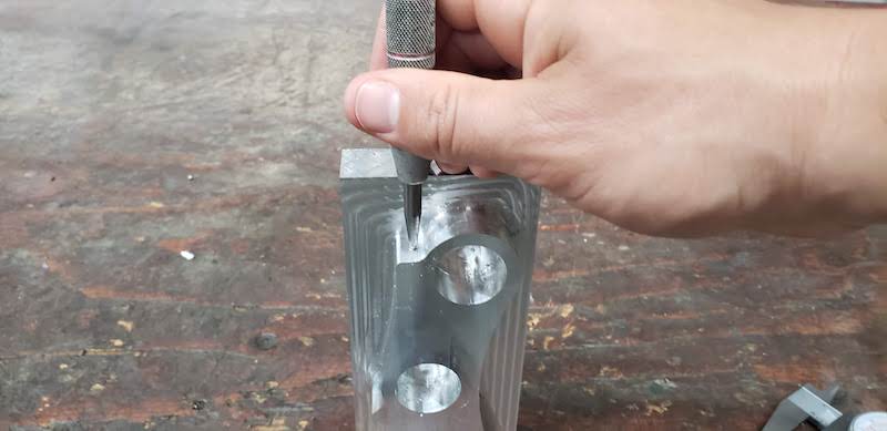
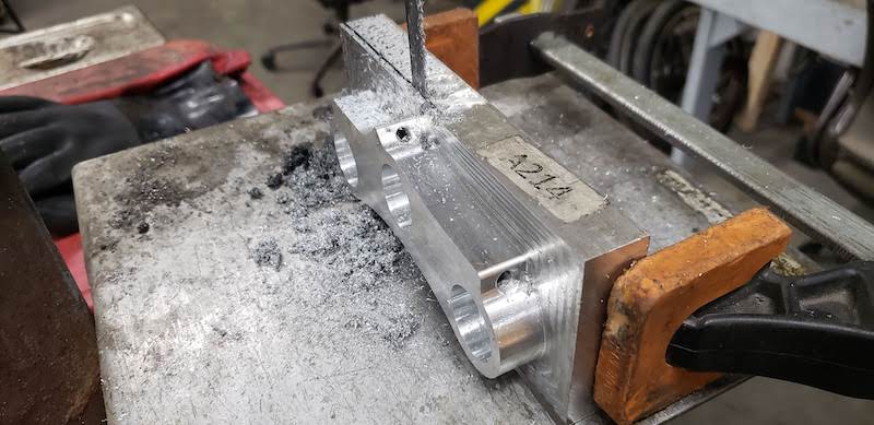
Sadly we don’t have a fourth axis for this machine and I don’t trust myself to realign the part to do the drilling and tapping operations in the CNC machine so I took the part back to the bike shop at Artisan’s Asylum and drilled and tapped the 3 holes for the clamps. I laid out the rough centers with calipers and center punched where the whole should go.
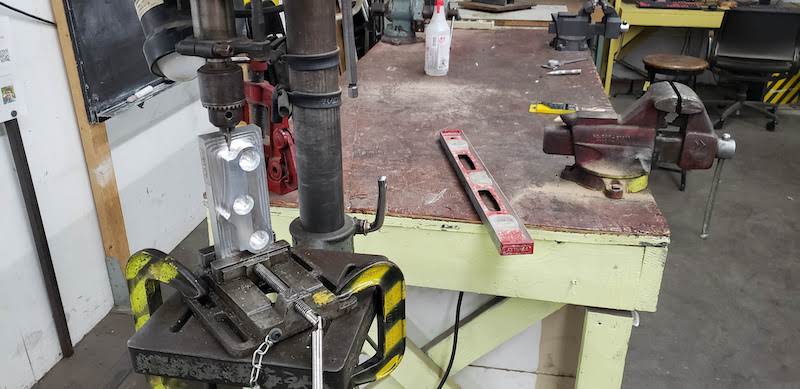
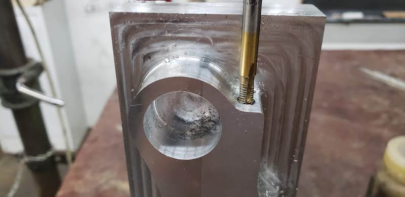
Then I setup the drill press vice and used a level to make sure the vertical face was close enough to vertical. I didn’t have the right drills for an M5 tap so I used a 5/32" drill which is just undersized for the 4.2mm recommended tap drill. This worked well enough for tapping by hand in aluminum.
Next I had to removed the part from the large hunk of stock that was left over. This would have taken forever to use the facing tool to cut 0.005" at a time so I used a vertical band saw to do most of the work.
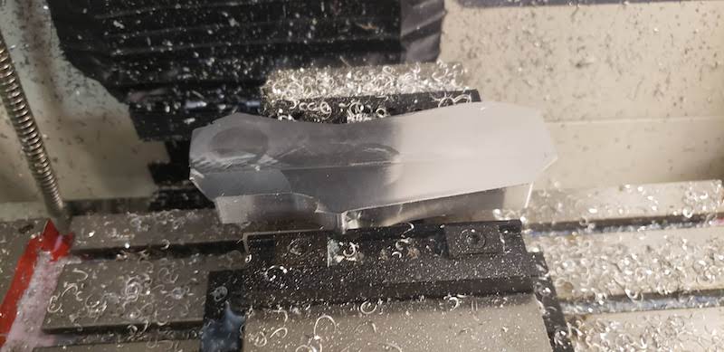
Then I put what was left back in the mill to face it off. Ideally I should have made a fixture or soft jaw to hold the part or at least used shorter parallels to get more of the part in the vice jaws.
This worked for a while. Again I used the Path Pilot gcode generator to run the facing operation. Once the remaining stock got very thin it started to vibrate and eventually the tool grabbed it and bent it stalling the tool.
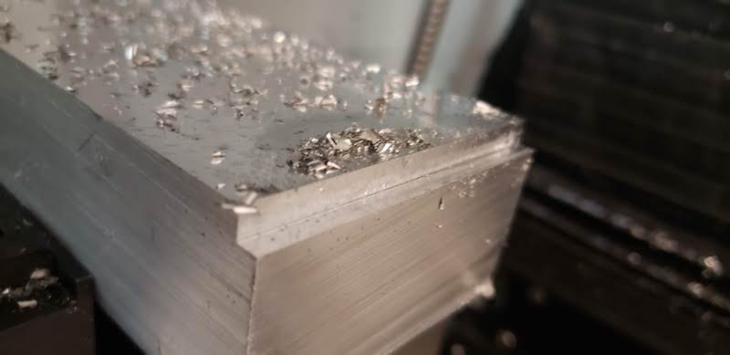
Spencer suggested that I cut most of the thin material off with a hacksaw by hand and then finish the faceing operation.
This worked fine. The last few thin layers of aluminum made some fantastic sci-fy noises as they were peeled away, but it came out great. I wanted cleaned up the edges with a deburring tool and the last thing left to do is cut the slits and test fit it back on my bike.
I went back to Artisan’s Asylum to finish the parts on the vertical band saw. I marked the depth of the pass through holes and the width of cut with calipers and started cutting.
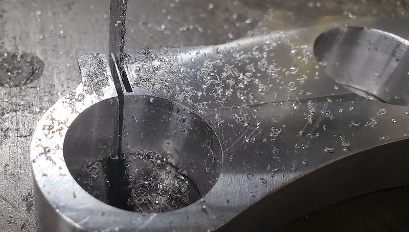
I made two cuts for each slot to make it about 1/8" wide. This measurment wasn’t important as long as the bolt could clamp down enough to reduce the radius even slightly. The first cut looked great.
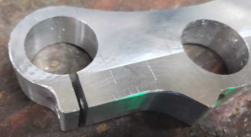
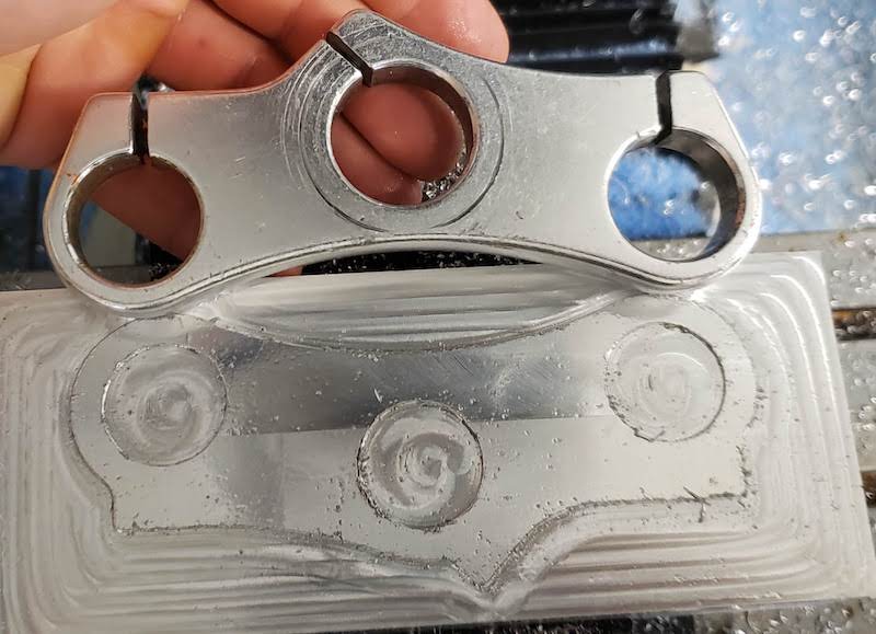
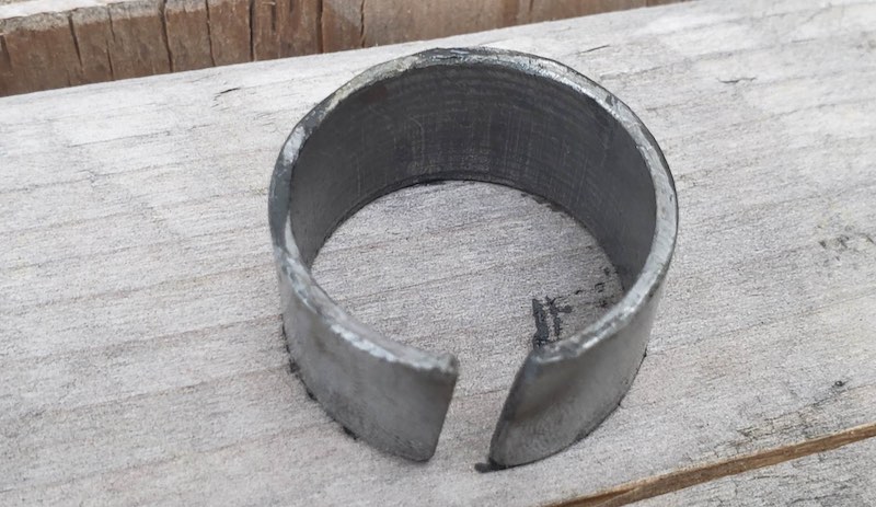
I found a piece of 1 inch steel tubing similar to the fork legs on my bike and it fit perfectly. A snug sliding fit with the bolt loose and tightening the bolt locked it down. I used M5x14 bolts. I wanted them to be slightly longer but I guess I didn’t drill the holes deep enough and I didn’t have a bottoming tap so I couldn’t tap the full depth of the holes.
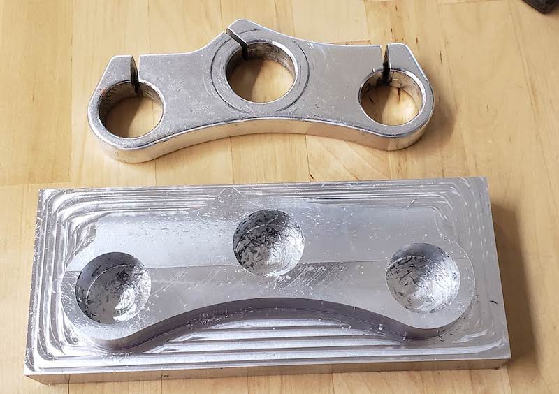
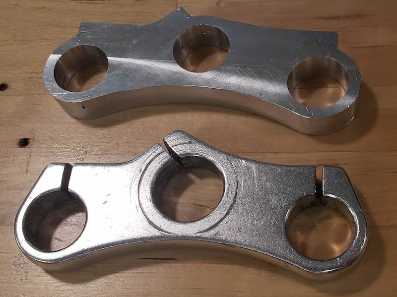
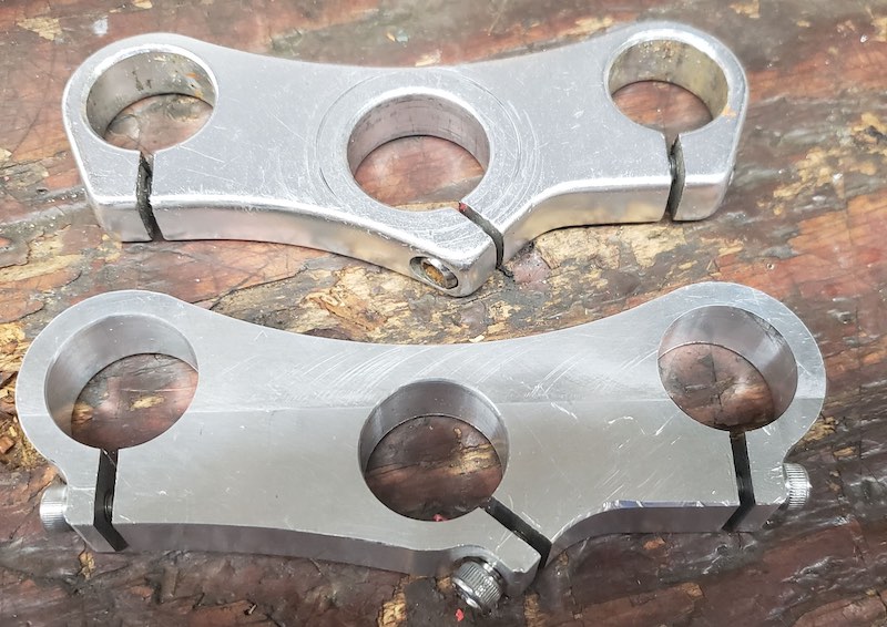
I proceeded to cut the other two slots and used a file to take the sharpe edges off. Original cast part above, new part below. The only major difference is that the center hole is now fit for a 1" steerer tube and not a 1-1/8" steerer.
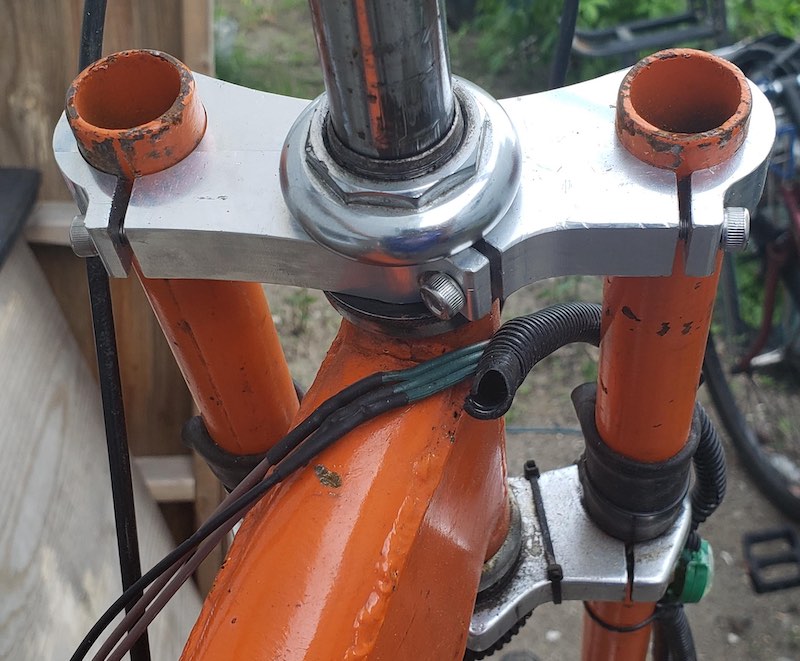
I took it home and installed it on my bike. First I had to remove the spacer that had been making the oversized part fit. It has served well in the over 2000 Light Years of Missions logged here.
I installed it on the bike. The fork legs fit perfect. The center hole is a bit tight over the threaded steerer tube, but I was able to pry the slot open with a screw driver just enough to tap the clamp into place. It looks great.
I still need to make the lower clamp and a new steerer tube but this process gives me confidence to take that on. Then I’ll replace all the bearings and hopefully they’ll last a bit longer, or at least be easier to replace.
I did take it for a quick test ride and it worked fine. no creaking or funny noises or anything.

Design Files: