This week we need to programme the Hello-echo board that we designed in the Electronics Design week.I have experience with the Arduino development also i want to learn more programming stacks so this is the best chance. This week I will program the Echo-board with Arduino , C and also Assembly and I will document my experience here .
An embedded system is a dedicated computer system designed for one or two specific functions. This system is embedded as a part of a complete device system that includes hardware, such as electrical and mechanical components. The embedded system is unlike the general-purpose computer, which is engineered to manage a wide range of processing tasks.
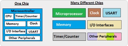
Microprocessor is a central processing unit (CPU) on a single chip. but in Microcontrollers it consists of CPU,Memory Unit (RAM , ROM )and I/O's .But Microcontrollers are extremely slow when comparing Microprocessors
Here we are Focusing on Microcontrollers.
● Harvard architecture ● The Harvard architecture is a computer architecture with physically separate storage and signal pathways for instructions and data.so it can simultaneously use both busses.Von Neumann architecture ● The design of a von Neumann architecture machine is simpler than that of a Harvard architecture machine, which is also a stored-program system but has one dedicated set of address and data buses for reading data from and writing data to memory, and another set of address and data buses for instruction fetching. Harvard architecture has separate data and instruction busses, allowing transfers to be performed simultaneously on both busses. A von Neumann architecture has only one bus which is used for both data transfers and instruction fetches, and therefore data transfers and instruction fetches must be scheduled - they can not be performed at the same time.CISC ● A complex instruction set computer processor has complex instructions that take up multiple clocks for execution. The average clock cycle per instruction (CPI) is in the range of 2 and 15.it's Performance is optimized with more focus on hardware. also It has a memory unit to implement complex instructions.CISC mainly used in Microprocessor.RISC A reduced instruction set computer is a computer which only uses simple commands that can be divided into several instructions which achieve low-level operation within a single CLK cycle, as its name proposes “Reduced Instruction Set”.it's performance is optimized with more focus on software. RISC mainly Used in Microcontroller.
PIC(peripheral interface controller) Initially this was developed for supporting PDP computers to control its peripheral devices, and therefore, named as a peripheral interface device. These microcontrollers are very fast and easy to execute a program compared with other microcontrollers. PIC Microcontroller architecture is based on Harvard architecture. PIC microcontrollers are very popular due to their ease of programming, wide availability, easy to interfacing with other peripherals, low cost, large user base and serial programming capability (reprogramming with flash memory), etc.
AVR is a family of microcontrollers developed by Atmel.These are modified Harvard architecture 8-bit RISC single-chip microcontrollers. AVR was one of the first microcontroller families to use on-chip flash memory for program storage, as opposed to one-time programmable ROM, EPROM, or EEPROM used by other microcontrollers at the time.
Memory is an area where code and instructions are stored.There are normally 3 types of memory present in a microcontroller. These are SRAM, FLASH, and EEPROM memories. ● SRAM is the type of memory where data must be read and written to repeatedly. This is the data that will change the different code being uploaded to the AVR microcontroller circuit. By default, this is the most common and used type of memory. ● Flash memory is the memory that normally stores data that does not change. This is the program memory. It stores the part of the microcontroller program that is fixed and will always stay permanent. This is similar to the BIOS of a general-purpose computer.
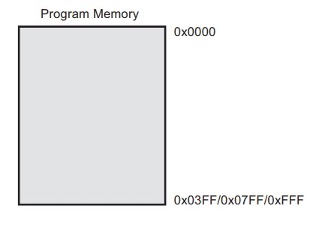
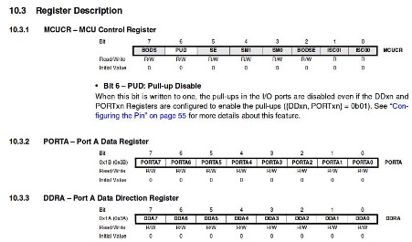
The Flash memory has an endurance of at least 10,000 write/erase cycles. The ATtiny24A/44A/84A Program Counter (PC) is 10/11/12 bits wide, thus addressing the 1024/2048/4096 Program memory locationsRegisters are small memory elements in microcontrollers with 8 bits capacity. Registers can be accessed quickly by the ALU (Arithmetic and Logic Unit) of microcontrollers

This week we need to programme the Hello-echo board that we designed in the Electronics Design week. The Echo board is based on the Microchip ATtiny44 . It's a 8-bit RISC based microcontroller.The Original Design have only the UART Port and I added e a Programmable Button connected to pin PA2 with a Pull-down Resistor and LED connected to PA3 also it's have 20hz External Resonator.
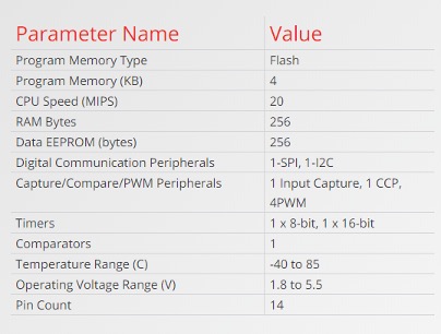
It's a low power AVR® 8-bit microcontroller based on the RISC architecture.It has 12 GPIO pins.

The Atmel ATtiny24/44/84 provides the following features: 2/4/8K bytes of in-system programmable flash, 128/256/512 bytes EEPROM, 128/256/512 bytes SRAM, 12 general purpose I/O lines, 32 general purpose working registers, an 8-bit Timer/Counter with two PWM channels, a 16-bit Timer/Counter with two PWM channels, internal and external interrupts, an 8-channel 10-bit ADC, programmable gain stage (1x, 20x) for 12 differential ADC channel pairs, a programmable watchdog timer with internal oscillator, internal calibrated oscillator, and three software selectable power saving modes The best Guide to know about a microcontroller and Instruction set it's Datasheet.we will get all the information from the Datasheet , only problem is it's not beginner friendly. I started Reading ATtiny44 Datasheet that I got from the Microchip website. For Six -Wire ISP Programming of ATtiny 44 using six pins shown in below ● SCK(Serial Clock): Programming clock, generated by the In-System Programmer (Master) ● MOSI(Master Out - Slave In ): Communication line from In-System Programmer (Master) to target AVR being programmed (Slave ) ● MISO( Master In - Slave Out ): Communication line from target AVR (Slave) to In- System Programmer (Master) ● RST(Reset): To enable In-System Programming, the target AVR Reset must be kept active. To simplify this, the In-System Programmer should control the target AVR Reset ● GND(Ground): Common Ground
● VCC ● Supply voltageGND ● GroundPort B (PB3...PB0) ● Port B is a 4-bit bi-directional I/O port with internal pull-up resistors (selected for each bit). As inputs, Port B pins that are externally pulled low will source current if the pull-up resistors are activated.so we don't need to add a pull-up resistor externally for button's and other purpose.RESET ● Reset input. A low level on this pin for longer than the minimum pulse length will generate a reset, even if the clock is not running.a reset will just reset the program that currently running .Port A (PA7...PA0) Port A is a 8-bit bi-directional I/O port with internal pull-up resistors (selected for each bit). As inputs, Port A pins that are externally pulled low will source current if the pull-up resistors are activated
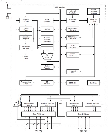
The Block Diagram will explain Architecture of the Microcontroller.The AVR uses a Harvard architecture, with separate memories and buses for program and data. Instructions in the program memory are executed with a single-level pipelining. While one instruction is being executed, the next instruction is pre-fetched from the program memory. The ALU supports arithmetic and logic operations between registers or between a constant and a register. Single-register operations can also be executed in the ALU. After an arithmetic operation, the status register is updated to reflect information about the result of the operation.we will go through all the Stacks when we come to Program the chip.
There are several ways to programme an AVR Microcontroller. Easiest one is using Arduino IDE and there is Microchip Official tool one Atmel Studio also we have a toolchain in GCC.First we are using Arduino IDE.We are using the FabTiny ISP as our Programmer .
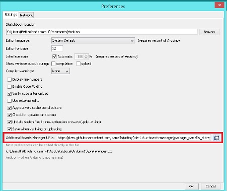
Arduino is an open-source electronics platform based on easy-to-use hardware and software.you can tell your board what to do by sending a set of instructions to the microcontroller on the board. To do so you use the Arduino programming language (based on Wiring), and the Arduino Software (IDE), based on Processing.Anyone can use Arduino. The Arduino system is based on the avr-gcc compiler and makes use of the standard AVR libc libraries, which are open-source C libraries, specifically written for Atmel hardware.You can download the Arduino IDE here.now arduino also have Online IDE. By default the arduino software doesn't contain Attiny 44 chip libraries. We need to include the details manually. In windows we need to install the SPI interface driver , you can download the driver here . ● Install and Open Arduino IDE ● Open preference by clicking File >> preference

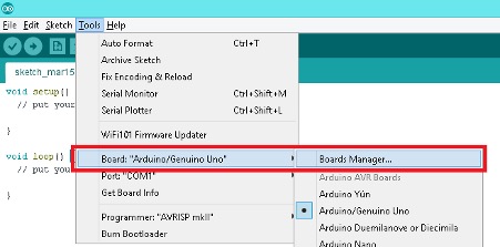
After adding the URL open Board Manager by clicking Tools >> Board >> Board Manager
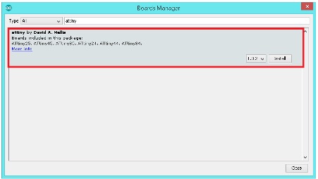
Search for ATtiny44 in the following Window.(Make sure you have Internet connection).and Install the latest version
Now you can select ATtiny44 under the ATtiny Microcontrollers in board Selection

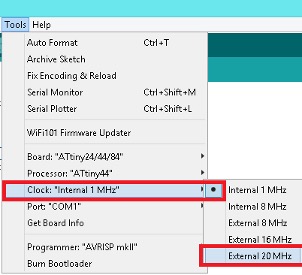
Select appropriate Clock and Programmer.
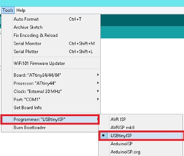
We are using Fab ISP to programme the Hello-Echo board so Select the Programmer as USBtinyISP.
Now all set , first we are going to programme Blink Hello world.
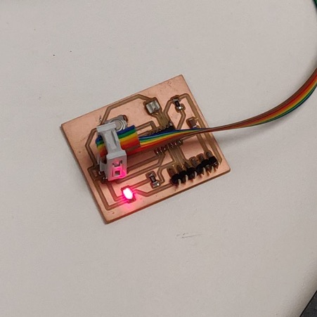
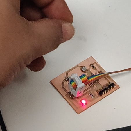
void setup() { pinMode(PA3,OUTPUT); // Set PA3 Pin as OUTPUT } void loop() { digitalWrite(PA3,HIGH); //Set PA3 ON(5v) delay(1000); //Wait 1 sec digitalWrite(PA3,LOW); //Set PA3 OFF(OFF) delay(1000); //Wait 1 sec } Click Upload to flash the Hello-Echo Board
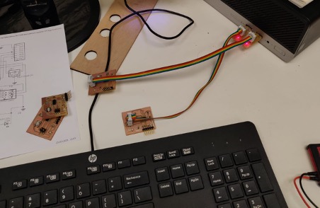
Here I connected Hello board with PC through FTDI cable and also connected with FABISP with ISP header PIN, FABISP directly connects with USB with PC.
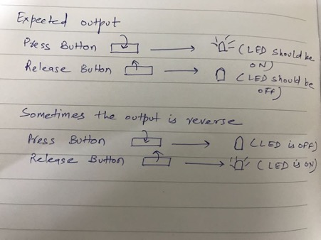
But initially the LED is not blinking but after making some changes in the program then the LED starts to blink. The below images show the output.


After discussing with my instructor I got to know about switch bouncing

I have gone through a couple of registers.DDRA is a data direction register. If any bit is high in this register it means there is an input at that PIN and if low than it is used as output. PORTA data register: If any bit is set then that pin is high otherwise it is low.