As I don't really know this machine I did a bit of research on the basics so I will start by answering two questions: What is a CNC cutter? How does it work?
A CNC, Computer Numerically Controlled, machine is a machine that uses a cutting tool that by rotating at a very high-speed removes material from a part. Apart from being bigger than the Laser Cutter that I used in the 3rd week, i.e. you can cut big things, a main difference between these two machines is that you are able to cut the material with different depths.
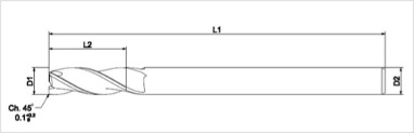
The machine reads a pre‐ programmed computer file telling it where and how to cut. A cutting bit is rotated at a very high RPM by a spindle motor, which can move the bit up and down. This mechanism is moved left, right, front, and back by a cross arm. The machine is therefore known as a three‐axis router because it can move on the XY & Z axis. The machine can do two dimensional cutouts and etching, as well as three‐dimensional relief work. The machine reads a pre‐ programmed computer file telling it where and how to cut. A cutting bit is rotated at a very high RPM by a spindle motor, which can move the bit up and down. This mechanism is moved left, right, front, and back by a cross arm. The machine is therefore known as a three‐axis router because it can move on the XY & Z axis. The machine can do two dimensional cutouts and etching, as well as three‐dimensional relief work. Parts of the tool: ● L1: total length of the tool. ● L2: Cutting length of the tool, we usually choose one that's similar to the thickness of the material. ● D1: width of the cutting section. ● D2: with the tool. Sometimes is not the same as the width of the cutting section.
- Up-cut: they extract the wood chips to the top, they do smoother works in the lower layers. - Down-cut: opposite, they have a better finish in the top layers. - Mixed: they combine both techniques, they are more smooth in the middle. - You can also classify them by the number of cutting edges (1-8). I will use ones with 1 or 2. High ones are for metals.
You can cut MDF, plywood, solid wood, foam,plastics and soft metals(like aluminium) As for learning we recommend to use plywood and foam The thickness of the material should always be measured using a vernier caliper. Do not think that the material will have exactly the thickness that is specified.It never does Always try your joinery first and tolerances first before continuing your design.
● Always remain with the machine while it is running, and be ready to hit the spacebar to pause the file, or the stop button to stop the machine in case of an emergency. ● Always wear eye protection while the machine is running, and have long hair tied back. ● When changing the endmill,Disengage the spindle. ● Use the dust guard. ● No gloves ● AIR CUT to test your design first. ● Caution: Keep collets clean, a piece of debris or dust between the collet and bit can cause the bit to spin elliptically, harming the bit, part or even operator. Your normal glasses are not safety glasses.
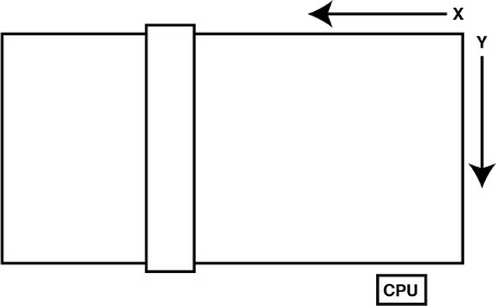
Most of you will use a large Shobpotto mill.(like the Modela) Most of you will have a ShopBot PRSstandard96 The size of the bed of that ShopBot is 4 x 8 feet (or 48 x 96 inches)(2440x1220mm). 1220mm of travel on the X axis 2440mm travel feet on the y-axis 152mm Z-axis travel (with one-inch cutter placed) Collet size ER25 for cutters In our lab we have Shopbot CNC
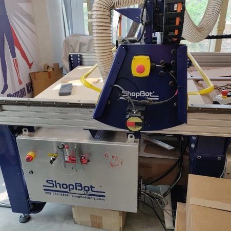

Control Box
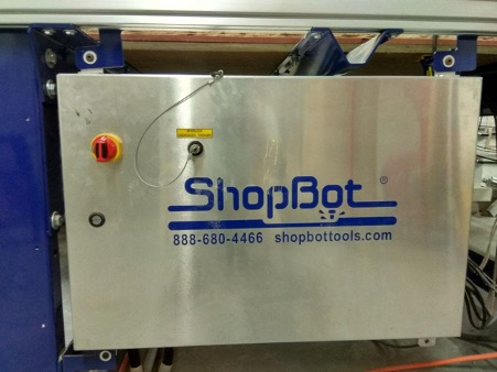
Power Distribution Box
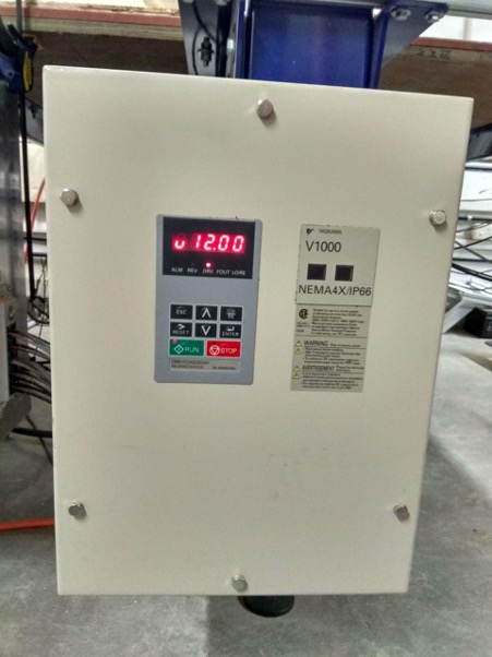
Vaccum Systems
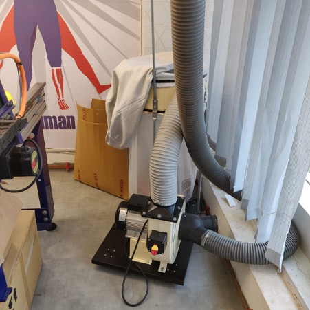
ShopBoat has a Powerful Vacuum Clear to suck all dust that comes when we cut something , it's very helpful.
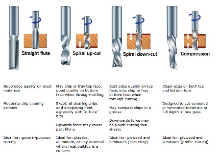
Bit material:Router bits used in Shopbot are made from a variety of materials such as solid carbide, carbide-tipped steel, and high-speed steel. Flute type : There are four basic flute types: Straight, spiral up-cut, spiral down-cut, and compression
Drill bit Vs End mills :A drill bit need to cut straight into the material hence will have teeth at tip. But an End mill needs to cut from the sides also, that means it needs to have a cutting edge spiraling all the way up to the flute.
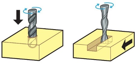
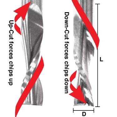
In an Upcut type end mill the teeth on the flute will point upwards. This means that the end mill is cutting and drawing out the wood through the flute. This is good for cutting deep into the stock. But this leaves a bad surface finish on the top of the surface. A downcut type end mill has teeths that point downward on the flute. This means that the end mill will cut and try to push the material into the stock. This will give good surface finish on the top, but it is not very efficient at removing material.
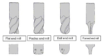
flat end leaves flat surface profile on the stock and are good for removing large volume of material, but steps are formed when used for making curved surfaces. Ball end leaves curved surfaces and forms smooth curved finish while cutting cavities. They are used for finishing cuts.
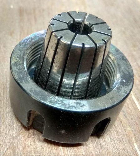

A collet is a subtype of chuck that forms a collar around an object to be held and exerts a strong clamping force on the object when it is tightened. It may be used to hold a workpiece or a tool. We are using ER25 collets, ER collets are slotted (alternately) from both ends and therefore compress onto the cutter along the whole length of the collet when tightened. This not only provides a better grip on the cutter shank but also allows some variation (typically 1mm) in shank sizes that may be used in a single collet. The smaller size collets are best used to hold cutters no more than 0.5mm below the nominal size. Collets are inserted into the covernut.


ESTOP switch is Emergency STOP switches are used for stopping the work during emergencies There are two emergency stop switches will be there, One is an ESTOP box which contains two additional switches one for Starting the spindle and the other for Reset. Ensure these ESTOP switches are in the OFF position position by rotating the RED STOP button on the DONGLE COUNTER CLOCKWISE
Safety is very important while working with the big machines like Shopbot CNC.

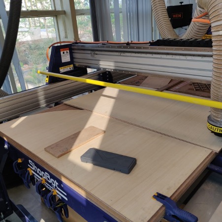
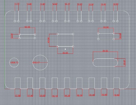
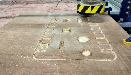
This week We need a test runout, alignment, speeds, feeds, and toolpaths for our machine as part of our assignment. Deigned a test design to learn about the machine tolerances .


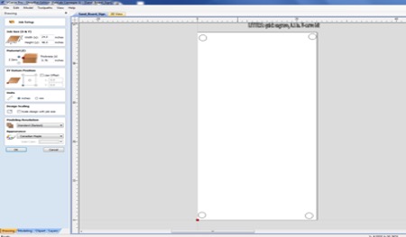
I designed my sign in VCarve. The first thing I did was measure my piece of scrap wood that I was using, and I set up my material to that size. Changing the material settings is very easy in VCarve, and whenever you start a new file, it pops up automatically. After I set up the thickness of the material and set the Z starting point on the TOP of the material, I drew screw hold downs using the circle tool. I will use these holes as a guide to where I can safely place my screws once I put the material down on the ShopBot bed.
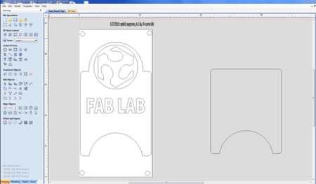
Once my material was all setup in the software, I imported the fab logo as a .jpeg and then I converted it to a bitmap then traced it (similar to the process in CorelDraw) so that I could just use the outlines.


Once I had the logo the way I wanted it, I drew the shape of the sign itself, combining the circle and the rectangle shapes using the weld tool. The one frustrating thing I found in using this software was that it is difficult to measure things precisely.
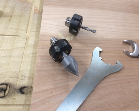
Next, I had to switch the bit on the ShopBot. We had a 1/4" bit in there, and I switched it out to the angled V-Carve bit which is used for engraving. This took a lot of muscling, and I did drop the bit once into the wood, but it seems to have survived.
Before I actually opened a toolpath, I set up the Shopbot for use. I homed the machine using the X-Y home button, which is in the red position box when you open the ShopBot software. This homes the x and y axis at the very edge of the machine, as it uses the built in stops. I also opened up the "Full version" of ShopBot because I wanted to change the jog speeds of the machine manually, because the gantry moves so slowly. I changed the X/Y speed from 1.00 to 5.00 and the Z speed from 0.05 to 1.00.
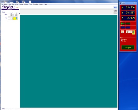
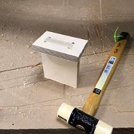
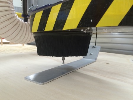
I pulled out the metal piece to home the z axis to the surface of the material. There is a button in the red position window that does this automatically. All I had to do was make sure that the metal piece was underneath the bit and then press enter when it asked.

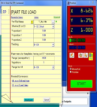
Then I decided to try an "air-cut" to make sure that my cut was positioned correctly. You can do this in the Shopbot software by selecting the 3D-offset selection. This ran the tool above the surface of the material, so I could watch and make sure it would be where I wanted it to be.
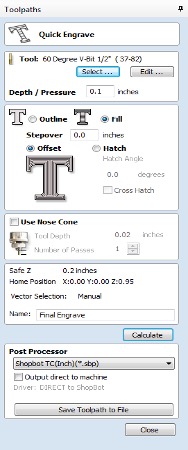
So once I knew that my cut was going to be exactly where I wanted it, I tried my first attempt at engraving the letters. I set up my toolpath in VCarve as a quick engrave toolpath with a fill. I just set the toolpath for one letter so I could see the reults. I saved my toolpath and then opened it in ShopBot. This time I cut it without any 3D offset. It looked terrible.
I think this setting would work better with a flat nose bit where the stepover wouldn't show so much.

I tried changing the depth setting on the engrave toolpath, but the result was much the same. I didn't like being able to see the grooves between passes..

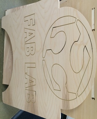
Finally, I tried using the quick engrave toolpath, and I chose "outline."

The result was much better, and I engraved the whole board. Then, I switched bits again (this time being careful not to drop the bit), and I set the profile toolpath to cut out the shapes. Here is the sign after cutting it.