

Week 4's topic was Electronics Production by the way of fabricating a pre-designed PCB module. We were given access to four pre-designed layouts of an "In System Programmer" = which is basically a type of embedded device that has the ability to be programmed 'while installed in a complete system' (as opposed to having a chip that needs to be externally programmed via a "programmer" of sorts).
Week 4's goal was not to "design" the FabISP; rather we had to test how we could "make" or "fabricate" an already-designed FabISP circuit layout, "stuff it" with the requisite semiconductors/electronic components and then proceed to program it (to set it up for use).
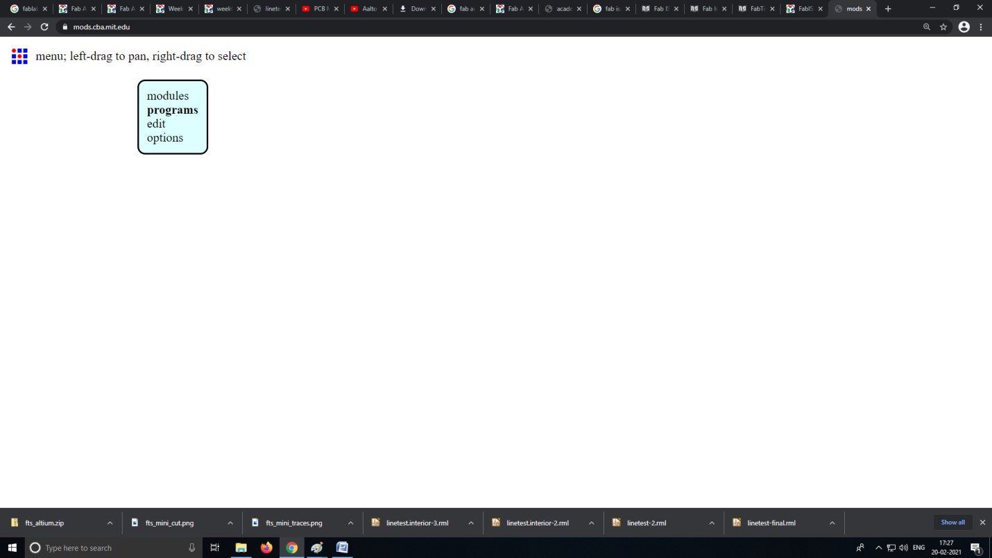
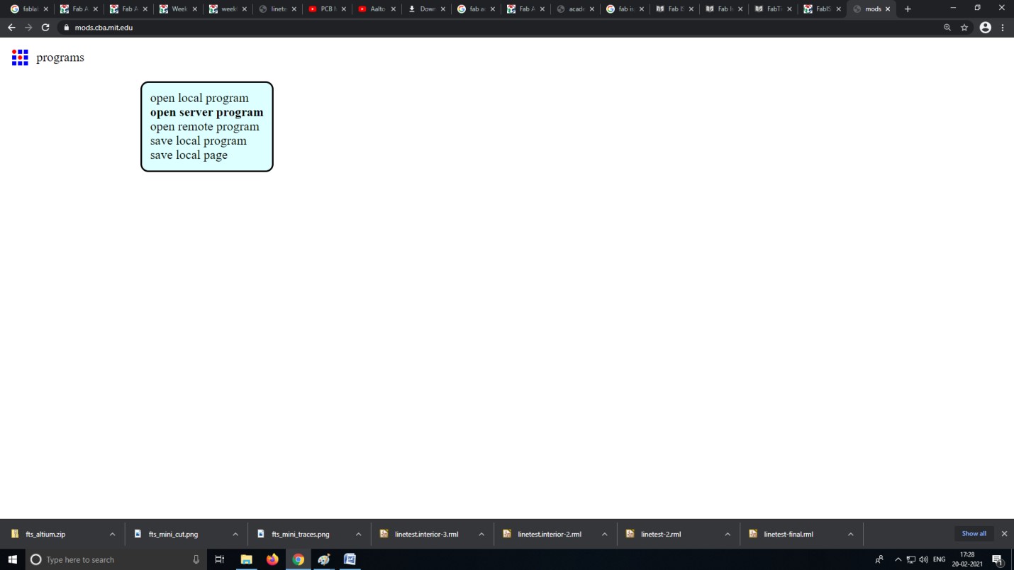
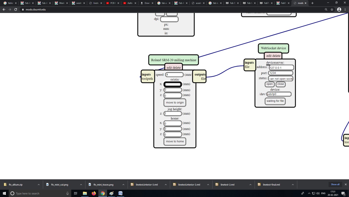
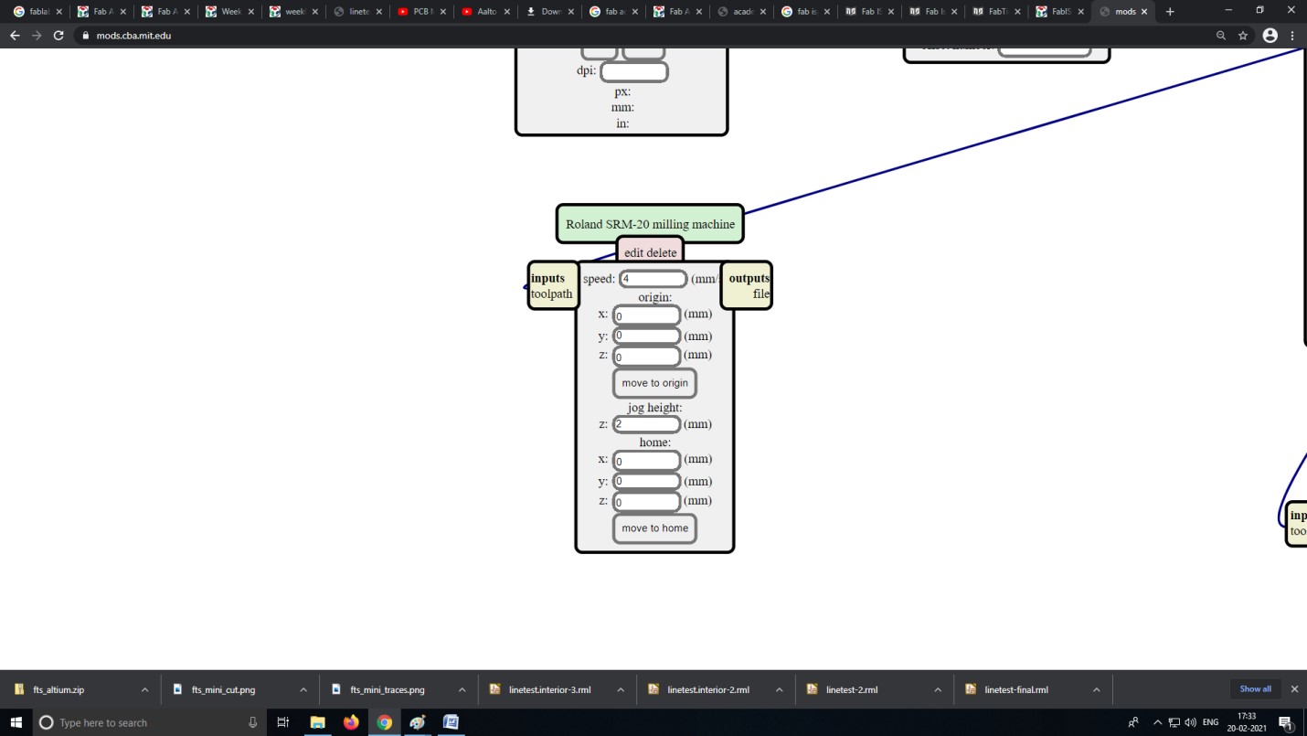
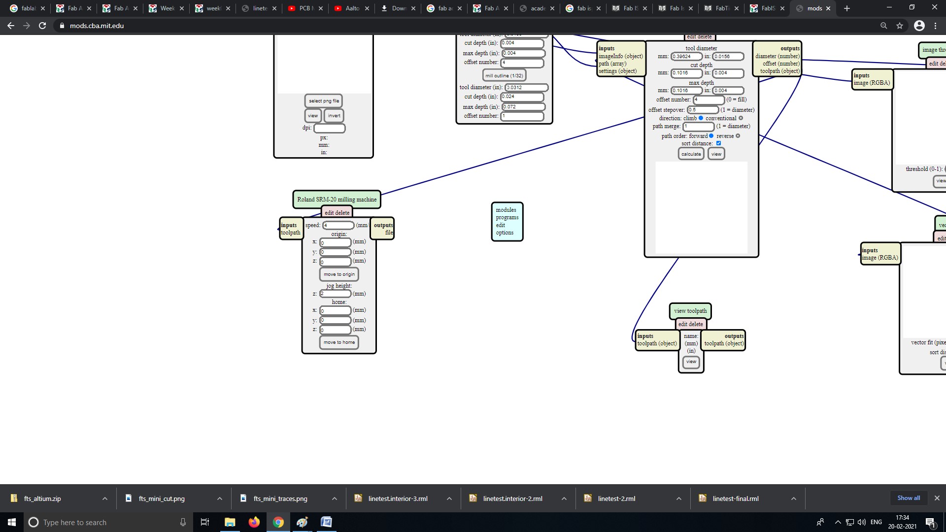
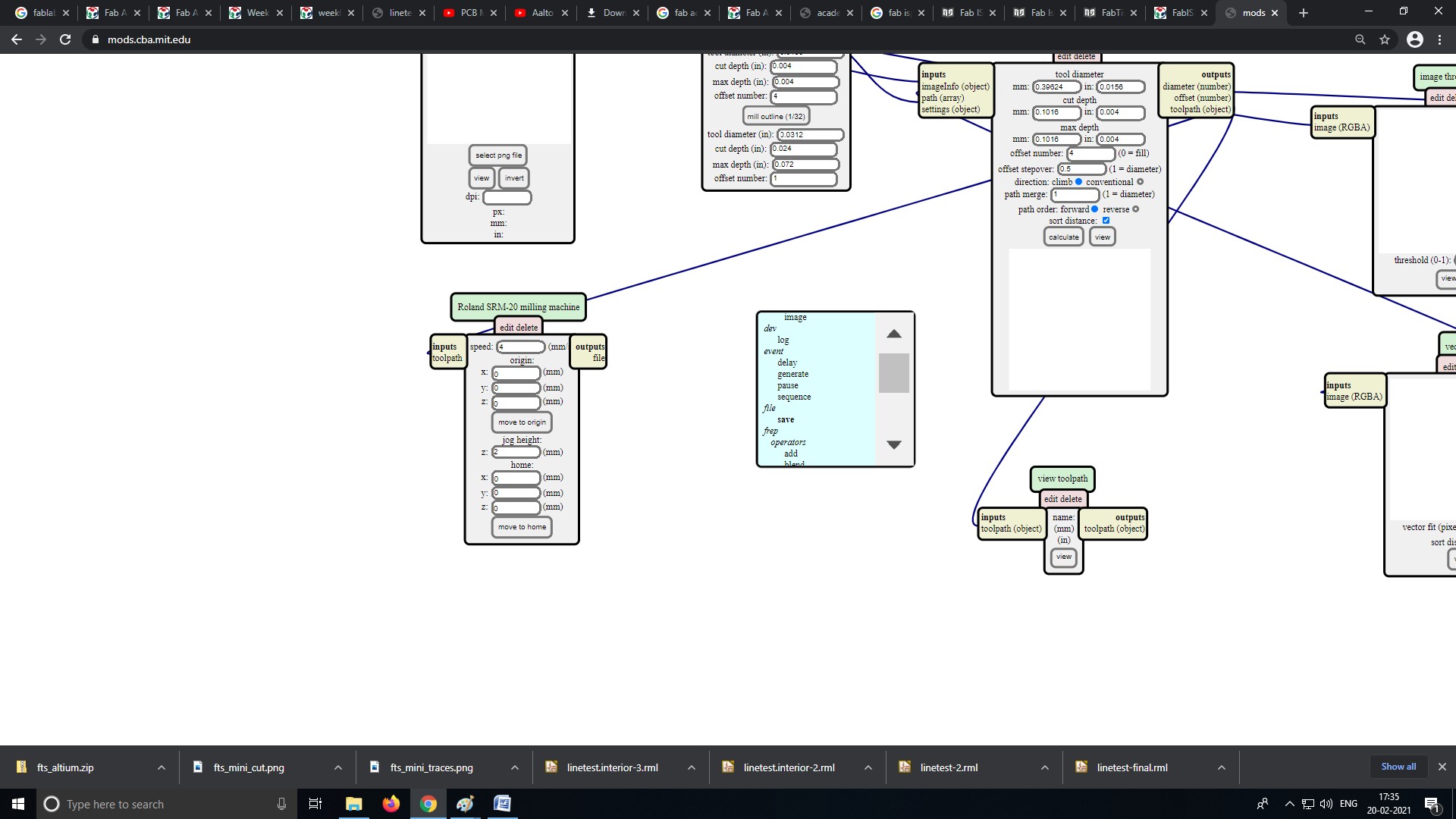
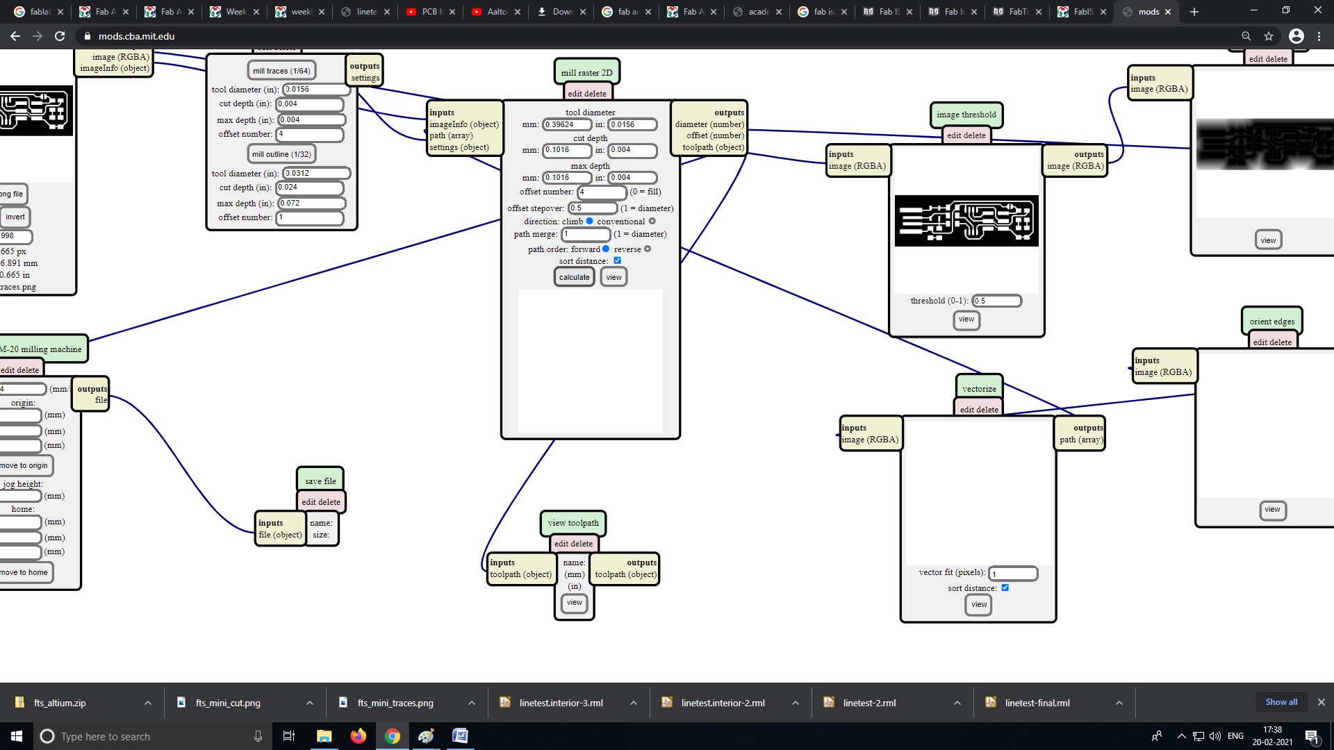
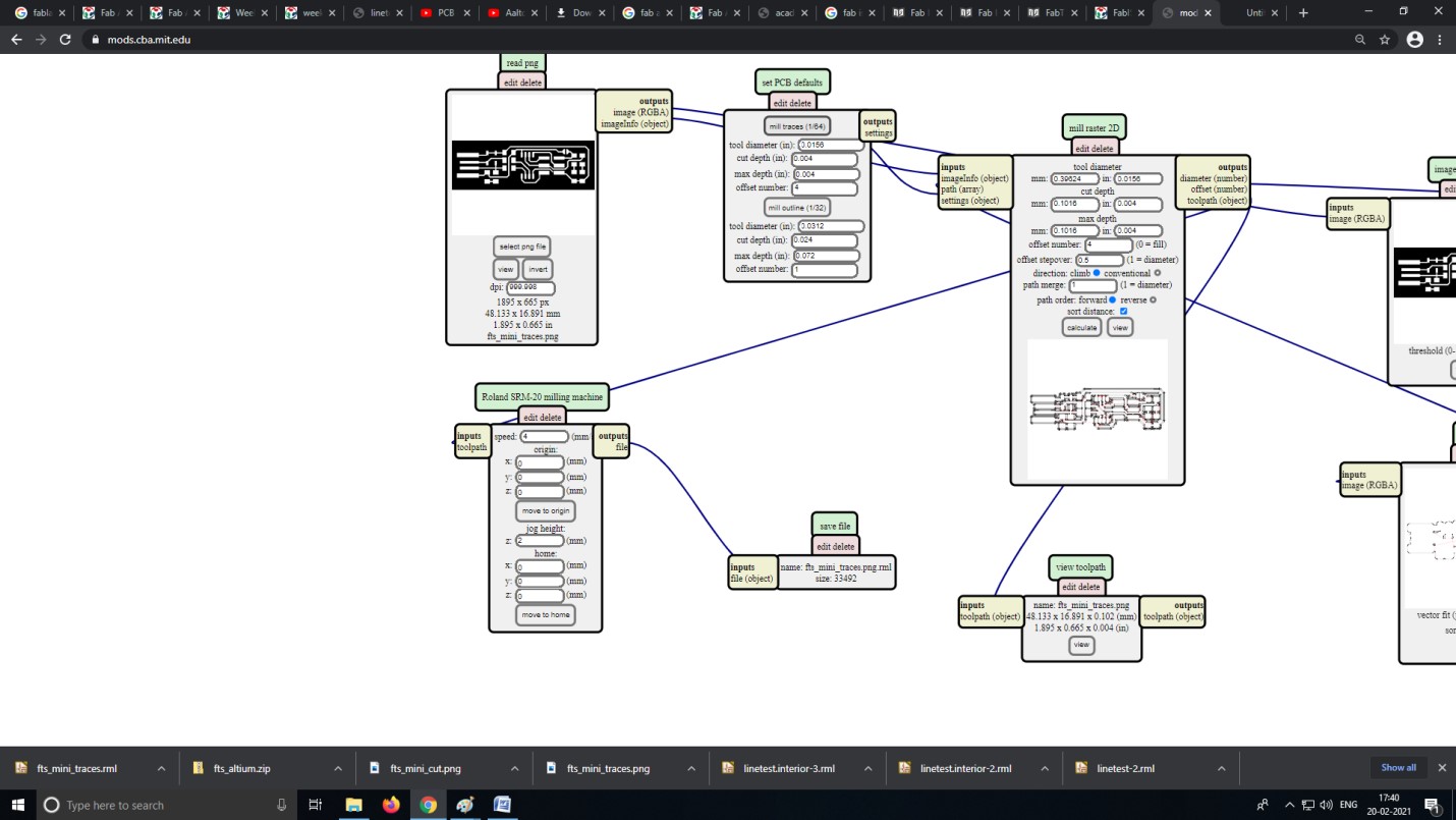
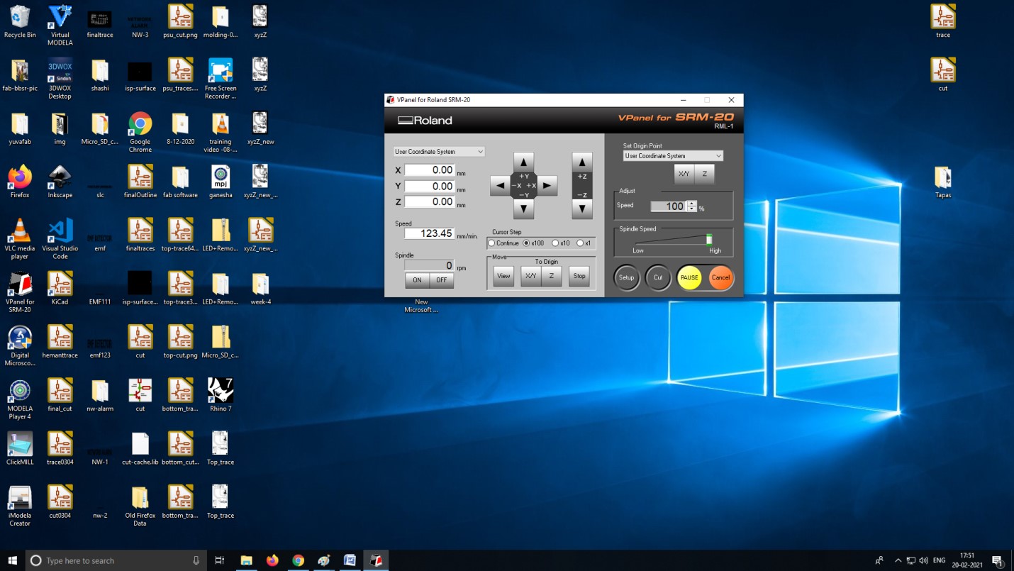
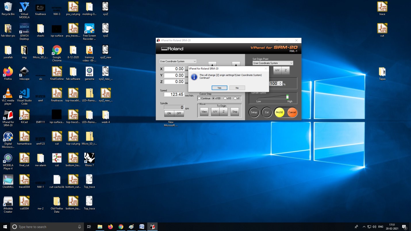
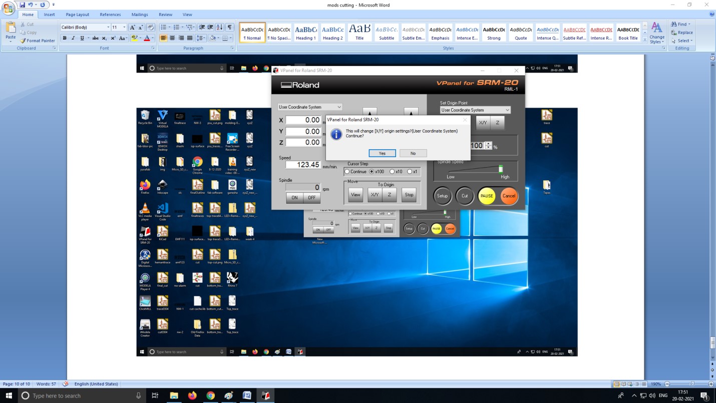
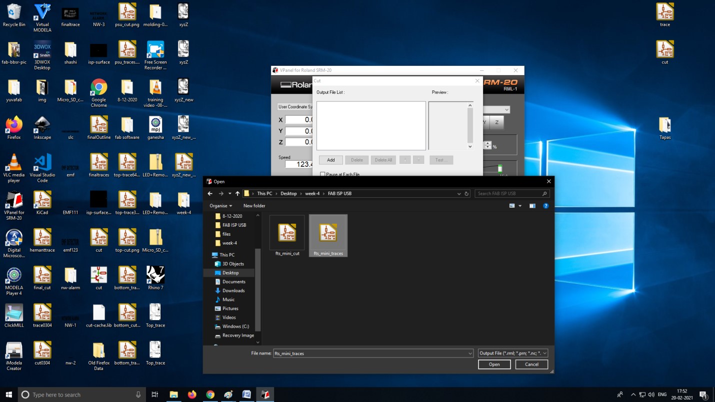
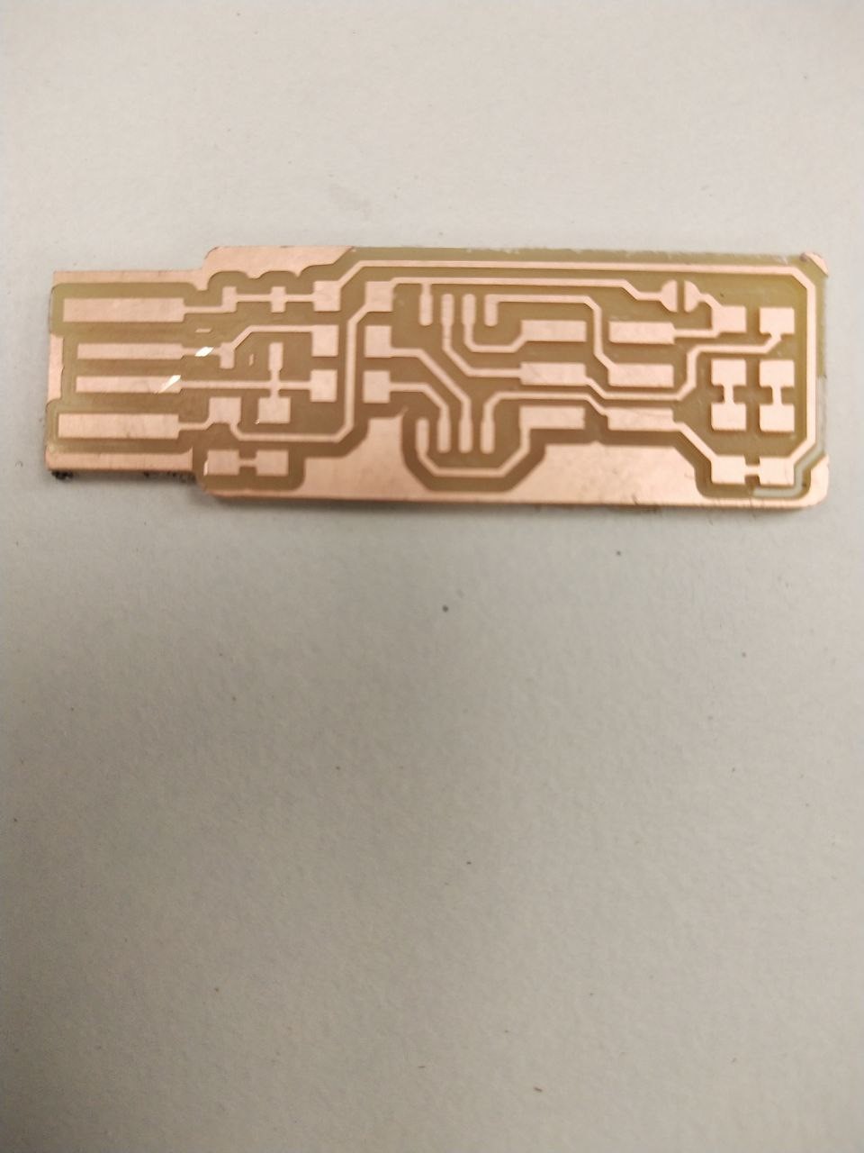
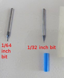
As part of the PCB Fabrication lecture, Neil had discussed several Electronics Production methods such as Etching and Machining among others (Printing, Sewing, Laser Cutting, etc.) which Week 4's assignment asked us to use the Roland Modela MDX-20 to mill our own FabISP PCBs


The equipment used in the soldering is the following
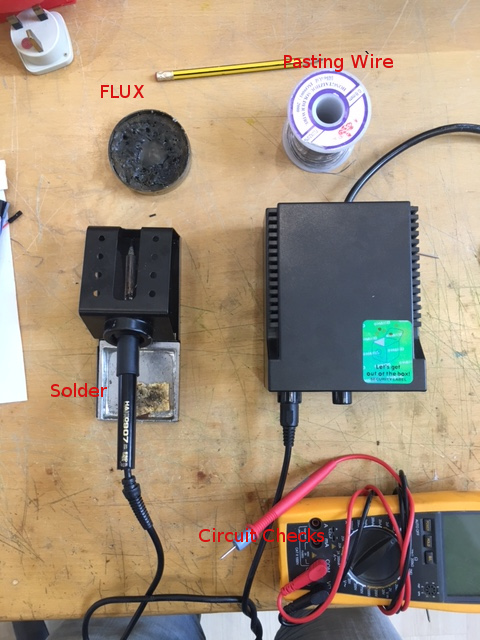
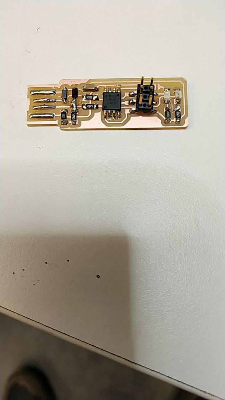
After milling the copper board, I transfered to the soldering station which includes the soldering machines, circuit-shorts check ups and finding all the required components of the circuit. The most difficult part in this process was to assure that the soldering was done properly.

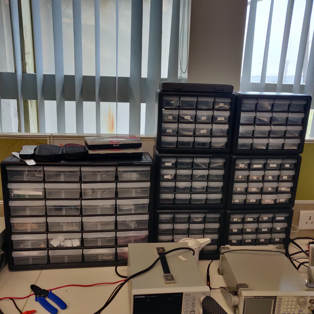
So I really suggest practicing soldering away from your current milled board and get used to it. Below is a picture of all the available components in our lab. so we had to look for each component required for each circuit, list them and then safely place them on a piece of paper in order to assure that the required component was properly selected.
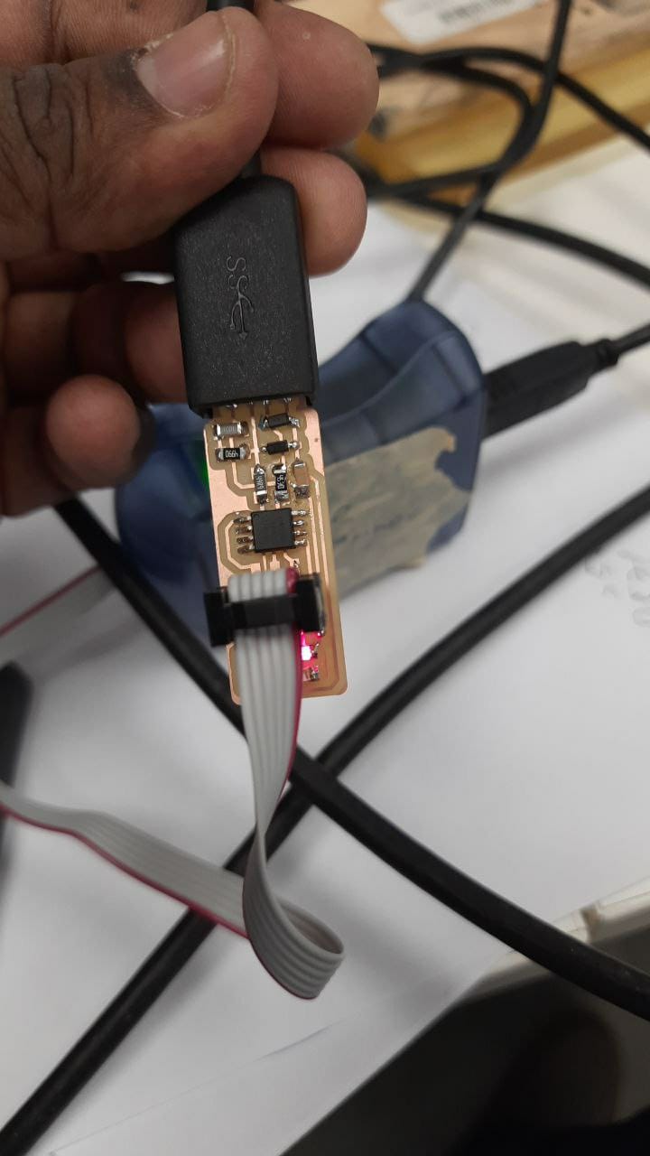
I had to solder each component and check its short-circuits if it beeps or not. Then I had to remove and connect some of the components as I kept failing in connecting it. i repeated all the soldering steps for each component to clear it from any short-circuit if any. The pictures below show some of the progress I have made in finalizing the board. luckily, i succeeded in having a perfectly running circuit and short free as well.
After finalizing the board with all required components, I have started the programing process of the microcontroller in the board by downloading the files from fablab website by downloading the following software Crosspack for AVR. Then I downloaded the FabISP Firmware.. Then I connected the board and started the programming process. Below is the final step captured as a screen shot.
After that, programming the board was also succesfull. The pic above of the final programming. I finally got a working FabISP!!!
Since I was new to soldering in general, I couldn't figure out the problem for the first time. After carefull examination for several times I am able to correct my mistakes and resoldered. It was a good experience with electronics production.